Tertium NFC SCANNER User manual

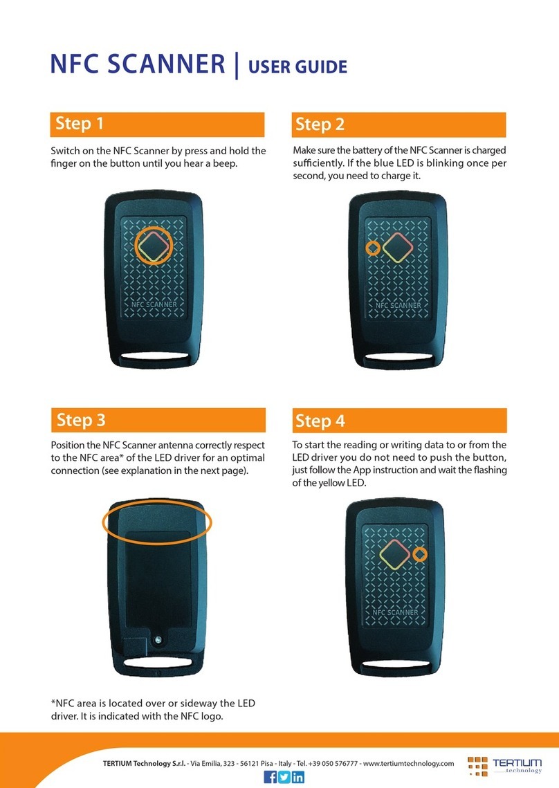
NFC SCANNER

Index
•
Introduction to NFC Scanner [ 4 ]
◦
Contents inside the pack
[ 4 ]
◦
NFC Scanner components
[ 4 ]
◦
Using function key LED and beeper
[ ]
◦
Technical specifications
[ 6 ]
•
Instructions for use [ 7 ]
◦
Installation
[ 7 ]
◦
Connection of NFC Scanner to the computer
[ 7 ]
◦
Disconnection of NFC Scanner
[ 7 ]
◦
Connection of NFC Scanner through Bluetooth
[ 7 ]
◦
Charging the battery
[ 8 ]
◦
Control of the battery charge status
[ 8 ]
◦
Hardware reset
[ 8 ]
◦
Reading distance
[ 9 ]
•Configuration of NFC Scanner [ 9 ]
◦
Bluetooth
®
[ 10 ]
◦
Auto off
[ 11 ]
◦
Set mode
[ 11 ]
◦
Power
[ 16]
◦
Speed
[ 16]
◦
Standard
[ 16]
◦
Baudrate
[ 16]
◦
Sending commands with TT_RFID_Configurator
[ 16 ]
NFC Scanner v.0. – User Manual ver. 0.
January 2017
2

•Option settings [ 17]
◦
Bluetooth
®
authentication
[ 17 ]
◦
Prefix and suffix
[ 17 ]
◦
Add delay sending string via Bluetooth
[ 17 ]
◦
Quick press code
[ 17 ]
◦
Extension flag
[ 17 ]
◦
Option flag
[ 18 ]
◦
RF timeout
[ 18 ]
•
Other information and support
[ 19 ]
NFC Scanner v.0. – User Manual ver. 0.
January 2017
3

Introduction to NFC Scanner
Contents inside the pack
NFC Scanner RFID Reader
USB cable A-type male - micro USB male
Flyer with link to SDK
NFC Scanner components
Figure 1: NFC Scanner components
NFC Scanner v.0. – User Manual ver. 0.
January 2017
4

utton , LED and beeper usage
NFC Scanner v.0. – User Manual ver. 0.
January 2017
5

Table 1: Button , LED and beeper usage
Table refer to the operating mode with standard settings. The button can be eable also to start scanning
Technical specifications
MAN/MACHINE
INTERFACES 1 function key for RFID read activation, poweron/off
Multitone Beeper
2 LED for device operation signaling
INTERNAL DEVICES Frequency: 13.56 MHz
Channel occupancy in accordance with:
•
ETSI EN 302 330-2 V1.6.1, ETSI EN 300 328 V1.9.1
Power: 200 mW
Standard: ISO 15693, ISO 14443-A (only ID reading)
Reading distance: up to 6 cm(*)
Embedded antenna
INTERFACES Micro USB type B
Bluetooth
®
low energy technology
OS COMPATIBILITY Android, iOS, RIM, Windows Mobile/Phone, Windows, OSX, Linux compatible with
Bluetooth
®
low energy technology
PROCESSOR Texas Instruments MSP430 (16 bit RISC a 16MHz)
POWER SUPPLY USB powered: 230mA peak @ 5Vdc (RF active full power,beeper,battery charging),
30mA @ 5Vdc (idle mode,battery charged)
Battery powered: Li-Poly Battery 3.7 Vdc 300mAh, rechargeable via micro USB, battery life
15000 reading, 24 h in idle mode
WORKING
TEMPERATURE -20°C / 60°C
DIMENSIONS Width 4.3 cm – Height 7.7 cm – Depth 1.7 cm
WEIGHT 21 g
PROTECTION DEGREE IP54
(*) depending on the TAG
Table 2: Technical specifications
NFC Scanner v.0. – User Manual ver. 0.
January 2017
6

Instructions for use
Installation
When NFC Scanner is connected to the computer for the first time, if an internet connection is
available, an automatic installation take place. If the internet connection is not available or no suit-
able driver is automatically found download driver and installation guide at the following link:
http://www.ftdichip.com/Drivers/VCP.htm
Connection of NFC Scanner to the computer
Connect NFC Scanner to the computer to recharge the battery, to configure the device through the
TT_RFID_Configurator application, to carry out operation testing through the TT_RFID_PCDemo
application or to send commands to it according to the specific TERTIUM Technology protocol (see
TERTIUM_RFID_Reader_Protocol.pdf ).
Connect NFC Scanner to a USB port.
Once connected, the state of the LEDs and the acoustic signal will indicate the state of the RFID
reader as explained in the paragraph “Charging the battery”.
NOTE: when NFC Scanner is connected to the computer through USB, the Bluetooth
®
interface is
enabled as well. Once NFC Scanner is connected to Bluetooth
®
interface the USB interface will be
disabled. To use USB interface again unplugged NFC Scanner, switch it off if necessary and plug it
again.
Disconnection of NFC Scanner
To disconnect NFC Scanner from the computer, simply disconnect the USB cable. If Bluetooth
®
interface is not connected the reader switches off automatically.
To switch off NFC Scanner when Bluetooth
®
interface is connected, press the button for 2 seconds
after disconnecting the cable.
Connection of NFC Scanner through luetooth
®
NFC Scanner can be connected through Bluetooth
®
low energy to any device such as a computer
or smartphone supplied with this interface.
To connect and use NFC Scanner you need a specific application that can connect to a Bluetooth
Smart device and manage a bi-directional communication.
If NFC Scanner is powered via USB and the Bluetooth connection is active, the user can unplug the
reader without loosing the connection; NFC Scanner will be automatically battery powered.
When connected via Bluetooth
®
the blue LED stops to makes the 3 quick flashes.
NFC Scanner v.0. – User Manual ver. 0.
January 2017
7

Charging the battery
NFC Scanner is equipped with an internal, non-user-replaceable, rechargeable battery. The high
performing Li-Poly battery guarantees up to 1 000 readings.
A discharged battery is completely charged in about 3. hours.
To recharge NFC Scanner, connect it to the computer via USB or a wall adapter power supply. The
reader automatically switches on and the state of the battery charge is signalled by the blue LED
as described in the following paragraph.
Control of the battery charge status
When the NFC Scanner is switched on with the button, the following situations related to the
battery’s charge level may occur:
•an acoustic signal and a fixed blue LED: charged battery (*)
•an acoustic signal and the blue LED blinks each seconds: low battery charge (*)
•no acoustic signal and quick blinking blue LED: battery charge very low. No operation is
possible in this condition; if the reader is not switched off, it will automatically switch off
after 10 sec. It is recommended to charge NFC Scanner up to complete recharge.
If the blue LED starts to blink every seconds during normal use of NFC Scanner, it means that very
little charge is left. The reader will only have few minutes of autonomy.
If you continue to use it, the LED will begin to blink quickly signalling a very low battery charge as
described above.
When NFC Scanner is connected to the computer, the following situations related to the battery
charge level may occur:
•an acoustic signal and a fixed blue LED: charged battery (*)
•an acoustic signal and blinking blue LED: battery charging (*). While charging it's possible
to use NFC Scanner as usual, both connections USB or Bluetooth
®
are available.
(*) 3 quick flashes each 3 seconds means Bluetooth
®
disconnected
In Table 1, you can see the activities of the blue LED and of the acoustic beeper related to the bat-
tery level.
Hardware reset
To reset the device hold the button for 6 seconds (yellow led is switched on during this interval
time) until NFC Scanner makes the power on sound.
Reading distance
NFC Scanner is equipped with an integrated antenna, for the reading of TAG RFID, located above
the button as shown in Figure 1.
The ideal reading distance and conditions for NFC Scanner are as follows.
NOTE: the reading distance varies based on the type of TAG. Also, metal objects and surfaces
located very near NFC Scanner can notably invalidate the reader's performance.
NFC Scanner v.0. – User Manual ver. 0.
January 2017
8

NFC Scanner reader supports the ISO 1 693 standard and ISO 14443A (only ID) and is able to
read TAG RFID to a maximum distance of 6 cm. The optimal conditions of reading are obtained
positioning the TAG inside the field pointed out in Figure 2 (the figure is for example purpose only
and doesn't represent the real antenna radiation pattern).
Figure 2: reading field of NFC Scanner
Configuration of NFC Scanner
NFC Scanner is an RFID reader able to read one or more TAGs and to transmit data via Bluetooth
®
or USB to any device provided with such interfaces.
NFC Scanner is a highly configurable device: it is possible to choose scanning activation mode, the
scanning timeout, the enabling/disabling of the signalling LED and the acoustic beeper, the frame
format, etc.
The configuration can be done through the serial commands, as described in the document
TERTIUM_RFID_Reader_Protocol.pdf
or more simply through the
TT_RFID_Configurator
application supplied in the SDK.
To configure NFC Scanner using
TT_RFID_Configurator,
connect NFC Scanner to the computer with
the USB cable and execute the application; in the section “Device selection”, select the BlueBerry
HF device to configure and the COM to which it is connected. Click on the “Connect to device”
button. If the connection is successful, the LED next to the Com becomes green and the state of
the device and the firmware version will be indicated below (e.g. “Status: Connected v9.2”).
Click on the button “Read config” to read the current configuration of NFC Scanner.
The
TT_RFID_Configurator
main window with the default configuration of NFC Scanner is shown
in Fig. 3.
NFC Scanner v.0. – User Manual ver. 0.
January 2017
9

Figure 3: TT_RFID_Configurator
To save the changes click on the button “Write config” .
luetooth
®
Bluetooth
®
low energy interface doesn't implements SPP or HID profiles.
Bluetooth
®
low energy name and pincode are available in the label on the bottom side of the NFC
Scanner. For example:
BBN00046-668741
where:
BBN00046 is the Bluetooth
®
low energy name
668741 is the pincode
These, together with other parameters, are available sending specific commands via USB or
remotely.
NFC Scanner v.0. – User Manual ver. 0.
January 2017
10

Auto off
It is the time of automatic switching off of NFC Scanner. The auto-switching off mechanism is not
active when NFC Scanner is connected to the computer with the USB cable. Autooff timer is reset
every time the reader found a tag while scanning or when it reaceive a command from the host.
Set mode
Figure : TT_RFID_Configurator - scanning mode parameters
Operation modes
“Normal mode”
In this mode NFC Scanner operates only as a slave peripheral therefore it is only possible to send
commands through the serial USB or Bluetooth
®
interface.
To carry out a scanning, it is necessary to send an INVENTORY command. The yellow LED will turn
on fixed during the scanning time (the
Ts
scanning timeout that can be configured by the user is
200ms by default).
After scanning the behaviour of the reader will depend on the ID_format set as follow.
ID_format = 128
If the reader finds a tag it sends a list of commands. If it gets a successful response and the
Bluetooth
®
connection is active the reader makes a successful sound (3 different beeps) and sends
data. If the list of commands fails or it succseeds but Bluetooth
®
is disconnected the reader makes
the error sounds (2 identical beeps)
ID_format ≠ 128
If a TAG is identified, the reader makes an acoustic beep and the yellow LED will blink 2 times.
Immediately after, NFC Scanner sends the ID of the identified TAG on the active connection, USB
or Bluetooth
®
, and it makes 3 louder acoustic beeps while the yellow LED will blink 3 times.
The “Normal mode”, therefore the possibility to send commands to NFC Scanner, will still remain
active when the reader is configured in the other modes.
aut int
parameter not used for this operation mode, please leave
aut int
= 0.
“Scan on input”
In this mode, the scanning is started pressing the button. The yellow LED will remain fixed on
during the scanning time (the
Ts
scanning timeout that can be configured by the user is 200ms by
default).
After scanning the behaviour of the reader will depend on the ID_format set as follow.
ID_format = 128
If the reader finds a tag it sends a list of commands. If it gets a successful response and the
Bluetooth
®
connection is active the reader makes a successful sound (3 different beeps) and sends
NFC Scanner v.0. – User Manual ver. 0.
January 2017
11

data. If the list of commands fails or it succseeds but Bluetooth
®
is disconnected the reader makes
the error sounds (2 identical beeps) .
ID_format ≠ 128
If a TAG is identified, the reader makes an acoustic beep and the yellow LED will blink 2 times.
Immediately after, NFC Scanner sends the ID of the identified TAG on the active connection, USB
or Bluetooth
®
, and it makes 3 louder acoustic beeps while the yellow LED will blink 3 times.
Setting
aut int
> 0 will automatically set “
PUSH mode
” (see
TERTIUM_RFID_Reader_Protocol_App_E.pdf for further details).
“Scan on time”
In this mode, automatic scannings with regular intervals,
Ti,
will be started.
Tinterval
can be
selected by the user (300ms by default). The yellow LED will remain fixed on during the scanning
time (the
Ts
scanning timeout that can be configured by the user is 200ms by default).
After scanning the behaviour of the reader will depend on the ID_format set as follow.
ID_format = 128
If the reader finds a tag it sends a list of commands. If it gets a successful response and the
Bluetooth
®
connection is active the reader makes a successful sound (3 different beeps), sends
data and stops scanning. If the list of commands fails the reader makes the error sounds (2
identical beeps) and stops scanning.
If the list of commands succseeds but Bluetooth
®
is disconnected the reader makes the error
sounds (2 identical beeps) and keeps on scanning.
ID_format ≠ 128
If a TAG is identified, the reader makes an acoustic beep and the yellow LED will blink 2 times.
Immediately after, only if USB or Bluetooth
®
connection is active, NFC Scanner will send the ID of
the identified TAG on the active connection and it makes 3 louder acoustic beeps while the yellow
LED will blink 3 times.
Setting
aut int
> 0 will automatically set “
PUSH mode
” (see
TERTIUM_RFID_Reader_Protocol_App_E.pdf for further details).
“Scan on power on”
In this mode, a scanning session will start when switched on. The yellow LED will remain fixed on
during the scanning time (the
Ts
scanning timeout that can be configured by the user is 200ms by
default).
After scanning the behaviour of the reader will depend on the ID_format set as follow.
ID_format = 128
If the reader finds a tag it sends a list of commands. If it gets a successful response and the
Bluetooth
®
connection is active the reader makes a successful sound (3 different beeps), sends
data and stops scanning. If the list of commands fails the reader makes the error sounds (2
identical beeps) and stops scanning.
If the list of commands succseeds but Bluetooth
®
is disconnected the reader makes the error
sounds (2 identical beeps) and keeps on scanning.
NFC Scanner v.0. – User Manual ver. 0.
January 2017
12

ID_format ≠ 128
If a TAG is identified, it makes an acoustic beep and the yellow LED will blink 2 times.
Subsequently, the yellow LED keeps on blinking for maximum time equal to
Ti
waiting for a USB
or Bluetooth
®
connection. If the reader finds an active connection within
Ti
, the data will be sent
and 3 louder acoustic beeps will be heard while the yellow LED will blink 3 times.
Setting
aut int
> 0 will automatically set PUSH mode (see
TERTIUM_RFID_Reader_Protocol_App_E.pdf for further details).
“Scan on input timed“
In this mode, automatic scanning are started pressing the button. The yellow LED will remain fixed
on during each scanning time (the
Ts
scanning timeout that can be configured by the user is
200ms by default). If any tags is found the reader starts a new scanning after Ts ms until Ti time
is elapsed.
After scanning the behaviour of the reader will depend on the ID_format set as follow.
ID_format = 128
If the reader finds a tag it sends a list of commands. If it gets a successful response and the
Bluetooth
®
connection is active the reader makes a successful sound (3 different beeps), sends
data and stops scannings.
If the list of commands fails the reader makes the error sounds (2 identical beeps) and stops
scanning.
If the list of commands succseeds but Bluetooth
®
is disconnected the reader makes the error
sounds (2 identical beeps) and keeps on scanning until Ti time elapsed.
ID_format ≠ 128
If a TAG is identified, the reader makes an acoustic beep and the yellow LED will blink 2 times.
Immediately after, NFC Scanner sends the ID of the identified TAG on the active connection, USB
or Bluetooth
®
, it makes 3 louder acoustic beeps while the yellow LED will blink 3 times and stops
scanning.
“Scan on single on/off input”
Not available for this product
“Scan on generic on/off input”
Not available for this product
“Boot-loader mode”
Not available for this product
NFC Scanner v.0. – User Manual ver. 0.
January 2017
13

ID format
Figure 5:TT_RFID_ Configurator – frame form sent
To select the ID format sent by the reader containing the ID, modify the field
frame
type in Figure
as follows.
−Selecting “0 - $:+UID”, the frame containing the ID of the identified TAGs will have the
structure of the
TERTIUM protocol (see document TERTIUM_RFID_Reader_Protocol.pdf).
−Selecting “1 - UID”, NFC Scanner sends the ID of the identified TAGs, each one followed by CR
or CRLF.
−With values > 1 the user can choose which memory data get after a scanning (UID,
UID+MEM_SMALL, UID+MEM_LARGE) and how to post data (hexadecimal or ASCII code).
Each string is ended by CR or CRLF
The answer string allowed upon a scanning is described in the following table:
ID_format
(decimal value)
Answer string
0 $: + UID
1 UID
UID + USER_SMALL
9 UID + SP + USER_LARGE
12 $: + UID+ALL_USER
13 UID+ALL_USER
21 UID + SP + USER_SMALL (ASCII)
2 UID + SP + USER_LARGE (ASCII)
29 UID + ALL_USER + ASCII
69 UID + USER_SMALL + REV
73 UID + USER_LARGE + REV
76 $: + UID+ALL_USER + REV
77 UID+ALL_USER + REV
8 UID + SP + USER_SMALL (ASCII) + REV
89 UID + SP + USER_LARGE (ASCII) + REV
93 UID + ALL_USER + ASCII + REV
128 SCRIPT
Table 3: ID_format values
Please, see TT_RFID_Reader_Protocol - SETMODE command for further details and examples.
The answer strings described for ID_format > 1 are valid only if the reader detects only one
TAG; if more than one tag is detected it returns the UID of all the TAGs without the
USER_SMALL (max 16 bytes of EEPROM memory starting from address 0) or USER_LARGE
(max 64 bytes of EEPROM memory starting from address 0).
Answer strings with ASCII, means USER content will be consider as ASCII format.
NFC Scanner v.0. – User Manual ver. 0.
January 2017
14

Answer string with REV means that each USER block is sent with bytes revers order.
If the reading of USER memory banks failed it returns ERR CR or CRLF string and makes a
lower beep.
ID_format = 12,13,29,76,77 and 93 available only on specific FW.
Activation and deactivation of the LED and the acoustic beep
Figure 6: TT_RFID_Configurator - activation and deactivation of the LED signal and the acoustic beep
It is possible to disable the yellow LED and the acoustic beep when a TAG is identified as decribed
in the operation modes. Select “1 – beep/led off” in the field
local
showed in Figure 6 to disable
these. Select “0 – beep/led on” to reactivate them.
Selections “2” and “3” are not available on this product.
Maximum number of TAGs to scan
Figure 7: TT_RFID_Configurator - setting of the maximum number of scanned IDs to be sent
It is possible to limit the number of scanned IDs to send modifying the field
num
indicated in Fig.7.
- 0 the reader will return all the IDs of the identified TAGs (the maximum number of detectable
TAG is 8).
- 1 in the field, if the reader identifies only one TAG, it will returns its ID; if it identifies more
than one TAG, it will send an error string as result.
- N the reader will return n ID of the identified m TAGs (with m>n). Max number of tag
scanned in the field is 8.
NFC Scanner v.0. – User Manual ver. 0.
January 2017
15

Power
Figure 8: TT_RFID_Configurator - RF output power setting
Value
Allows to switch from full-power, RF output =200mW (value = 1,default), to half power RF output
=100mW(value =0).
Mode
Mode different from 00 are for test purpose only and can cause high battery consumption.
It's highly recommended to leave mode = 0.
Speed
This field allows the increasing or decreasing the bit rate for the ISO 1 693 standard.
Selecting “00”, you will have a low bit rate while with “01”, you will have a higher bit rate.
Standard
This field allows to change RFID HF standard to read.
- 00 EPCC1 Gen2: not allowed (UHF standard)
- 01 ISO1 693: set standard ISO1 693
- 02 ISO14443-A: set standard ISO14443-A(only UID)
- 03 ISO1 693 & ISO14443A: set standard ISO1 693+ISO14443A
audrate
Not available on this product.
Baudrate is fixed at 38400bps, 8, n, 1, no flow control.
Sending commands with TT_RFID_Configurator
With the
TT_RFID_Configurator
application, it is possible to send the commands of the TERTIUM
Technology protocol to NFC Scanner (see
TERTIUM_RFID_Reader_Protocol.pdf
). Simply insert the
command in the field next to “Send” button, Figure 3, and click on the “Send” button. The sent
command and the response of the reader or an error message are shown in the underlying
window.
You can use it to send any commands, included optional and custom ISO1 693 commands
described in TERTIUM_RFID_Reader_Protocol_App_F.pdf.
NFC Scanner v.0. – User Manual ver. 0.
January 2017
16

Option settings
luetooth
®
authentication
Figure 9: TT_RFID_Configurator – Bluetooth authentication setting
That feature is not available for Bluetooth
®
low energy interface.
Prefix and suffix
Figure 10: TT_RFID_Configurator – add prefix and/or suffix to the ID read
It's possible to add up to 3 prefix and/or suffix charters (ASCII code) to the string (UID,
UID+USER...) you get after a scanning. See the example in Fig. 10.
Prefix and suffix can be added to each kind of response string selected with ID_format except for
ID_format = 128 – SCRIPT.
Add delay sending string via luetooth
®
Figure 11: TT_RFID_Configurator – add delay sending string via bluetooth
Feature not needed for Bluetooth
®
low energy.
Quick press code
Figure 12: TT_RFID_Configurator – add quick press code
It's possible to send a single value (1 byte chosen by the user) and get a beep when you slide your
finger on the scan button.
Extension flag
Figure 13: TT_RFID_Configurator – protocol extension flag
To change the protocol extension flag for ISO 1 693, change the parameter Extension flag as
follow:
- 0 protocol extension flag for tag ≤ 4Kbit; value saved in EEPROM
- 1 protocol extension flag for tag > 4Kbit; value saved in EEPROM
NFC Scanner v.0. – User Manual ver. 0.
January 2017
17

- 2 protocol extension flag for tag ≤ 4Kbit; value not saved in EEPROM
- 3 protocol extension flag for tag > 4Kbit; value not saved in EEPROM
Option flag
Figure 1 : TT_RFID_Configurator – Option flag
To change the option bit for ISO 1 693 (according to specifics of your tag) select the right value to
set/reset option bit for each specific command (INVENTORY, READ, WRITE, LOCK) as shown in the
following table.
data INVENTORY READ WRITE LOCK
0 0 0 0 0
1 0 0 0 1
2 0 0 1 0
3 0 0 1 1
4 0 1 0 0
0 1 0 1
6 0 1 1 0
7 0 1 1 1
8 1 0 0 0
9 1 0 0 1
10 1 0 1 0
11 1 0 1 1
12 1 1 0 0
13 1 1 0 1
14 1 1 1 0
1 1 1 1 1
Table : Options flag value
RF Timeout
Figure 1 : TT_RFID_Configurator – RF Timeout for Tunnel mode
RF Timeout is a parameter used in Tunnel Mode and it's the interval time in seconds the RF
remains switched on after the transmission of a command
(see TERTIUM_RFID_Reader_Protocol_App_F.pdf for further details).
NFC Scanner v.0. – User Manual ver. 0.
January 2017
18

Other information and support
Declaration of conformity
Manufacturer
TERTIUM Technology S.r.l.
Via Picotti,8
6124 Pisa
Italy
Product
NFC Scanner
Description
HF reader with Bluetooth
®
low energy technology interface
Conformity standard
EMC: EN 301 489-3 V1.6.1, EN 301 489-1 V1.9.2,
EN 301 489-17 V2.2.1 [Art. 3.1b – 2014/53/UE]
LV: EN 60950-1:2006 +/A1+/A2+/A11+/A12, EN 50566,
EN 62479 [Art. 3.1a – 2014/53/UE]
EMF: EN 50364:2010 [Art. 3.1a – 2014/53/UE]
Radio conformity: EN 300 330-2 V1.6.1, EN 300 330-1 V1.8.1
EN 300 328 V1.9.1 [Art. 3.2 - 2014/53/UE]
The present document declares that the NFC Scanner product is compliant with the standards
described above and it meet the essential requirements expressed in the RED European Directive
2014/ 3/EU.
Pisa (Italy), October 2016
Based on these declarations, the products can bear the following mark:
Federal Communication Commission (FCC) Notice
FCC certified: FCC ID: Y6D-NFCLE-RW050
THIS DEVICE COMPLIES WITH PART 15 OF THE FCC RULES. OPERATION IS SUBJECT TO THE FOLLOWING
TWO CONDITIONS
: (1)
THIS DEVICE MAY NOT CAUSE HARMFUL INTERFERENCE
,
AND
(2)
THIS DEVICE
MUST ACCEPT ANY INTERFERENCE RECEIVED
,
INCLUDING INTERFERENCE THAT MAY CAUSE UNDESIRED
OPERATION
.
NFC Scanner v.0. – User Manual ver. 0.
January 2017
Dr. Marco Consani
CEO
19

NOTE
:
THE GRANTEE
IS NOT RESPONSIBLE FOR ANY CHANGES OR MODIFICATIONS NOT EXPRESSLY
APPROVED BY THE PARTY RESPONSIBLE FOR COMPLIANCE COULD VOID THE USER
’
S AUTHORITY TO
OPERATE THE EQUIPMENT
.
T
his equipment has been tested and found to comply with the limits for a Class B digital device,
pursuant to part 1 of the FCC Rules. These limits are designed to provide reasonable protection
against harmful interference in a residential installation. This equipment generates, uses and can
radiate radio frequency energy and, if not installed and used in accordance with the instructions,
may cause harmful interference to radio communications. However, there is no guarantee that
interference will not occur in a particular installation. If this equipment does cause harmful
interference to radio or television reception, which can be determined by turning the equipment off
and on, the user is encouraged to try to correct the interference by one or more of the following
measures:
—Reorient or relocate the receiving antenna.
—Increase the separation between the equipment and receiver.
—Connect the equipment into an outlet on a circuit different from that to which the receiver is
connected.
—Consult the dealer or an experienced radio/TV technician for help.
Disposal
According to the European directive 2012/19/EU the disposal of electric and electronic equipment
(WEEE) must not be carried out as urban waste, but it must be done separately following specific
guidelines. Such obligation is expressed by the following symbol, applied on the container. The
disposal will be managed by the producer and therefore the consumer wishing to get rid of the
device shall contact the producer and shall follow the procedure he has adopted to collect
aforementioned waste.
RoHS Conformity
NFC Scanner has been realized using materials and constructive processes conforming to the limits
imposed by the directive 2011/6 /EU (RoHS) concerning the use of dangerous substances in
electronic products.
Warranty
TERTIUM Technology guarantees that this product will be exempt from material defects of
production and conforming to the stated technical data, under conditions of normal use, for the
period of one year-old from the date of purchase. The warranty covers the reparations but it is
void if TERTIUM Technology determines that the product has been damaged following improper
installation, abuse, not authorized reparations or modifications.
The slip (receipt) or freight bill can be issued.
NFC Scanner v.0. – User Manual ver. 0.
January 2017
20
Other manuals for NFC SCANNER
3
Table of contents
Other Tertium Scanner manuals
