TERZ NITE-RF User manual
Montageanleitung / Installation manual
Gerätebeschreibung
Device description
TERZ NITE-RF / NITE-RW
Industrial RJ45 unmanaged Ethernet Switches
10/100 Mbit/s Fast Ethernet
24 VDC / 24 VAC (50/60 Hz) Nennspannung
24 VDC / 24 VAC (50/60 Hz) nominal voltage
Industrial RJ45 unmanaged Full Gigabit Ethernet Switches
10/100/1000 Mbit/s Gigabit Ethernet
24 VDC / 24 VAC (50/60 Hz) Nennspannung
24 VDC / 24 VAC (50/60 Hz) nominal voltage
Elektrische Sicherheitshinweise
Electrical Safety informations
Achtung! Gefahr durch elektrischen Stromschlag beim Berühren von spannungsführenden
Teilen; unbedingt vorher folgende Schritte durchführen:
•Freischalten
•gegen Wiedereinschalten sichern
•Spannungsfreiheit feststellen
•Sofort Spannung abschalten, wenn Störungen auftreten und Stecker ziehen
•nationale Unfallverhütungsvorschriften einhalten
Attention! Risk of electrical shock by touching live components, perform absolutely the
following steps before:
•Switch off power supply
•Secure against automatic restart
•Check if the power is correctly switched off
•Immediately switch off Power supply, if still failures occur, unplug the connector
•Please be aware of the national accident prevention regularities
Während der elektrischen Installation sind die einschlägigen Vorschriften zu beachten (z. B.
Leitungsquerschnitte, Absicherungen, Schutzleiteranbindung).
Be aware of the relevant regulations during the electrical installation (e.g. cable diameters,
fuses, protection conductor connection)
Diese Geräte sind zum Anschluss an Sekundärstromkreise mit Sicherheitskleinspannung
(SELV) vorgesehen, 10A (max.) Circuit Breaker vorschalten. Der Primärstromkreis muss den
Anforderungen an Netzstromkreise bis 300 V, Überspannungskategorie II und
Verschmutzungsgrad II (UL61010-1, UL61010-2-201) entsprechen.
These devices are intended for connection to secondary circuits with safety extra-low voltage
(SELV), pre-connect 10A (max.) Circuit Breaker. The primary circuit must fulfill the
requirements for mains circuits up to 300 V, overvoltage category II and pollution degree II
(UL61010-1, UL61010-2-201).
Die Erdung des Gerätes erfolgt über den FE-Anschluss am Gerät. Zusätzlich wird eine
Verbindung über die Hutschiene zum Massepotential hergestellt.
The device is earthed via the functional earth connection. An additional connection is made via
the DIN rail.
Wenn das Gerät auf eine Weise verwendet wird, die nicht vom Hersteller angegeben ist,
kann der, durch das Gerät gebotene Schutz beeinträchtigt werden.
If the equipment is used in a manner not specified by the manufacturer, the protection provided
by the equipment may be impaired.
Allgemeine Hinweise / Sachschäden
General information / damages
•Vor der Inbetriebnahme muss folgendes beachtet bzw. gewährleistet sein:
oZustand des Gerätes muss einwandfrei sein.
oGeräte und Anlagen dürfen keine abgelaufenen Prüffristen aufweisen.
okeine mangelhaften elektrischen Geräte, Kabel und Anlagen verwenden.
•Nach Öffnen der Verpackung ist der Lieferumfang auf Vollständigkeit und
Beschädigungen zu prüfen; es dürfen nur unbeschädigte Geräte in Betrieb genommen
werden!
•Vor Berührung des Gerätes statisch entladen!
•Das Gerät darf nicht geöffnet oder verändert werden. Nur der Hersteller ist berechtigt
Reparaturen durchzuführen. Für Schäden aus Zuwiderhandlungen übernimmt der
Hersteller keinerlei Haftung.
•Before initial start-up, the following must be observed or guaranteed:
oCondition of the device must be perfect.
oDevices and systems must not have expired inspection intervals.
oDo not use defective electrical equipment, cables and machines.
•After opening the package, the scope of delivery must be checked for completeness and
damage; Only undamaged devices may be put into operation!
•Be aware of electrostatic discharge before touching the device!
•To open or change the device is not allowed. Only the manufacturer is authorized to
perform repairs. The manufacturer assumes no liability for damages resulting from
infringements.
Allgemeine Hinweise
General information
•Dies ist eine Einrichtung der Klasse A nach DIN EN 55032. Diese Einrichtung kann im
Wohnbereich Funkstörungen verursachen; in diesem Fall kann vom Betreiber verlangt
werden, angemessene Maßnahmen durchzuführen und dafür aufzukommen.
•Nur für LAN (Environment A nach IEEE 802.3, Kap. 27.3.5.1), nicht für die Verbindung zu
Telekommunikationsnetzen.
•Zusätzliche technische Informationen befinden sich im Datenblatt.
•Diese Geräte sind für den Einsatz in Schaltschränken oder Gehäusen vorgesehen, die
die Anforderungen an Brandschutzgehäuse nach UL61010-1 erfüllen.
•Die maximal zulässige Betriebshöhe beträgt 2.000m.
•Sollte das Gerät in einer Umgebungstemperatur höher 50°C betrieben werden, kann das
Gehäuse des Gerätes 70°C übersteigen. Aus diesem Grund muss das Gerät so installiert
werden, dass es nur für geschultes Personal zugänglich ist, welches mit dem Umgang
der Sicherheitsmessung in Umgebungstemperaturen höher 50°C vertraut ist.
•This is a class A device according to DIN EN 55032. This device may cause radio
interference in residential areas; In this case, the operator may be required to take
appropriate measures and pay for them.
•Only for LAN (Environment A according to IEEE 802.3, Chapter 27.3.5.1), not for the
connection to telecommunication networks.
•Additional technical information can be found in the data sheet.
•These devices are intended for use in control cabinets or enclosures that meet the
requirements for fire safety requirements according UL61010-1.
•The maximum operating height is 2,000m.
•If the device is operated in an ambient temperature of more than 50°C, the housing of the
device may exceed 70°C. For this reason, the device must be installed in a way that it is
only accessible to qualified or trained personnel who are familiar with the handling of safety
measurements in ambient temperatures higher than 50°C.
Qualifikation des Personals
Qualification of personnel
Die Installation darf nur von Personen durchgeführt werden, die mit der Montage, dem
elektrischen Anschluss und der Inbetriebnahme solcher Geräte vertraut sind und folgende
Qualifikationen aufweisen:
•Ausbildung elektrische Geräte in Betrieb zu nehmen (Montage, elektrischer Anschluss,
Erdung, Wartung) (EN 50110-1/-2 / VDE 0105-100)
•Ausbildung bezüglich der aktuellen Normen und Standards der Elektrotechnik und
Sicherheitstechnik
•Erste-Hilfe Schulung
The installation may only be performed by persons, who are familiar with the installation,
electrical connection and commissioning of such equipment and who have the following
qualifications:
•Training to start-up electrical equipment (assembly, electrical connection, earthing,
maintenance) (EN 50110-1 / -2 / VDE 0105-100)
•Training in the current standards and standards of electrical engineering and safety
technology
•First-Aid Training
Lieferumfang
Scope of delivery
•Switch
•Spannungsklemme
•Montageanleitung
•Switch
•Power Supply Connector
•Installation Manual
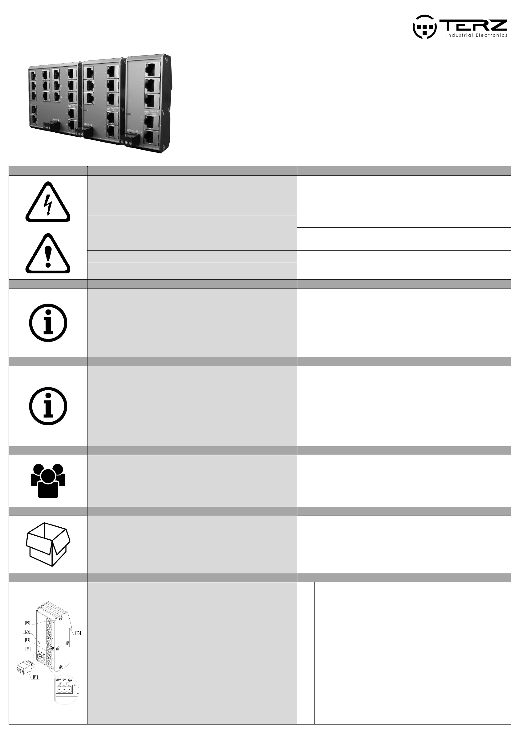
Gerätebeschreibung
Device description
[A]
[B]
[C]
[D]
[E]
[F]
[G]
LED „Power“
LED „L/A 10/100 Mbit/s“
LED „L/A 1000 Mbit/s“ (nur bei Full Gigabit Switches)
RJ45-Schnittstellen
Buchse Spannungsanschluss (Versorgungsspannung + Funktionserde)
Spannungsklemme
Halter für die Hutschienenmontage (NITE-RF) / Seitenplatten für Wandmontage
(NITE-RW)
[A]
[B]
[C]
[D]
[E]
[F]
[G]
LED „Power “
LED „L/A 10/100 Mbit/s“
LED „L/A 1000 Mbit/s“(only for Full Gigabit products)
RJ45-interfaces
Jack power supply (supply voltage + functional earth)
Power supply connector
retainer for DIN rail mounting (NITE-RF) / side plates for wall-mounting (NITE-RW)

Einbau und Ausbau NITE-RF
Installation and Deinstallation NITE-RF
Einbau
1. Das Gerät und das Zubehör auspacken und auf Vollständigkeit überprüfen (siehe
„Lieferumfang“).
2. Die gelieferten Komponenten auf einwandfreien Zustand überprüfen.
3. Das Gerät angewinkelt mit obiger Nut des Hutschienenhalters [G] auf Hutschiene
hängen.
4. Das Gerät von oben nach unten auf die Hutschiene kippen, bis es einrastet.
Installation
1. Unpack the device and accessories and check for completeness (see "scope of delivery").
2. Check the delivered components for proper condition.
3. Put the product angled to the DIN rail and put the upper nut on the top of the DIN rail.
4. Push the device from top down to the DIN rail until the retainer locks on the DIN rail.
Ausbau
1. Das Gerät spannungsfrei schalten.
2. Die Spannungsklemme [F] vom Gerät lösen.
3. Alle Datenkabel vom Gerät lösen [D].
4. Die Hutschienenverrastung unter dem Gerät mit einem geeigneten Schraubendreher
nach unten bewegen.
5. Das Gerät von unten nach oben von der Hutschiene kippen.
6. Das Gerät von der Hutschiene nehmen.
Deinstallation
1. De-energize the device.
2. Disconnect the plug [F] from the Power supply jack of the device.
3. Disconnect all data cables from the device [D].
4. Unlock the retainer below the device with a suitable tool.
5. Flip the device from down to top from the DIN rail.
6. Remove the device from the DIN rail.
Einbau und Ausbau NITE-RW
Installation and Deinstallation NITE-RW
Einbau
1. Das Gerät und das Zubehör auspacken und auf Vollständigkeit überprüfen (siehe
„Lieferumfang“).
2. Die gelieferten Komponenten auf einwandfreien Zustand überprüfen.
3. M4 Löcher für die Wandmontage (siehe Skizze) vorbereiten. Auf jeder Seite mindestens 1
Loch zur Befestigung vorbereiten.
4. Die Lochabstände sind der Skizze zu entnehmen.
5. Das Gerät mit einer Linsenkopfschraube passend zum Untergrund mit Hilfe der
Seitenplatte [G] an der Wand befestigen.
6. Die Schraube mit einem Drehmoment von mindestens 2 Nm festziehen.
Installation
1. Unpack the device and accessories and check for completeness (see "scope of delivery").
2. Check the delivered components for proper condition.
3. Prepare M4 holes for wall mounting (see sketch). Prepare at least 1 hole on each side for
wall mounting.
4. The hole distances are shown in the sketch.
5. Fix the device at the wall using a panhead screw fitting to the ground using the side plate
[G].
6. Tighten the screw with a torque of at least 2 Nm.
Ausbau
1. Das Gerät spannungsfrei schalten.
2. Die Spannungsklemme [F] vom Gerät lösen.
3. Alle Datenkabel vom Gerät lösen [D].
4. Die Schrauben lösen und das Gerät von der Wand/Untergrund nehmen.
Deinstallation
1. De-energize the device.
2. Disconnect the plug [F] from the Power supply jack of the device.
3. Disconnect all data cables from the device [D].
4. Loosen the screws and remove the device from the wall/surface.
Elektrischer Anschluss
Electrical Interface
Nur Kupferleitungen mit zulässigem Temperaturbereich (-40 °C bis +80 °C) als
Anschlusskabel verwenden.
Only use copper cables with the valid temperature range (-40°C up to +80°C) as connection
cable.
Spannungsklemme
•3-polig, steckbarer Schraubanschluss (+ - FE)
•Anzugsmoment der Schrauben der Schraubklemmen 0,5...0,8 Nm (4,5...7 lbs-in)
•Leiterquerschnitt 0,75 mm² ... 2,5 mm² (AWG 20 - 13)
Spannungsklemme
Belegung
Pol 1
24 VDC/VAC (50/60 Hz)
Pol 2
0 V
Pol 3
Funktionserde
Power supply plug
•3-pole pluggable, screw connector (+ - FE)
•Tightening torque of the screws of the power supply 0.5...0.8 Nm (4.5...7 lbs-in)
•Wire diameter 0,75 mm² ... 2,5 mm² (AWG 20 - 13)
Power Supply Plug
Pinning
Pole 1
24 VDC/VAC (50/60 Hz)
Pole 2
0 V
Pole 3
Functional Earth
RJ45-Schnittstellen
•Die Ethernet-Kabel mit RJ45-Stecker in beliebige RJ45-Schnittstellen [D] stecken.
•Den RJ45-Stecker auf festen Sitz überprüfen.
RJ45-interfaces
•Connect the Ethernet cables with RJ45-connectors to any RJ45-interfaces [D].
•Proof the RJ45-plug for proper connection.
10 / 100 Base-T(X)
1000 Base-T
MDI
connection
MDI-X
connection
MDI
connection
MDI-X
connection
1
TX+
RX+
BI_DA+
BI_DB+
2
TX-
RX-
BI_DA-
BI_DB-
3
RX+
TX+
BI_DB+
BI_DA+
4
-
-
BI_DC+
BI_DD+
5
-
-
BI_DC-
BI_DD-
6
RX-
TX-
BI_DB-
BI_DA-
7
-
-
BI_DD+
BI_DC+
8
-
-
BI_DD-
BI_DC-
LED Status
•Die Beschreibungen für [C] gelten nur für Full Gigabit Switches.
LED status
•The descriptions for [C] are only valid for Full Gigabit Switches.
LED Status
Bemerkungen
LED [A] leuchtet grün
Versorgungsspannung liegt an
LED [B] aus
Kein Link
LED [B] leuchtet grün
Link aktiv 10/100 Mbit/s
LED [B] blinkt grün
Link aktiv & Datentransfer 10/100 Mbit/s
LED [C] aus
Kein Link
LED [C] leuchtet grün
Link aktiv 1000 Mbit/s
LED [C] blinkt grün
Link aktiv & Datentransfer 1000 Mbit/s
LED Status
Remarks
LED [A] lighted green
Power supply attached
LED [B] off
No Link established
LED [B] lighted green
Link active 10/100 Mbit/s
LED [B] blinking green
Link active & data transfer 10/100 Mbit/s
LED [C] off
No Link established
LED [C] lighted green
Link active 1000 Mbit/s
LED [C] blinking green
Link active & data transfer 1000 Mbit/s
Inbetriebnahme
Start-Up
1. Zunächst den korrekten / eingerasteten Sitz des Gerätes auf der Hutschiene prüfen.
2. Die Spannungsversorgung an der Spannungsversorgungsbuchse [E] anschließen.
3. Die Datenkabel an den RJ45-Schnittstellen [D] anschließen und auf korrekte Funktion
prüfen; hierzu die Tabelle „LED Status“ beachten.
4. Bei Fehlfunktion bitte das Kapitel „Erste Hilfe bei Fehlfunktion“ beachten.
1. At first check, if the device is correctly mounted on the DIN rail.
2. Connect the power supply to the power supply jack [E].
3. Connect the data cables to the RJ45-interfaces [D] and check for correct function; refer to
the table "LED Status".
4. In case of malfunction, please refer to the chapter "First aid in case of malfunction".
Erste Hilfe
First aid
1. Den Spannungsanschluss überprüfen.
2. Die LED-Aktivität überprüfen; siehe Tabelle „LED Status“.
3. Netzwerkkabel überprüfen: korrekter Sitz? Link aufgebaut? Eventuell durch Stecken auf
einen anderen Port den Fehler auf einen Port reduzieren.
4. Kabel tauschen, um ein fehlerhaftes Kabel auszuschließen.
5. Bei weiteren Fragen oder andauernder Fehlfunktion kontaktieren Sie bitte:
support@terz-ie.com
1. Check the nominal voltage connection.
2. Check the LED activity, refer to the table “LED status”.
3. Check the data cables; Are they correctly fitted? Is there a link established? Try to activate
another port, to check if only one port has malfunction.
4. Change the cable, to be sure the cable has no malfunction.
5. For further questions or remaining malfunction, please contact: support@terz-ie.com
TERZ Industrial Electronics GmbH
Gewerbepark 5a
D-49143 Bissendorf, Germany
Tel. +49 5402 60 80 970
Fax +49 5402 60 80 979
Hinweis: Technische und inhaltliche Änderungen dieses Dokuments ohne Ankündigung sind vorbehalten. TERZ übernimmt keinerlei Verantwortung
oder Haftung für eventuelle Fehler oder Ungenauigkeiten in diesem Dokument. Alle Rechte an diesem Dokument und dessen Inhalte behalten wir uns
vor. Vervielfältigung, Verwendung des Inhalts oder die Bekanntgabe an Dritte in jedweder Form ist ohne schriftliche Genehmigung durch TERZ nicht
gestattet.
Copyright© 2020 TERZ Industrial Electronics GmbH. Alle Rechte vorbehalten.
Note: We reserve the right to make technical changes to this document without prior notice. TERZ assumes no responsibility or liability for any errors or
inaccuracies in this document. All rights to this document and its contents are reserved. Duplication, use of the content or announcement to third parties
in any form is not permitted without written permission from TERZ.
Copyright © 2020 TERZ Industrial Electronics GmbH. All rights reserved.
This manual suits for next models
1
Other TERZ Switch manuals


Popular Switch manuals by other brands

CyberData
CyberData 011539 Installation quick reference

hager
hager 04011 User instructions

D-Link
D-Link DGS-1005D - Switch Quick installation guide

AU
AU SAE J1939 user manual

ZyXEL Communications
ZyXEL Communications MGS-3712 user guide

Eaton
Eaton TriSync COOPER POWER MN230011EN Installation and operation instruction

Siemens
Siemens 3VA9978-0AB2 operating instructions

ASTEK
ASTEK A51606-SW quick start guide

Sony
Sony CAV-CVS12ES - Component Video Switcher Specification sheet

Cedes
Cedes ObjectC 100 I/O Programmer's guide

Cisco
Cisco C9200CX-8P-2X2G-A Hardware installation guide

Cisco
Cisco 3750 - Catalyst EMI Switch datasheet


