Tesla TI50A User manual

Tesla™TI50A
DC Power Supply
User Manual
Power Anytime, Anywhere
Tesla Industries, Inc.
101 Centerpoint Blvd.
New Castle, DE 19720
(302) 324-8910 Phone
(302) 324-8912 Fax
www.teslaind.com
Built Smart...Proven Tough

NOTE: All users must read this entire manual prior
to operating the TI50A DC Power Supply.
The TI50A DC Power Supply is a limited maintenance-free and sealed unit. No repairs are authorized.
Warranty will be voided if unit is tampered with in any way, or if unauthorized repairs are made. For technical
support please contact:
TESLA™ INDUSTRIES INCORPORATED
101 CENTERPOINT BLVD.
CENTERPOINT INDUSTRIAL PARK
NEW CASTLE, DELAWARE 19720
PHONE: (302) 324-8910
FAX: (302) 324-8912
WEBSITE: www.teslaind.com
EMAIL: tesla1@teslaind.com
Improper use or failure to follow instructions in this user manual can result in unit damage and/or injury or
death by electrical shock.
Any attempts to open or examine the inside of the TI50A DC Power Supply via a tool or device (borescope,
probe, etc.) can result in unit failure and/or injury by electrical shock. This unit is maintenance free and
should not be opened or disassembled for any reason.
Always protect the unit from short circuit.
Shipping Hazards: None.
No part of this manual may be reproduced or transmitted in any form or by any means, electronic or
mechanical, including photocopying, recording, or any information storage and retrieval system, without prior
written permission from Tesla™ Industries, Inc.
Copyright © 2016 by Tesla™ Industries, Incorporated. All rights reserved.
NOTE
!Unit is not rated for engine starting.
It is to be used for ground maintenance only.
Shock Hazard Potential
CAUTION
09-01-16

TI50A DC Power Supply
Table of Contents
Section 1 – Safety Review 1
1.1 – Safety Notices 1
1.2 – Symbols 1
1.3 – Hazards 2
1.4 – Important Safety Precautions 3
1.5 – Extreme Environments 3
Section 2 – Product Overview 4
2.1 – Introduction 4
2.2 – Indication of Terms: Shall, Should, and May 4
2.3 – Front Panel Overview 5
2.4 – General Specications 6
2.5 – Physical Dimensions 7
2.6 – Airow Ports 7
2.7 – Operating Position 8
2.8 – AC Input Circuit Breakers 9
2.9 – 24 Vdc Output Connector 9
2.10 – DC Output Circuit Breaker 9
2.11 – Input Voltage Selector Switch 10
2.12 – AC Input Receptacle 11
2.13 – “Available Power” LED Indicator 11
Section 3 – Operating Procedures 12
3.1 – Operating Procedures 12
3.1 – General 12
3.2 – Operating Limits and Restrictions 12
3.4 – Environmental 13
3.5 – Normal Functional Test Procedures 14-15
3.6 – Pre-Operation 16
3.7 – Transporting Unit 16
3.8 – Regulated 28.5 Vdc Ground Power 18

TI50A DC Power Supply
Section 4 – Post Operation 18
4.1 – General 18
4.2 – After Use 18
Section 5 – Unit Care and Maintenance 19
5.1 – Unit Care 19
5.2 – Unit Servicing 20
5.3 – Packaging and Shipping 20
Section 6 – Troubleshooting and FAQ 21
6.1 – Frequently Asked Questions 21-22
6.2 – Basic Usage/Operation Questions 22
6.3 – Basic Troubleshooting 23
Section 7 – Optional Accessories 24
7.1 – Shipping Case 24
7.2 – Protective Covers 24
7.3 – Tesla™ AC Line Cords 24
7.4 – Cobra™ DC Replacement Contacts and Tools 25
7.5 – Transport Dolly 25
Appendix A 26-30
Repair Request Form 31

TI50A DC Power Supply
Abbreviations and Symbols
Abbreviations that may be used within the text, headings and titles of this manual.
LIST OF ABBREVIATIONS
Abbreviation Defi nition
ac Alternating Current
AFT Air ow Technology
AWG American Wire Gauge
amp or A Ampere
cont Continuous
°C Degree Celsius
°F Degree Fahrenheit
dc Direct Current
EFF Ef ciency
ft Feet
FWD Forward
GPU Ground Power Unit
Hr Hour
Hz Hertz
kg Kilograms
kHz Kilohertz
kW Kilowatts
LED Light Emitting Diode
max Maximum
MΩ megaohm
min Minimum
MPU Micro Power Unit
NEMA National Electrical Manufacturers Association
Ω ohm
PF power factor
PFC power factor correction
rms root-mean-square
THD Total Harmonic Distortion
TMDE Test, Measurement, & Diagnostic Equipment
UAV Unmanned aerial vehicle
Vac Volts, Alternating Current
Vdc Volts, Direct Current
W watts

TI50A DC Power Supply 1
Figure 1.2.1 – Different types of hazard and caution symbols
1.1 - Safety Notices
Safety notices appear throughout this manual to alert the user to important information regarding proper
installation, operation, maintenance and storage of the unit. These notices, as illustrated below, contain a
key word that indicates the level of hazard and a triangular icon that indicates the speci c type of hazard.
WARNING Indicates a condition, operating procedure or practice, which if not
adhered to could result in serious injury or death.
CAUTION Indicates a condition or operating procedure, which if not strictly
adhered to could result in damage or destruction of equipment.
NOTE Indicates a condition, operating procedure or practice, which is
essential to highlight.
1.2 - Symbols
The following symbols will appear within the warning triangles to alert the user to the speci c type of danger
or hazard.
General Warning Electrical Hazard Explosion Hazard Fire Hazard
Battery Warning Guard from Moisture
!
Section 1 – Safety Review
!
!
!

TI50A DC Power Supply
2
1Safety Review
1.3 – Hazards
WARNING Shock Hazard Potential
Severe injury or death from electrical shock can occur when damp electrical plugs are connected to the
unit. Before making any connections, turn off unit. Failure to use proper grounding can cause potential
shock hazard! In different countries, the power cord may require the use of a plug adapter to achieve plug
style compatibility for operation. Use only adapters with proper grounding mechanism.
CAUTION Unit Damage Potential
Severe injury or death from electrical shock may occur, if either user
or the unit is wet, while the unit is connected to a power source. If the
unit has come into contact with water, disconnect ac power from the ac
source. If AC Input Circuit Breaker has tripped due to water in ltration,
DO NOT try to reset it with the ac line voltage attached.
Figure 1.3.1 – Proper Ground
Grounded Plug with Grounding Pin
Figure 1.3.2 – Proper Ground
Adapter with Grounding Mechanism
(Secured to Outlet)
Figure 1.3.3 – Improper Ground
Plug with No Grounding Pin
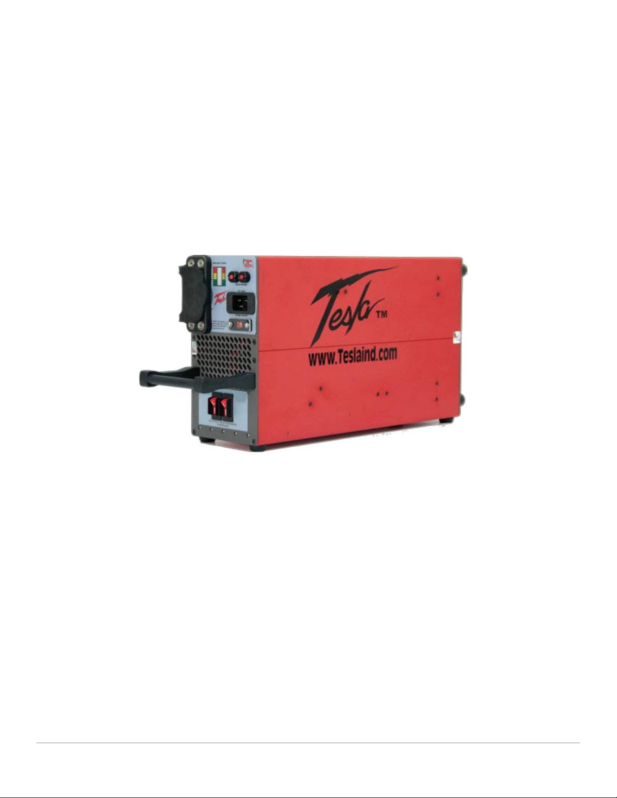
The use of unapproved ac power will damage the unit. Check the
Input Voltage Selector Switch window (outlined in blue) to ensure
the switch setting (115V or 230V) matches the ac power source
(hangar wall, ight line ac power) prior to connecting the unit for
recharging.
Figure 1.3.4 – TI50A DC Power Supply
Input Voltage Selector Switch

TI50A DC Power Supply 3
1
Safety Review
1.4 – Important Safety Precautions
WARNING Fire/Explosion Hazard Potential
Severe injury or death from re or explosion can occur if electrical sparks are produced near fuel vapors. DO
NOT CONNECT ac power supply WHILE FUELING. AC power functions of unit shall not be operated during any
fuel handling operation. Power output is restricted to dc power only.
1.5 – Extreme Environments
CAUTION Unit Damage Potential
The unit’s charger temperature switch automatically disables the unit when the internal temperature exceeds
150°F (65°C). This protects the unit from overheating and damage. If the unit shuts down, move the unit
into a cooler environment such as shade or air conditioning when possible. Perform a full function test, after
the unit has been allowed to cool, prior to use.

TI50A DC Power Supply
4
Figure 2.1.1 – TI50A DC Power Supply
2.2 – Indication of Terms: Shall, Should, and May
Within this technical manual the word “shall” is used to indicate a mandatory requirement for proper operation
and warranty purposes. The word “should” is used to indicate a non-mandatory but preferred method of
accomplishment. The word “may” is used to indicate an acceptable method of accomplishment.
Section 2 – Product Overview
2.1 – Introduction
Thank you and congratulations on the purchase of your new TI50A DC Power Supply.
The TI50A DC Power Supply is intended to provide dc electrical ground power for aircraft ight line and
maintenance ground support operations. The unit is designed to provide 28.5 volts dc electrical support
for ground maintenance, avionics/electrical troubleshooting and testing. The observance of procedures,
limitations and performance criteria is essential to ensure peak operating efciency and to maximize
operational capabilities and life of the TI50A DC Power Supply.
This manual contains the complete operating instructions and procedures for the TI50A DC Power Supply
that the end user will need to safely and efciently operate this DC Power Supply.

TI50A DC Power Supply 5
2
Product Overview
2.3 – Front Panel Overview
24 Vdc Output Connector1. – Provides
50 amps continuous @ 28.5 Vdc (when
plugged into ac power)
Output Connector Protective Cover2. -
Protects Output Connector from dust
and foreign materials.
Air Intake Ports3. – Provide airow for
cooling internal electronics.
Carrying Handle4. – Allows for easy
transport of unit.
AC Input Circuit Breakers5. – Trip if over-
current fault condition occurs.
“Available Power” Meter6. – Displays
status of power output.
AC Input Connector7. – Connects to
Single Phase 100-260 Vac line voltage.
Input Voltage Selector Switch8. – Allows
unit to operate within voltage range of
either 100-130 Vac or 200-260 Vac.
DC Output Breakers9. - Trips if an over-
current condition occurs.
6
5
7
8
9
3
4
1
2

TI50A DC Power Supply
6
2Product Overview
2.4 – General Specications
Electrical
AC Input Power:
Operates from Single Phase 100-260 Vac, 50/60 Hz•
20 amps @ 120 Vac - 2400 Watts•
10 amps @ 240 Vac - 2400 Watts•
DC Output Power:
50 amps continuous @ 28.5 Vdc - 1425 Watts•
Size:
21.25” long x 5.2” wide x 10.56” high•
539.7mm x 132.1mm x 268.25mm•
Weight
15.85 lbs (7.19 kg)•
Operating Temperature:
-40°C to +55°C (-40°F to 131°F) with AC power•
Storage Temperature:
-65°C to +105°C (-85°F to 221°F)•

TI50A DC Power Supply 7
2
Product Overview
2.5 – Physical Dimensions
2.6 – Airow Ports
CAUTION Damage may occur if the TI50A DC Power Supply’s air intake or outlet
ports are obstructed. Ensure that ports are clear at all times.
When the TI50A DC Power Supply is plugged into ac power, the internal cooling system will efciently regulate
unit temperature regardless of load. At room temperature (+77°F) the exhaust air will not exceed the ambient
temperature by more than 5°F. In more extreme temperatures (greater than 90°F) the exhaust air will not
exceed the ambient temperature by more than 10°F.
FRONT VIEW SIDE VIEW
5.20 [132.1]
10.20 [259.0]
21.25 [539.7]
18.75 [476.2]
Figure 2.5.1 – TI50A DC Power Supply Physical Dimensions
Figure 2.6.1 – Air intake, exhaust ports and internal air circulation

TI50A DC Power Supply
8
2Product Overview
2.7 – Operating Positions
The TI50A DC Power Supply can be operated in both the horizontal (Figure 2.7.1) and vertical (Figure 2.7.2)
positions as shown. Make sure that the airow is not obstructed from air intake (gure 2.7.3) and outlet
(Figure 2.7.4).
Figure 2.7.2: Vertical Position
Figure 2.7.1: Horizontal Position
Figure 2.7.3: Front Inlet Figure 2.7.4: Rear Outlet

TI50A DC Power Supply 9
2
Product Overview
Figure 2.8.1 - AC Input Circuit Breaker (outlined in blue)
2.8 – AC Input Circuit Breaker
The AC Input Circuit Breaker is located above the AC Input Connector. When the circuit breaker has been
tripped, the red button will pop out. In the event that the breaker trips:
Disconnect the ac and dc connectors. (Unplug ac line cord on military unit.)1.
Wait for a minimum of 60 seconds.2.
Reset breaker by pressing red button.3.
Reconnect ac and dc connections to the unit. (Plug in ac line cord on military unit.)4.
The unit should power up automatically. If the breaker continues to trip, return the unit to Tesla™ Industries
for repair.
2.9 – 24 Vdc Output Connector
The 24 Vdc Output Connector provides 50 amps continuous @ 28.5 Vdc (when plugged into ac power).
When the Output Connector is not in use, cover the receptacle with the Protective Cover (see Figure 2.9.1) to
protect the Output Connector from dust and foreign matter.
Open Closed
Figure 2.9.1 - 24 Vdc Output Connector Protective Cover
2.10 – DC Output Circuit Breaker
The DC Output Circuit Breaker is located on the bottom section on the front panel. Both Circuit Breakers
on together provides 70 Amps max. When the circuit breaker has been
tripped, the rocker switch will ip off. If the Circuit Breakers trip, it has
exceeded the 70 amps max limit.
If the breaker has tripped:
Lower the amperage the unit is pulling below 70 amps.1.
If you are certain your load is below 70 amps and the Circuit2.
Breakers continue to trip, return the unit to Tesla™ for repair.

TI50A DC Power Supply
10
2Product Overview
Figure 2.11.2 - Unscrew Protective Cover Figure 2.11.3 - Select Voltage
Figure 2.11.1 Input Voltage Selector Switch (outlined in blue)
Changing Input Voltage Selector Switch
To change the input voltage from 115 Vac to 230 Vac, simply follow these steps:
With cross tip screwdriver, remove one screw and rotate the clear protective cover to one side.1.
(see gure2.11.2)
Flip the switch to read 230V. (see gure 2.11.3)2.
Rotate cover back into place. Replace and tighten screw.3.
2.11 – Input Voltage Selector Switch
The Input Voltage Selector Switch allows the unit to operate safely within the expected voltage range of either
100 - 130 Vac or 200 - 260 Vac.
!The 115 Vac setting accommodates the voltage range of 100-130 Vac.
The 230 Vac setting accommodates the voltage range of 200-260 Vac.
NOTE
CAUTION
!Do not plug unit into 230 Vac when Input Voltage Selector Switch is
set on 115 Vac.
NOTE
Do not overtighten Selector Shield screws. Be sure star locks are on
screws and snug the screw. Overtightening will damage the Selector
Shield.
!

TI50A DC Power Supply 11
2
Product Overview
Figure 2.13.1 - “Available Power” LED Indicator
location (outlined in blue)
A
VAILABLE POWER AVAILABLE POWER AVAILABLE POWER
Figure 2.13.2 - “Available Power” LED Indicating power status
2.12 – AC Input Receptacle
The AC Input Receptacle is designed to plug into either a standard 120 or 240 Vac outlet with the supplied line
cord (see Figure 2.10.2. and see also Section 8.3 for the proper line cord for your country and region). Please
ensure that the unit is properly grounded at all times (see Section 1.3 for proper grounding techniques).
Figure 2.12.1 - AC Input Receptacle location
(outlined in blue)
2.13 – “Available Power” LED Indicator
The “Available Power” LED Indicator provides a way for the user to visually see the amount of current load
that the TI50A is supplying. This lets the operator know if the maximum current load is being exceeded.
Current loads up to 50 amps will show one or two green bars. If the red bars are illuminated, the unit is
supplying less than 24 Vdc. Reduce current load to prevent damage to the unit.
Figure 2.12.2 AC North American Line Cord
A
VAILABLE POWER AVAILABLE POWER AVAILABLE POWER
No PowerFull Power

TI50A DC Power Supply
12
Section 3 – Operating Procedures
3.1 – Operating Procedures
This section covers normal procedures and steps necessary to ensure safe and ef cient operation of the
unit.
NOTE
!When not in use, the unit should always remain plugged into a suitable ac
power source to ensure operational readiness at all times.
NOTE
!If current demand exceeds 25 amps, converter output voltage will drop below
28.5 Vdc and two or more LED status indicator bars will illuminate. If all
LED status indicator bars illuminate, both the converter and power cells are
supplying 24 Vdc power output.
3.2 – General
The user should be well-versed in both pre-use and functional checks for correct operations of this unit.
Knowledge of the operating limits, restrictions, performance, unit capabilities and functions aids in correct
and safe operations. Compliance with the instructions in this manual affect operational safety as well as the
warranty of the unit.
3.3 – Operating Limits and Restrictions
The minimum, maximum and normal operating ranges result from careful engineering and evaluation of test
data. These limitations must be adhered to during all phases of operation.
3.4 – Performance
Refer to Section 7, PERFORMANCE DATA to determine the capability of the unit. Consideration must be given
to changes in performance resulting from variations in ambient temperature, mode of operation, state of
charge (with or without ac power), and aircraft dc bus system inef ciency (voltage drops).
3.5 – Engine Starting Power
The unit should always be charged above 80% prior to ground support engine starting. However, circumstances
may exist during use where unit recharge is not readily available and immediate external engine starting
power is required. The following provides minimum states of charge necessary to provide ample power for
an ef cient engine start under speci c current load demands.
ENGINE START PEAK CURRENT Requirements MINIMUM CHARGE
Under 650 peak starting amps 0-50% charged
650 - 850 peak starting amps 50-60% charged
850 - 1000 peak starting amps 60-70% charged
1000 - 1200 peak starting amps 70-80% charged
1200 - 1500 peak starting amps 80-100% charged
ENGINE START PEAK CURRENT Requirements MINIMUM CHARGE
Under 1200 peak starting amps 0-40% charged
1200 - 1500 peak starting amps 40-50% charged
1500 - 1800 peak starting amps 50-60% charged
1800 - 2100 peak starting amps 60-70% charged
2100 - 2400 peak starting amps 70-80% charged
2400 - 3000 peak starting amps 80-100% charged
If current demand exceeds 50 amps, power supply voltage will drop below
28.5 Vdc and two or more LED status indicator bars will illuminate. If all LED
status indicator bars illuminate, the converter is supplying 24 Vdc power
output.

TI50A DC Power Supply 13
3
Operating Procedures
3.7 – Environmental
If the unit is exposed to moisture, preventive measures and precautions shall be taken to:
A. Prevent accumulation of moisture on ac and dc connectors/receptacles
B. Minimize moisture entering forward inlet and aft outlet cooling fan vent ports
Unit inlet and outlet vent ports shall be covered from exposure. Unit shall be kept horizontal.
Recommendations include a Protective Rain Cover to guard the unit from moisture (see Section 8). The limits
and operational constraints listed below shall apply for the following environmental (weather) conditions:
WARNING Operating any electrical equipment in the presence of moisture creates
possible safety hazards and/or potential for equipment damage. Every
effort has been made, within the scope of existing technology to prevent
foreseeable safety hazards and make the unit moisture resistant to prevent
damage or failure.
Conditions With
Raincover Without Raincover
Heavy or steady rain:
Precipitation falling with an intensity in excess of 0.30 inch
(0.76 cm) or continuously between 0.30 and 0.10 inch per hour.
OK OPERATION NOT RECOMMENDED
Light rain, drizzle or sleet:
Precipitation falling on a continuous basis between 0.10 inch
and less than 1/50 inch (0.5 mm) per hour
OK DC OPERATIONS ONLY
Heavy or steady snow:
Generally meaning an accumulation between 4 inches and less
than 1 inch in a 12 hour period.
OK OPERATION NOT RECOMMENDED
Light snow:
Snow falling intermediately with little or no accumulation.
OK DC OPERATIONS ONLY
Fog: OK OK
3.7 – Environmental
If the unit is exposed to signi cant moisture, preventive measures and precautions shall be taken to:
A. Prevent accumulation of moisture on ac and dc connectors/receptacles
B. Minimize moisture entering forward inlet and outlet cooling fan vent ports
When not in use, unit inlet and outlet vent ports shall be covered from exposure. Unit shall be kept
horizontal.
WARNING
Operating any electrical equipment in the presence of moisture creates possible
safety hazards and/or potential for equipment damage. Every effort has been
made, within the scope of existing technology to prevent foreseeable safety
hazards and make the unit moisture resistant to prevent damage or failure.
3.4 – Environmental
Figure 3.4.1 – Unit with raincover. Ordering info on page 24.

TI50A DC Power Supply
14
3Operating Procedures
3.5 – Normal Function Test Procedures
This section concerns with “normal function” test procedures, and
includes all steps necessary to ensure that the unit is operating within
specied para meters prior to use. A digital multimeter (an example
is shown in Figure 3.5.1) capable of measuring dc and ac voltage
and resistance will be required to perform some of the tests. These
functional test procedures should become routine.
Figure 3.5.1 – Digital Multimeter
Figure 3.5.3 – Testing DC
Receptacle
Check Unit for Evidence of Damage
Check for dents, punctures, case distortion or misalignment, and cracked or loose connectors. If no damage
is evident, proceed to the next step. If damage is evident, contact Tesla™ Industries, Inc.
Check DC Voltage Reading at DC Receptacle Terminals
To verify that the power supply is functioning normally, set the digital multimeter to measure dc voltage.
Turn the unit on. Turn on both DC Output Circuit Breakers (Figure 3.6.2). As shown in Figure 3.6.3, place the
positive probe (red) on the positive post of the dc output connector and the negative probe on the negative
post. The multimeter display should read approximately 28.5 Vdc (± 0.5 Vdc). NOTE: To test each Circuit
Breaker individually, turn only one of the Circuit Breakers on at a time when testing. As in the previous test,
the multimeter display should read approximately 28.5 Vdc (± 0.5 Vdc).
Figure 3.5.2 – DC Output Circuit
Breakers has a 70 amps max

TI50A DC Power Supply 15
3
Operating Procedures
Check Unit Internal Resistance (Test for Shorts)
2. Turn on both DC Circuit Breakers
before testing.
4. Move the positive probe to the dc
negative post. Multimeter should
read greater than 10 MΩ.
5. Move the positive probe to the fas-
tener screw on the dc receptacle.
Multimeter should read less than
1Ω.
2. Place the positive probe to the fas-
tener screw on the dc receptacle.
Move the negative probe to the dc
negative post. Multimeter should
read 0 Volts.
3. Place the negative probe to the
fastener screw on the dc recep-
tacle. Move the positive probe to
the dc positive post. Multimeter
should read 0 Volts.
1. Set multimeter to Ohms.
1. Set multimeter to Volts.
NOTE
!Unit should be disconnected from any ac power sources prior to testing.
3. Place the negative probe on the ac
ground post and the positive probe
to the dc positive post. Multimeter
should read greater than 10 MΩ.
Table of contents
Other Tesla Power Supply manuals