TESLICA M1H User manual
www.teslica.com
1
Let theide begin
User’s ManUal
www.teslica.com • [email protected]
Que laandonnée commence!
GUide de l’UtilisateUr
2
Let the ride begin!
SAFETY INSTRUCTIONS + NOTES
GUide de
l’UtilisateUr
paGe 15-28
ASSEMBLY
USE + MAINTENANCE
TROUBLESHOOTING
BIKE DIAGRAM + COMPONENTS
OPERATION + ADJUSTMENT
1.1 Safety instructions
1.2 Notes
3.1 Components for assembly
3.2 Installation of handle bar
3.3 Alignment and tightening of steering headset
3.4 Installation of pedals
3.5 Installation of front hub axle and wheel
3.6 Installation of headlight and front fender
3.7 Installation of bell, bottle holder and reectors
3.8 Setting of seat post and lock
3.9 Torque settings
5.1 Routine inspection before use
5.2 Maintenance
4.1 Power assist PAS system
4.2 Operation of your display
4.3 Battery and charging
4.4 Lighting and reectors
4.5 Saddle position and quick release
4.6 Braking system
4.7 Drive and gears
4.8 Suspension
4.9 Cargo rack
02
04
06
03
05
01
PAGE 3
PAGE 5
PAGE 7
PAGE 11
PAGE 14
PAGE 13
www.teslica.com
3
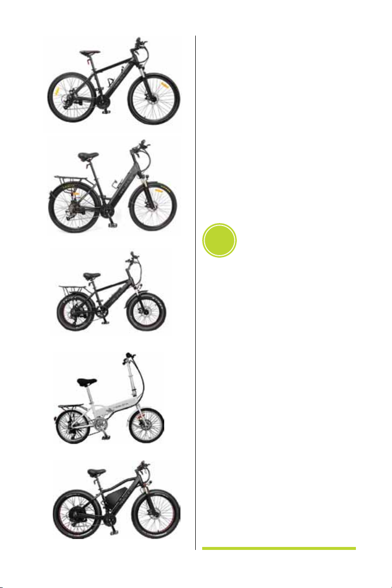
Model M1H
Model F1H
Model B1H
Model F2000
Model C1H
Power assisted bike – equipped with func-
tioning pedals and an electric motor of 500
watts or less, which cannot be exclusively
propelled by the motor, except in start up assis-
tance mode. Power assistance up to 32 km/h.
Power assisted bikes are equipped with an
electric motor, controller, battery and charger.
Electric bike 1 pc
Charger 1 pc
Tools 5 pcs
Manuals 2 pcs
1.1 Safety instructions
Please carefully read this entire
manual before using the electric bike
to avoid possible damages and or
personal injuries.
Preparations before riding: Wear your
tted helmet, gloves, proper footwear and
other protective gear to protect yourself
from injury in case of an accident.
Cycling conditions: Ambient temperature
of –10°C (14°F) to 35°C (95°F) no wind
and at roads
Max load: Electric bike 100kg and an addi-
tional 25kg on the cargo rack.
Avoid sustained usage in the following
conditions to conserve battery usage and
overall mileage: Frequent braking/accelera-
tion, hill starts, uphill, headwinds, muddy,
sandy or snow cover surfaces and over-
loading.
01 SAFETY INSTRUCTIONS
+ NOTES

4
Let the ride begin!
Battery storage: For terms over 30 days,
store the battery in a cool dry place at about
50-60% charge. You should charge it for 30
minutes every 30 days while being stored to
help maintain battery life.
Water damage: Bike parts are water
resistant and designed to function in the
rain. However, do not ride the bike in water
depths greater that the motor level. This will
result in permanent damage to the motor
and controller.
Our company is not responsible for any
losses that result from prohibited, unauthor-
ized demolition or alterations of the bike or
its components.
Be sure to discard the battery in an environ-
mentally friendly manor that coincides with
your local laws.
1.2. Notes
The Electric bike is designed on the basis
of the traditional bike in combination with
its special functions and uses in accor-
dance to market demand. At the time of
purchase ensure that a proper model and
size is chosen for your needs. Riders must
have previous cycling experience and
knowledge of local laws for electric bike
use on paths and roads. In order for your
safety and security, please pay attention
the following:
1. Prior to riding, ensure the front and rear
wheels are torque and locked in place,
ensure handle bars and headset are
properly aligned torqued, ensure pedals
are seated properly and torque, last,
ensure your seat post is adjusted to the
proper height and locked in place.
2. When using the electric assist while on
a steep slope, use the pedals as much
as possible to help reduce the surge
of current and extend battery life and
range.
3. Do not operate bike in water depths
greater than the motor level. This will
lead to a short circuit and permanent
damage of bike components.
4. Use only the dedicated charger. Always
plug the charger into the outlet power
supply rst, then into the battery.
5. Make sure to charge the battery is a well
ventilated area. Do not cover the battery
as this could lead to overheating and
possible re.
6. Please keep proper tire pressure to
ensure top performance of motor ef-
ciency, steering, braking, excessive wear,
rim damage and avoid punctures.
7. Riders should abide by local laws and
speed limits for both paths and roads.
Do not exceed 25kg load on cargo rack.
8. Use extreme caution when using front
brake at high speeds or going down hills
to avoid accidents.
9. For all safety related components contact
dealer. Be sure to purchase brand name
replacements and have all service work
completed by a certied bike mechanic.

www.teslica.com
5
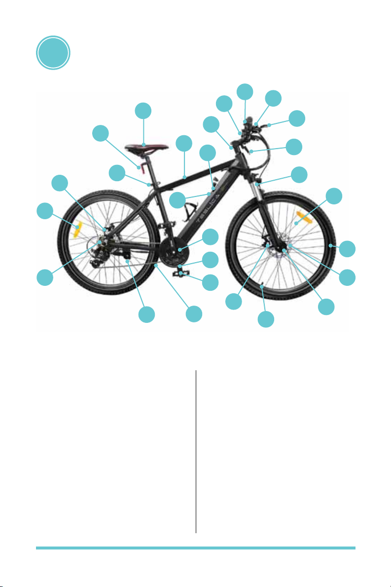
1. Frame
2. Seat post
3. Saddle
4. Stem
5. Handlebar
6. Gear shifter
7. Brake lever
8. Suspension front
9. Brake caliper
10. Hub
11. Disc brake
12. Valve
13. Tire
BIKE DIAGRAM + COMPONENTS
02
14. Speed sensor
15. Crank
16. Pedal
17. Chain
18. Freewheel
19. Motor
20. Rear wheel reector
21. Kick stand
22. Controller hidden in the frame
23. Battery hidden in the frame
24. Spoke
25. Front reector
26. LCD display
MOUNTAIN BIKE M1H BASIC STRUCTURE
17
21
20
18
19 2
27
3
1
23
22
4
56
26
7
25
8
24
12
13
11
10
16
15
14
9

6
Let the ride begin!
1. Frame
2. Seat post
3. Saddle
4. Stem
5. Handle bar
6. Gear shifter
7. Brake lever
8. Suspension front
9. Brake caliper
10. Disc brake
11. Hub
12. Rim
13. Tire
14. Speed sensor
15. Crank
16. Pedal
17. Chain
18. Freewheel
19. Motor
20. Spoke
21. Kick stand
22. Controller in frame
23. Battery
24. Reector
25. Cargo rack
26. LCD display
27. Bell
30. LED Headlight
CITY BIKE C1H BASIC STRUCTURE
17
21
20 8
18
19
2
25
29
3
1
22
23
4
5
27
6
26
7
28
30
12
13
24
10
11
16
15
14
9
www.teslica.com
7
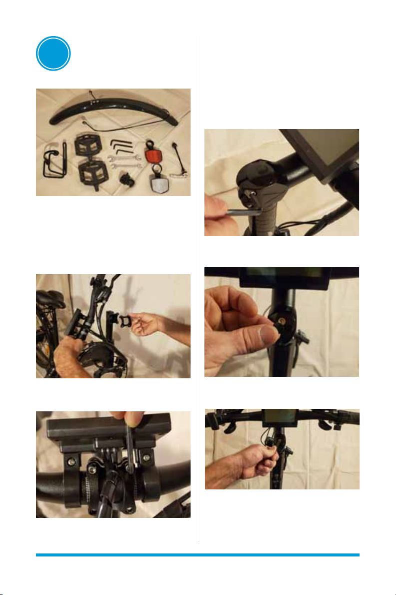
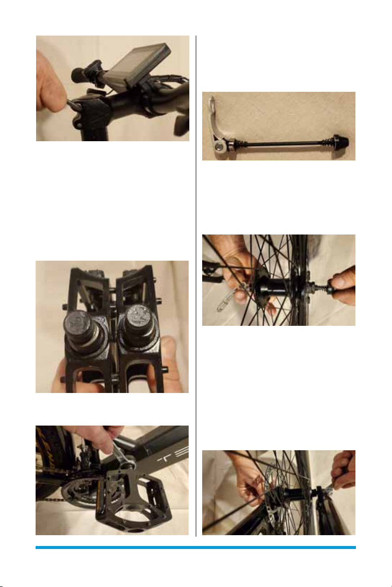
4. Tighten 4 bolts to proper torque setting
3.3 ALIGNMENT AND TIGHTENING
OF STEERING HEADSET
1. Use Allen key to slightly loosen 2 side
bolts on steering stem.
2. Remove black rubber cap on 1 headset
bolt
3. Tighten headset bolt to proper torque
setting and replace black rubber cap
4. Align goose neck and handle bars to
square with front suspension
5. Tighten 2 side bolts on steering stem to
proper torque setting (see image pg. 7)
03 ASSEMBLY
3.1 COMPONENTS FOR ASSEMBLY
Pedals, front fender, front axle/wheel, bell,
bottle holder and reectors
3.2 INSTALLATION OF HANDLE BAR
1. Remove protective wrapping from handle
bar
2. Use Allen key to remove 4 bolts from
goose neck cap
3. Use white indicators to align and center
handle bar under goose neck cap
8
Let the ride begin!
3.5 INSTALLATION OF FRONT HUB
AXLE AND WHEEL
1. Remove hand treaded nut and one
spring from axle
2. Insert axle through the hub. Add the
spring, then the hand treaded nut. Leave
very loose
3. Note: Be sure to install springs with
small tapered ends facing inwards
4. Wheel install: Align the disc brake and
axle, then slide into place on fork
5. Note: Make sure axle hand treaded nut
is loose for ease of alignment
6. Note: Ensure axle is seated correctly on
the frame.
7. Snug up the hand treaded nut then lock
down the quick release lever
3.4 INSTALLATION OF PEDALS
1. Remove pedals from protective
wrapping
2. Note: R for right side and L for left side
markings on treaded end
3. Note: Left side pedal is reverse thread.
Turn counter clockwise to tighten
4. Use wrench to tighten each side to
proper torque setting
www.teslica.com
9
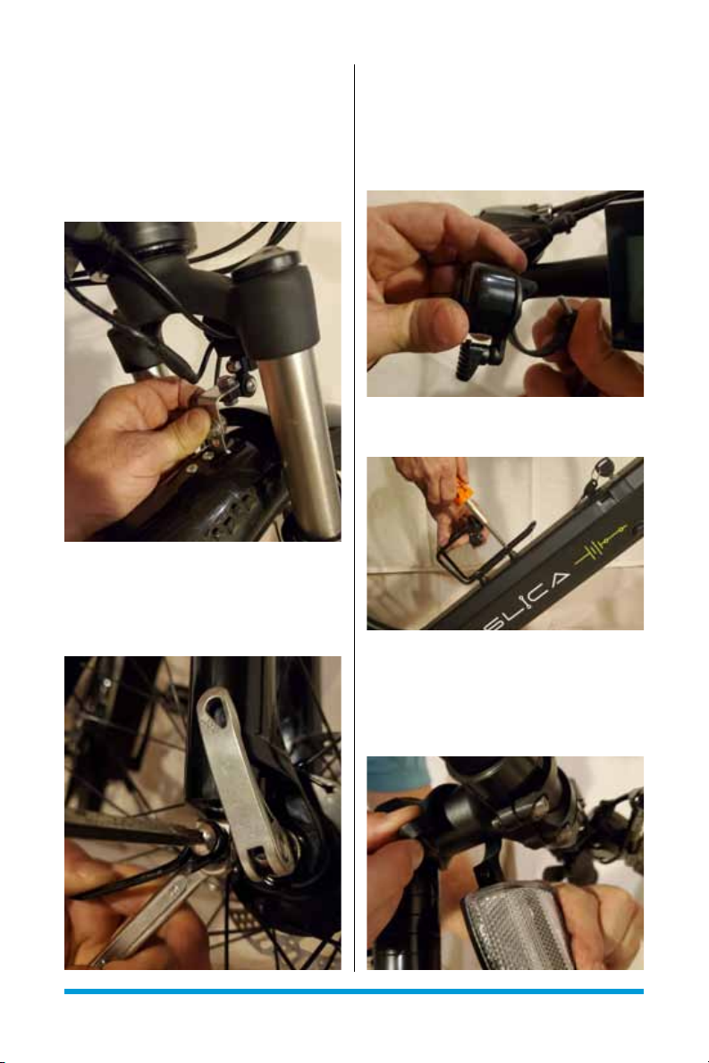
3.6 INSTALLATION OF HEADLIGHT
AND FRONT FENDER
1. Use wrench to remove 3 bolts from
suspension frame
2. Align the top center bolt through the
fender and headlight eyelet
3. Tread back into suspension frame and
tighten with wrench. Adjust alignment
4. Align and tighten side wire fender
supports with wrench and screwdriver
3.7 INSTALLATION OF BELL, BOTTLE
HOLDER AND REFLECTORS
1. Bell: Remove screw, open base and
afx on handle bar. Replace and tighten
screw.
2. Bottle holder: Remove 2 screws, align
bottle holder, replace and tighten screws
3. Reectors: Remove 1 screw, open base
and afx red one on seat post and white
one on horizontal section of gooseneck.
Replace and tighten screws. Adjust
reector angle
10
Let the ride begin!
3.8 SETTING OF SEAT POST AND
LOCK
1. Open quick release lock. Adjust seat to
proper height.
2. Use hand to adjust nut on left to achieve
proper tension. Lock down quick release
lever.
3. Note: Do not set seat height above max
warning
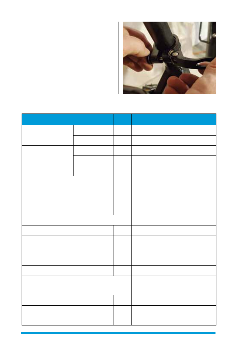
3.9 TORQUE SETTINGS
NAME OF CLAMP BOLTS STANDARD TORQUE / N.M
Bolt for handlebar 1 bolt / 2 bolts M5 10-12 N.M
M6 12-15 N.M
4 Bolts M4 4-6 N.M
M5 6-8 N.M
M6 8-10 NM
Handlebar expander bolt M6 12-15 N.M
M8 15-18 N.M
Handle bar stem and fork clamp bolt M5 8-10 N.M
M6 10-12 N.M
Sunower xing bolt 4-6 N.M
Saddle M6 10-12 N.M
M8 15-18 N.M
Seat-pillar xing bolt M4 8-10 N.M
M5 10-12 N.M
M6 12-15 N.M
Front wheel 25-30 N.M
Rear wheel 40-45 N.M
Rear rack M5 6-8 N.M
M6 8-10 N.M
Derailleur M10 8-10 N.M

www.teslica.com
11
4.1 POWER ASSIST PAS SYSTEM
The Peddle Assist System is designed
to deliver power by means of an
electric motor to assist you while you
are pedalling. As you pedal, a sensor
recognizes that moment and the motor
will automatically power up at a preset
level. This generally will allow you to go
further and faster on a typical ride.
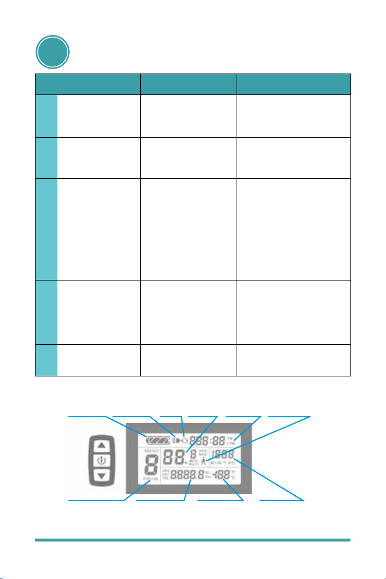
4.2 OPERATION OF YOUR DISPLAY
There are 5 power assist levels, 1 being
the lowest and 5 being the highest and
the max speed is 32km/h. Use the thumb
3 button controller to navigate on the
LCD screen. Hold the Power button for
3 seconds to power up the LCD screen.
The same process will turn power off. Use
the Up and Down buttons to control
the power assist level 1-5. To turn on
the LED headlight, hold the Up button
for 5 seconds. The same process will turn
power off. If there is no use for 5 minutes
the system will automatically shut down
to conserve power. You can operate the
bike on level 0 which is no assist but the
system will still track your distance, time
and speed. See KT3 – LCD manual for
more functions and info or go online.
04 OPERATION +
ADJUSTMENT
4.3 BATTERY AND CHARGING
The battery comes charged from the factory
however, it is not fully charged even if the
display reads a full charge. The battery
should be charged prior to rst use. Please
use the dedicated charger otherwise it could
lead to battery damage and or re. No
warranty will be provided for battery issues
as a result of neglect and misuse.
1. The battery may be charged on the bike
or removed
2. Battery removal – Use supplied key and
turn 90 degrees counter clockwise, then
pull up at top end of battery.
3. Verify the outlet power supplied voltage
is between 110-220 Volts
4. Note: Always plug the charger into the
outlet power supply rst, then into the
battery
5. The power indicator on the charger will
be red and once fully charged it will turn
green
6. Charging will take 5-6 hours. When
complete, disconnect the charger from
the battery, then unplug from the outlet
power supply
7. Note: A new bike may take as long as 9
hours for the rst deep charge
The battery should be charged in a cool,
spacious, ventilated environment. High
humidity may cause corrosion and high
temperatures may cause smoke or re.
Do not over charge the battery as it may
shorten its life expectancy.
When the battery is to be stored for a
period of time, discharge to about 50-60%
and keep it in a cool, dry place. You should
charge it for 30 minutes every 30 days.
Power Assist
Ration Gear &
Cruise Function
Battery
Capacity
Indicator
Backlights
& Headlight
Status Brake
Status
Vehicle
Speed
Display Running
Counter
6km/H Power
Assist Push
Function
Motor
Operation
Power
Environment
Temperature
Trip Distance
or Real-time
Battery Voltage
Enlarged
on page 14

12
Let the ride begin!
4.4 LIGHTING AND REFLECTORS
The bikes are equipped with a bright LED
headlight that is operated by the thumb
3 button controller. Reectors are also
installed on the handlebars, seat post, rear
fender and both wheels for added safety.
Note: Please abide by the local laws and
standards for safe riding
4.5 SADDLE POSITION AND QUICK
RELEASE
Use the quick release lever in combina-
tion with the nut on left to achieve proper
tension. Lock down quick release lever once
seat position has been reached. Note: Do
not set seat height above max warning
For correct saddle position, you should
be seated with your leg fully extended so
that your heel is on the pedal at its lowest
position. This will avoid fatigue and injury.
4.6 BRAKING SYSTEM
Note: New bikes discs are coated with a lm
of anti corrosion material which will result
in slightly increased stopping distances until
dissipated.
Note: Use extreme caution when braking
hard. This could lead to loss of traction and
or being up ended and could cause serious
injury or death.
Note: Rainy days or times when debris accu-
mulates on the braking system, stopping
distances are compromised and lengthened
Bikes are equipped with independent,
front and rear brake levers, cables, discs
and calipers. The left lever controls the rear
brake and the right lever controls the front.
The brake lever when activated should stop
about halfway between its starting point and
the handlebar. As the cables stretch and the
brake pads wear, adjustment and or replace-
ment is needed. Replace brake pads prior to
max wearing mark. Be sure to have work
completed by a certied bike mechanic.
4.7 DRIVE AND GEARS
Use the gears to achieve proper effort in
combination with the given environmental
conditions and speed.
The system consists of the shifters, front and
rear derailleur, crank, freewheel and chain.
On the handlebar, the left shifter controls the
front derailleur and the right shifter controls
the rear derailleur.
Use the H, and L screw to adjust and align
the derailleur for proper shifting.
H screw: adjust to allow chain to climb and
stop largest ring
L screw: adjust to allow chain to lower and
stop smallest ring
Note: If the chain jumps while in a gear,
adjust accordingly
Note: The chain and gears will stretch and
wear over time. Replace when necessary
Note: All parts of this system should be
inspected, cleaned and lubricated regularly
4.8 SUSPENSION
The suspension, also known as a dampening
system, helps maintain contact with the
riding surface to assist with control and
contribute to ride comfort.

www.teslica.com
13
To lock suspension in place, rotate the dial
clockwise at the top of the right side fork. To
unlock, turn dial counter clockwise.
To stiffen the suspension, turn the dial at
the top of the left fork clockwise to desired
setting. To soften the ride, turn the dial
counter clockwise to desired setting.
4.9 CARGO RACK
The cargo rack is designed to carry a max
load of 25kg. A pannier may be added but
be sure that it does not interfere with the
drive and gears.
5.1 ROUTINE INSPECTION OF
ELECTRIC BIKE PRIOR TO USE
1. Install battery into slot and turn on
power. Verify all electrical components
are functioning correctly.
2. Check thumb throttle to make sure it
does not stick and returns to original
position
3. Test brakes and make sure brake
indicator appears on LCD screen
4. Conduct a safety inspection (see notes
in next column under Maintenance)
5. Check weather conditions and use
proper judgment for safe riding
With regular use of electric bikes a number
of mechanical and electrical parts will
become worn, or deteriorated and may lead
to lower performance or loss of functions.
Nuts and bolts will loosen and possibly fall
off due to vibrations. These items must be
05 USE + MAINTENANCE
regularly inspected, maintained, adjusted,
repaired and replaced when necessary for
optimal performance, longevity and safety.
Neglect of routine inspection and mainte-
nance may lead to accidents causing bodily
harm, injury or death.
5.2 MAINTENANCE
Before each ride be sure to inspect the
following items and perform any necessary
maintenance, adjustments, repairs and or
replacements for safe operation:
1. Inspect the tires to make sure the tread
is not overly or unevenly worn and they
have proper pressure
2. Inspect the rims and spokes for damage,
trueness and tightness. Free spin the
wheels
3. Inspect the handlebars and headset for
alignment and make sure there is no play
4. Inspect the brake levers, wires, calipers,
discs and pads.
5. Inspect the gear shifters, wires, derail-
leurs, chain, freewheel and crank
6. Inspect the pedals. Make sure they are
torque in place and spin freely
7. Inspect the suspension
8. Inspect the frame for cracks, bends and
corrosion
9. Inspect the saddle and post
10. Inspect the headlight, reectors, bell
and kickstand
11. Inspect all nuts and bolts for proper
torque
12. Inspect the battery and all electrical
components
14
Let the ride begin!
06 TROUBLESHOOTING
PROBLEMS CAUSE METHODS
Failed speed change
or too low maximum
velocity
Turn on the power
supply, but the
motor doesn’t work
Short range
The charger doesn’t
work
No power assistance
1. Low battery voltage
2. Throttle failure
3. Controller failure
1. Throttle failure
2. Lock failure or poor
electric contact
1. Low tire pressure
2. Inadequate charging
or charger failure
3. The battery is
damaged or its life
has expired
4. Frequent braking
start up, overloading
1. Charger wiring is
loose or damaged
2. The battery weld
line falls off or is
damaged
1. Sensor damage
2. PAS cable damage
1. Fully charge the battery
2. Replace throttle
or controller
1. Replace throttle or
controller
2. Re-welding contact parts
1. Pump up the tire
2. Charge the battery or
replace a charger
3. Replace the battery
1. Welding the connect line
or replace the charger
2. Welding the connect line
or replace the battery
1. Replace the sensor plate
2. Replace the cable
5
4
3
2
1
Power Assist
Ration Gear &
Cruise Function
Battery
Capacity
Indicator
Backlights
& Headlight
Status Brake
Status
Vehicle
Speed
Display Running
Counter
6km/H Power
Assist Push
Function
Motor
Operation
Power
Environment
Temperature
Trip Distance
or Real-time
Battery Voltage

www.teslica.com
15
INSTRUCTIONS DE SÉCURITÉ
+ REMARQUES
ASSEMBLAGE
UTILISATION + ENTRETIEN
DÉPANNAGE
DIAGRAMME DU VÉLO
+ DE SES COMPOSANTS
FONCTIONNEMENT + RÉGLAGES
1.1 Instructions de sécurité
1.2 Remarques
3.1 Composants pour assemblage
3.2 Installation du guidon
3.3 Alignement et serrement au couple de la douille de direction
3.4 Installation des pédales
3.5 Installation de l’essieu du moyeu et de la roue avant
3.6 Installation du phare et du garde-boue avant
3.7 Installation de la clochette, du porte-bouteille et des réecteurs
3.8 Réglage de la tige de siège et de la serrure
3.9 Réglage de serrement au couple
5.1 Inspection de routine avant utilisation
5.2 Entretien
4.1 Système d’assistance électrique
au pédalage (PAS)
4.2 Fonctionnement de votre écran
4.3 Batterie et recharge
4.4 Éclairage et réecteurs
4.5 Position de la selle et libération rapide
4.6 Système de freinage
4.7 Système d’entraînement et engrenages
4.8 Suspension
4.9 Porte-bagages
04
06
03
05
01
PAGE 16
02
PAGE 20
PAGE 24
PAGE 26
PAGE 28
PAGE 18

16
Que la randonnée commence!
Modèle M1H
Modèle F1H
Modèle B1H
Modèle F2000
Modèle C1H
Vélo à assistance électrique au pédalage –
équipés de pédales fonctionnelles et d’un
moteur électrique de 500 watts ou moins,
qui ne peut être propulsé exclusivement
par le moteur, sauf en mode d’assistance au
démarrage. Assistance électrique au pédalage
jusqu’à 32 km/h.
Les vélos à assistance électrique au pédalage
sont équipés d’un moteur électrique, d’un
contrôleur, d’une batterie et d’un chargeur.
Articles dans l’emballage en carton:
Vélo électrique 1article
Chargeur 1 article
Outils 5 articles
Guides 2 articles
1.1 Instructions de sécurité
Veuillez lire attentivement l’ensemble
de ce guide avant d’utiliser le vélo élec-
trique afin d’éviter tout dommage ou
blessure.
Préparations avant de rouler : portez
un casque ajusté, des gants, des chaussures
appropriées et d’autres équipements de
protection pour vous protéger des blessures
en cas d’accident.
Conditions d’utilisation du vélo : tempéra-
ture ambiante de –10°C (14°F) à 35°C (95°F),
sans vent et sur routes plates.
Charge maximale : vélo électrique de 100 kg
et 25 kg supplémentaires sur le porte-bagages.
Évitez une utilisation prolongée dans les
conditions suivantes afin d’économiser
la batterie et le kilométrage total :
freinages/accélérations fréquents, démarrages
en côte, montées, vents contraires, surfaces
boueuses, sableuses ou enneigées et en
surcharge.
01 INSTRUCTIONS DE
SÉCURITÉ + REMARQUES

www.teslica.com
17
Stockage des batteries : pour les durées
supérieures à 30 jours, stockez la batterie
dans un endroit frais et sec à environ
50-60% de charge. Vous devriez recharger
la batterie pendant 30 minutes tous les 30
jours pendant le stockage an de préserver
la durée de vie de celle-ci.
Les dégâts d’eau : les composants du vélo
sont résistants à l’eau et conçus pour fonc-
tionner sous la pluie. Cependant, ne roulez
pas à une profondeur supérieure à celle du
moteur. Cela entraînerait des dommages
permanents au moteur et au contrôleur.
Notre entreprise n’est pas responsable des
pertes résultant d’une démolition ou d’une
modication interdite ou non autorisée du
vélo ou de ses composants.
Veillez à jeter la batterie dans un endroit
respectueux de l’environnement, conformé-
ment à la législation locale.
1.2 REMARQUES
Le vélo électrique est conçu sur la base du
vélo traditionnel en combinaison avec ses
fonctions et utilisations spéciales conformé-
ment à la demande du marché. Au moment
de l’achat, veuillez choisir un modèle et une
taille adaptés à vos besoins. Les cyclistes
doivent avoir une expérience préalable du
vélo et connaître les lois locales relatives à
l’utilisation du vélo électrique sur les sentiers
et les routes. An d’assurer votre sécurité,
veuillez porter attention aux points suivants:
1. Avant de rouler, assurez-vous que les roues
avant et arrière sont serrées au couple et
verrouillées en place, que les guidons et
la douille de direction sont correctement
alignés et serrés au couple, que les pédales
sont correctement placées et serrées
au couple, et, nalement, que la tige de
selle est réglée à la bonne hauteur et
verrouillée en place.
2. Lorsque vous utilisez l’assistance élec-
trique sur une pente raide, utilisez les
pédales autant que possible an de
réduire la surcharge de courant et ainsi
prolonger la durée de vie et l’autonomie
de la batterie.
3. Ne pas utiliser le vélo dans des eaux dont
la profondeur est supérieure au niveau
du moteur. Ceci provoquerait un court-
circuit et des dommages permanents aux
composants du vélo.
4. N’utilisez que le chargeur prévu à cet effet.
Branchez toujours le chargeur d’abord sur
la prise de courant, puis sur la batterie.
5. Veillez à charger la batterie dans un
endroit bien ventilé. Ne couvrez pas la
batterie, car cela pourrait entraîner une
surchauffe et un éventuel incendie.
6. Veillez à maintenir une pression adéquate
des pneus an de garantir un rendement
optimal du moteur, de la direction,
du freinage, de l’usure excessive, de
l’endommagement des jantes et d’éviter
les crevaisons.
7. Les conducteurs devraient respecter les
lois locales et les limites de vitesse sur les
sentiers et les routes. Ne pas dépasser 25
kg de charge sur le porte-bagages.
8. Faites preuve d’une extrême prudence
lorsque vous utilisez le frein avant à
grande vitesse ou lorsque vous descendez
des côtes an d’éviter les accidents.
9. Pour tous les composants liés à la sécurité,
nous vous invitons à entrer en contact avec
votre revendeur. Assurez-vous d’acheter
des pièces de rechange d’origine et de
faire effectuer tous les travaux d’entretien
par un mécanicien de vélo certié.
18
Que la randonnée commence!
1. Cadre
2. Tige de selle
3. Selle
4. Potence de direction
5. Guidon
6. Levier de vitesse
7. Levier de frein
8. Suspension avant
9. Etrier de frein
10. Moyeux
11. Frein à disque
12. Valve
13. Pneu
DIAGRAMME DU VÉLO + DE SES COMPOSANTS
02
14. Capteur de vitesse
15. Manivelle
16. Pédale
17. Chaîne
18. Roue libre
19. Moteur
20. Réecteur de roue arrière
21. Bequille
22. Contrôleur caché dans le cadre
23. Batterie cachée dans le cadre
24. Rayon
25. Réecteur avant
26. Écran LCD
A6AH26 STRUCTURE DE BASE ET NOM
17
21
20
18
19 2
27
3
1
23
22
4
56
26
7
25
8
24
12
13
11
10
16
15
14
9

www.teslica.com
19
DIAGRAMME DU VÉLO + DE SES COMPOSANTS
1. Cadre
2. Tige de selle
3. Selle
4. Potence de direction
5. Guidon
6. Levier de vitesse
7. Levier de frein
8. Suspension Avant
9. Etrier de frein
10. Moyeux
11. Frein à disque
12. Jante
13. Pneu
14. Capteur de vitesse
15. Manivelle
16. Pedale
17. Chaîne
18. Roue libre
19. Moteur
20. Rayon
21. Béquille
22. Contrôleur
23. Batterie
24. Réecteur
25. Porte-bagages
26. LCD display
27. Guidon
30. Lumiere LED
A5AH26 STRUCTURE DE BASE ET NOM
17
21
20 8
18
19
2
25
29
3
1
22
23
4
5
27
6
26
7
28
30
12
13
24
10
11
16
15
14
9

20
Que la randonnée commence!
4. Serrez les 4 boulons au couple approprié
3.3 ALIGNEMENT ET SERREMENT
AU COUPLE DE LA DOUILLE DE
DIRECTION
1. Utilisez une clé Allen pour desserrer les
2 boulons latéraux de la colonne de
direction
2. Enlever le capuchon en caoutchouc noir
d’un boulon de la douille de direction
3. Serrer le boulon de la douille de direction
au couple approprié et replacer le
capuchon en caoutchouc noir
4. Aligner le col de cygne et les guidons
pour cadrer avec la suspension avant
5. Serrez les 2 boulons latéraux de la
colonne de direction au couple approprié
03 ASSEMBLAGE
3.1 COMPOSANTS POUR
L’ASSEMBLAGE
Pédales, garde-boue avant, essieu/roue
avant, clochette, porte-bouteille et réecteurs
3.2 INSTALLATION DU GUIDON
1. Enlever l’emballage de protection du
guidon
2. Utilisez une clé Allen pour retirer les 4
boulons du capuchon col de cygne.
3. Utilisez les indicateurs blancs pour
aligner et centrer le guidon sous le
capuchon col de cygne
This manual suits for next models
4
Table of contents
Languages:


