Test Equipment Depot HD10C2 User manual

HD10C2 HDTV
Serial Digital To Analog
Converter
User Manual
August 15, 2005 P/N 101652-00
Test Equipment Depot - 800.517.8431 - 99 Washington Street Melrose, MA 02176 - FAX 781.665.0780 - TestEquipmentDepot.com

1
3
AJA HD10C2 HDTV Serial Digital to Analog Converter User Manual — Introduction
Introduction
The HD10C2 is a high-quality 10-bit HD converter that’s “dual-rate”—and works
with both HD-SDI and SDI inputs. For HD-SDI inputs, the HD10C2 outputs full
bandwidth HD component or “VGA” style RGBHV video. For SDI inputs,
component or composite SD outputs are supported. When connected to a multi-
format monitor like the Sony 20L5, the HD10C2 will automatically provide an
image from almost any HD or SD input format. The HD10C2 also features 2
equalized HD-SDI outputs.
Features
•
High-Quality 10-bit Dual Rate HD/SD D/A Conversion
•
Full Bandwidth HD Analog RGB or YPbPr Output (HD input)
•
Component/Composite SD Output (SD input)
•
2 Equalized Loop-Thru HD-SDI/SDI Outputs
•
5 wire RGBHV VGA style HD output
•
HD Sync Selectable Between Bi-level and Tri-Level
•
4:3 Safe Area Graticule (HD)
•
5-18VDC Power
•
External Dip Switch Configuration
Block Diagram
HD10C2 HD-SDI to Analog Converter, Simplified Block Diagram
HD RGB or YPbPr Outputs
(selected by DIP switch)
HD-SDI
Input
De-serializer
Cable EQ
Y G
Pb B
H Drive
V Drive
(Output is selected by DIP switch)
Pr R
DA Outputs
D/A
Conversion
HD-SDI Out 1
HD-SDI Out 2

4
I/O Connections
HD10C2 and Supplied Items: Component Video Cable and HD15 Adapter
Video Output
Connector Pinout
The video output connector is a 13W3 D-sub. The pinout is listed below:
HD-SDI Input
HD-SDI Loop
Output
Configuration
Determined by
DIP switch on
other side of
Converter
Output 1
BNC
Connects to Converter
Output Connector for
HD-RGB or YPbPr
Video
Connects to Converter
Output Connector for
VGA Video
BNCs for HD-RGB
or YPbPr equipment
HD10C2 Cable and SVGA Adapter
HD10C2 Converter
HD-SDI Loop
Output 2
+ 5-18VDC
Power
Input
D-Connector
Pin Description
1 no connection
2 V DRIVE
3 no connection
4 GROUND
5 H DRIVE
6 - 9 no connection
10 GROUND
A1 RED / Pr Video/C
A2 GREEN / Y Video?Composite
A3 BLUE/ Pb Video/Y

1
5
AJA HD10C2 HDTV Serial Digital to Analog Converter User Manual — User Controls
User Controls
The user interface for the HD10C2 is an 8-switch DIP
accessible through a cut-out in the bottom of the unit. Use the
DIP switches to configure output formats, enable/disable video
sync and graticule.
The exact function of each DIP switch and what it controls is
described on this page.
Switch 1—Selects Component Video Output Format: RGB or YPbPr
:
Switch 2—Selects Type of SD Output Format: Component or
Composite
:
Switch 3—Enable or Disable SD Pedestal
:
LEFT RIGHT
YPbPr:
Selects YPbPr Component output
RGB:
Selects RGB Component output
LEFT RIGHT
COMPONENT:
Selects Component output (SD Input)
COMPOSITE:
Selects Composite output (SD Input)
LEFT RIGHT
OFF:
Disable pedestal (SD Input)
ON:
Enable pedestal (SD Input)
DIP Switches
LEFT RIGHT

6
Switch 4—Selects SD Blanking
Switch 5—Enable/Disable Graticule; in HD Mode Set 4:3 Safe Area
Switch 6—Set SD Format for NTSC or NTSCJ
:
Switch 7—Enable or Disable HD Sync
:
Switch 8—Aux
HD VGA MODE
For HD VGA mode use the supplied 15 pin D adapter and make the following DIP switch
settings:
•
S1 = RGB (right)
•
S7 = HD SYNC OFF (right)—Note: only certain monitors require no sync on video
Internal Jumper—
Select Tri- or Bi-
level Sync
An internal jumper inside the HD10C2 case allows you to select between bi and tri level
sync. To set the jumper, remove the four phillips screws securing the case cover (dipswitch
side) and locate the jumper in the middle of the circuit board (see illustration below).
Placing the internal jumper "S2" in the "0" position provides tri-level sync on the HD
output; alternatively, placing it in the "1" position allows for bi-level sync on HD output.
SD output is always bi-level. Note: jumper S1 is not used.
LEFT RIGHT
NARROW:
Select narrow blanking
WIDE:
Selects wide blanking
LEFT RIGHT
OFF:
Disable graticule
ON:
Enable graticule
LEFT RIGHT
NTSC:
Selects NTSC format (SD Input)
NTSCJ:
Selects Japan’s NTSCJ format (SD Input)
LEFT RIGHT
ON:
Enable HD Sync
OFF:
Disable HD Sync (remove sync on RGB)
LEFT RIGHT
Not currently used Not currently used
0
1
S1 S2
0
1
S1 S2
S2 Set
For
Tri-level
Sync
S2 Set
For
Bi-level
Sync

1
7
AJA HD10C2 HDTV Serial Digital to Analog Converter User Manual — Installation
Installation
Typically, HD10C2 installation consists of the following:
1.
disconnect +5VDC from the convertor
2.
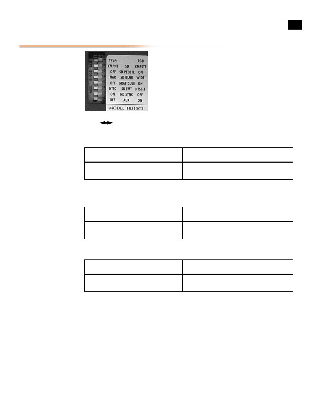
configure the DIP switch for the desired equipment configuration and video formats
3.
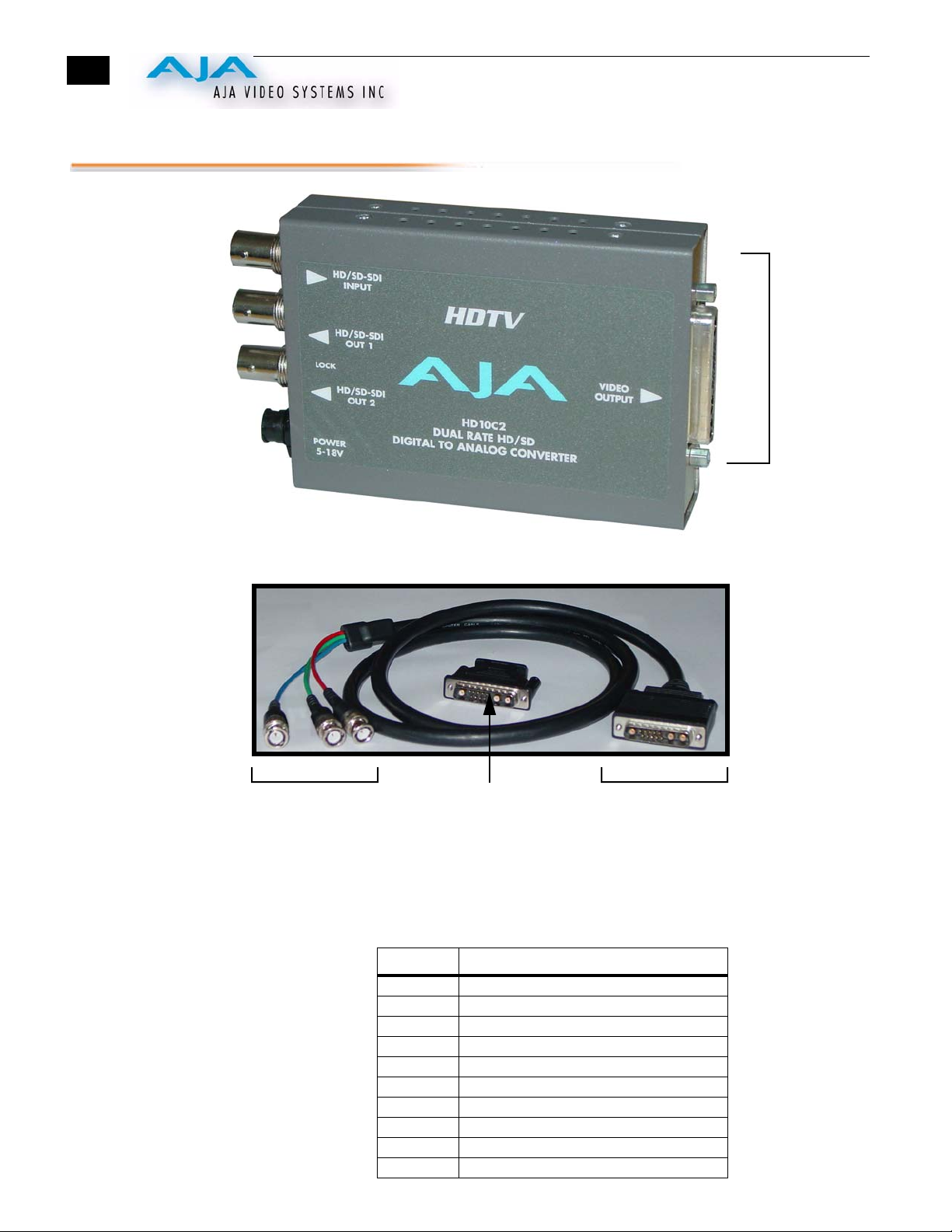
connect video equipment to the convertor BNCs
4.
apply +5 to +18VDC power to the converter (AJA power supply model DWP)
Specifications
Horizontal Scan
rates
1
Most VGA monitors are not compatible with an Horizontal scan rate below 30 Khz
(including the SONY GDM-W900, a popular HD monitor). The Sony 20L5 and 14L5 are
compatible with all formats supported on the HD10C2.
Item Specification
Formats 1080i @ 50/59.94/60 Hz
1080p sf @ 23.98/24/25/29.97/30 Hz (displayed as
interlaced)
1035i @ 59.94/60 Hz
720p @ 59.94/60 Hz
525i @ 59.94 Hz
625i @ 50 Hz
Input Selection Automatic
Video Input HD-SDI/SDI, SMPTE-259/292/296
Input Equalization 100/300 meter 1694 cable (SD/HD)
SDI Outputs HD-SDI/SDI, active input loop, Equalizing
Video Output: HD:YPbPr, RGB
SD: YPbPr, RGB (component mode)
Composite/YC (composite mode)
D/A converters: 12 bits
Sync Bi-level, Tri-level, H/V drive
2T K factor < 1% (Y)
Frequency Response Y +/ -.5db to 30 MHz
C +/- .25db to 15 MHz
Y/C delay < 2 ns
Power
(AJA power supply model DWP)
+5 to +18v DC regulated, 4 watt
Size 147 x 79 x 25 mm
Format H ScanRate
1080i 59.94 / 60 Hz 33.75 Khz
1080i 50 28.125 Khz
1
1080p sf 23.98 / 24 Hz 27.000 Khz
1
720p 59.94 / 60 Hz 45.000 Khz
Test Equipment Depot - 800.517.8431 - 99 Washington Street Melrose, MA 02176 - FAX 781.665.0780 - TestEquipmentDepot.com
Table of contents