TeST TST-14 Bonus M User manual

AIRCRAFT MANUAL
ADVANCED ULTRALIGHT AIRCRAFT
TST – 14 BONUS M
SERIAL NUMBER: 14010806
REGISTRATION:
Date of issue: 2006-11-29
Manufacturer: TeST, s. r. o.
Signature:
Registered copy Nr.
To ensure a safe flight, this aircraft must be operated according to the
information and limits published in this document !
PLEASE READ ALL INSTRUCTIONS CAREFULLY BEFORE OPERATING
THE AIRCRAFT !
TST-14 M – Aircraft Manual
rev.0 issued 2006-11-29 – page 1 of 40

LIST OF REVISIONS
Rev. Description (modification) Pages changed Date
0 basic issue --- 061129
TST-14 M – Aircraft Manual
rev.0 issued 2006-11-29 – page 2 of 40

LIST OF VALID PAGES
Page Nr. Date Page Nr. Date Page Nr. Date
1 2006-11-29 31 2006-11-29
2 2006-11-29 32 2006-11-29
3 2006-11-29 33 2006-11-29
4 2006-11-29 34 2006-11-29
5 2006-11-29 35 2006-11-29
6 2006-11-29 36 2006-11-29
7 2006-11-29 37 2006-11-29
8 2006-11-29 38 2006-11-29
9 2006-11-29
10 2006-11-29
11 2006-11-29
12 2006-11-29
13 2006-11-29
14 2006-11-29
15 2006-11-29
16 2006-11-29
17 2006-11-29
18 2006-11-29
19 2006-11-29
20 2006-11-29
21 2006-11-29
22 2006-11-29
23 2006-11-29
24 2006-11-29
25 2006-11-29
26 2006-11-29
27 2006-11-29
28 2006-11-29
29 2006-11-29
30 2006-11-29
TST-14 M – Aircraft Manual
rev.0 issued 2006-11-29 – page 3 of 40

CONTENTS1...........................................................................................................GENERAL
.......................................................................................................................................................................6
1.1 INTRODUCTION.......................................................................................................................................6
1.2 CERTIFICATION.......................................................................................................................................6
1.3 WARNINGS AND MISCELANEOUS......................................................................................................6
AIRCRAFT DESCRIPTION...............................................................................................................................7
2.1 WING.............................................................................................................................................................7
2.2 FUSELAGE.....................................................................................................................................................7
2.3 TAIL...............................................................................................................................................................7
2.4 CONTROLS.................................................................................................................................................7
2.5 UNDERCARRIAGE...................................................................................................................................7
2.6 PROPULSION GROUP..............................................................................................................................7
2.7 MINIMUM EQUIPMENT..........................................................................................................................8
2.8 DIMENSIONS .............................................................................................................................................8
2.9 FLIGHT CHARACTERISTICS..............................................................................................................10
2.10 THREE VIEW DIAGRAM...................................................................................................................12
3AIRCRAFT OPERATION INSTRUCTIONS OPERATIONAL LIMITS AND
INFORMATION...........................................................................................................................13
3.1 GENERAL .................................................................................................................................................13
3.2 SPEED LIMITATIONS............................................................................................................................13
3.3 AIRSPEED INDICATOR MARKINGS..................................................................................................14
3.4 ENGINE LIMITATIONS.........................................................................................................................14
3.5 WEIGHT LIMITATIONS........................................................................................................................14
3.6 CENTRE OF GRAVITY (CG).................................................................................................................15
3.7 PERMITTED MANEOUVRES ...............................................................................................................15
3.8 OPERATIONAL LIMIT ..........................................................................................................................15
3.9 WIND VELOCITY....................................................................................................................................16
3.10 SIGNS AND PLACARDS......................................................................................................................16
3.11 CONTROLS AND LEVERS IN COCKPITS ......................................................................................16
3.12 INSTRUMENT BOARD........................................................................................................................17
4AIRCRAFT OPERATION INSTRUCTIONS NORMAL PROCEDURES.......................18
4.1 GENERAL .................................................................................................................................................18
4.2 RIGGING AND DERIGGING OF THE AIRCRAFT............................................................................18
4.3 MANIPULATION ON GROUND............................................................................................................19
EXTENDING THE ENGINE ON THE GROUND ..........................................................................................19
4.5 PRE FLIGHT INSPECTION...................................................................................................................20
4.6 FUELLING AND ENGINE TEST ...........................................................................................................21
4.7 TAKE OFF.................................................................................................................................................21
4.8 FLIGHT......................................................................................................................................................23
4.9 APPROACH AND LANDING.................................................................................................................26
TST-14 M – Aircraft Manual
rev.0 issued 2006-11-29 – page 4 of 40

INSPECTION BETWEEN FLIGHTS...............................................................................................................26
4.11 POST FLIGHT INSPECTION .............................................................................................................27
4.12 REGULAR INSPECTION....................................................................................................................27
5AIRCRAFT OPERATION INSTRUCTIONS EMERGENCY PROCEDURES...........28
5.1 GENERAL .................................................................................................................................................28
5.2 STALL CHARACTERISTICS ................................................................................................................28
5.3 SPIRAL DIVE RECOVERY....................................................................................................................28
5.4 SPIN RECOVERY ....................................................................................................................................28
5.5 ENGINE FAILURE...................................................................................................................................29
5.6 ENGINE FIRE...........................................................................................................................................30
5.7 BAILING OUT OF THE AIRCRAFT.....................................................................................................30
5.8 USE OF AROCKET RESCUE SYSTEM (BRS)....................................................................................30
6MAINTENANCE AND INSPECTION PROCEDURE..........................................................................32
6.1 LIFETIME OF THE AIRFRAME...........................................................................................................32
6.2 REGULAR MAINTENANCE..................................................................................................................32
6.3 PERIODIC INSPECTION........................................................................................................................34
6.4 ADJUSTMENTS OF CONTROLS..........................................................................................................37
6.5 FIT OF WING MOUNTING BRACKETS .............................................................................................37
6.6 OPERATION AND MAINTENANCE....................................................................................................37
7DIRECTIONS FOR REPAIRS.................................................................................................................39
7.1 SUBSTITUTE MATERIALS...................................................................................................................39
7.2 GENERAL REPAIRS...............................................................................................................................39
8TRANSPORT IN THE TRAILER............................................................................................................40
9PARKING ...................................................................................................................................................40
TST-14 M – Aircraft Manual
rev.0 issued 2006-11-29 – page 5 of 40

1 GENERAL
1.1 INTRODUCTION
This manual contains the minimum required procedures that have to be followed in order for
the aircraft to be operated safely. The owner of the aircraft must comply with all regulations
that apply to this type of aircraft and flight rules generally valid for operation of aircraft in this
category.
1.2 CERTIFICATION
This aircraft conforms with the following ASTM standards:
ASTM 2564-06 Design and Performance of a Light Sport Glider
ASTM 2295-06 Continued Operational Safety Monitoring of a Light Sport Aircraft
ASTM 2279-06 Quality Assurance in the Manufacture of Fixed Wing Light Sport Aircraft
ASTM 2316-06 Airframe Emergency Parachutes for Light Sport Aircraft
1.3 WARNINGS AND MISCELANEOUS
Expressions such as WARNING, ATTENTION and NOTE, which appear in this document,
are defined as follows:
WARNING: Ignoring recommended procedures could create dangerous or hazardous
conditions in flight, which could cause serious injury or death.
ATTENTION: Ignoring recommended procedures could create dangerous or hazardous
conditions in flight and could compromise the safety of the flight..
NOTE: explains an item, which does not affect safety directly, but is important or unusual.
TST-14 M – Aircraft Manual
rev.0 issued 2006-11-29 – page 6 of 40

2 AIRCRAFT DESCRIPTION
The aircraft is a two-seat, high-winged monoplane with a cantilever wing, T-shaped tail and a
tandem two-wheel undercarriage. Its composite structure is made in negative moulds.
2.1 Wing
The wing consists of a sandwich structure equipped with ailerons and an air brake on the
upper surface. There are no ribs in the wing. The strength of the wing system is formed by
the main spar, the aileron spar and the root rib. The spar has a C-D shape including flanges
made of carbon composite. The complete wing profile of the sandwich structure forms the
torsion box. The wings are interconnected by fittings and two horizontal pins. The wing-
fuselage connection is made by means of pins and fittings placed in the fuselage and the
wing root rib. The composite ailerons are attached via four hinges with the axis of rotation on
the upper side. Air brakes on the upper side of the wing are made of aluminium and are
retracted into pits.
2.2 Fuselage
The fuselage is a shell structure made in a negative mould including the fin.
2.3 Tail
The tail is a T-shaped sandwich structure.
2.4 CONTROLS
Pitch, roll, air brake and trim are controlled via a lever design, with a push-pull rod system.
The control backstops are placed on the control stick. Yaw control includes adjustable pedals
and is transmitted by cables. The aircraft can be trimmed by a torsional member in the
elevator drive that is controlled by a lever in the left of the front cockpit.
2.5 UNDERCARRIAGE
The main landing gear with main wheel (350 x 100 mm) is housed in a swinging spring-
mounted fork. The front wheel is fixed. A lever located on the left hand side of the cockpit
floor controls the brake. The tail landing gear is provided with a turnable tail wheel (80 x 30
mm).
2.6 PROPULSION GROUP
The aircraft is driven by an auxiliary engine ROTAX 503UL-D.C.D.I cooled by the air stream.
with a1:2 type B reducer. The fixed wooden propeller has a diameter of 1200 mm and a pitch
TST-14 M – Aircraft Manual
rev.0 issued 2006-11-29 – page 7 of 40

of 850 mm. The engine bed is made of thin-wall steel profiles (material L-CM 3) , using four
rubber springs with a diameter of 60 mm. The bed rotates on a 15 mm diameter pin and
includes swivel bearings placed in brackets on the wing root spar fittings. The power plant is
extended by a 12 V DC servo with a epicyclic gear and trapezoidal self-locking screw with a
nut. The set is balanced by a gas strut. Both the servo and the struts act on the bed via a
common pin, with their reaction with the fuselage baffle being distributed through the
common pin and a support. The position of the main turning point, the angle of the extention
and small distance between the engine CG and the aircraft CG results in an insignificant
displacement of the CG between the extended and retracted power plant. The power plant is
locked in both end positions by backstops. The engine area is covered by doors controlled by
an independent servo.
The pilot controls extention and retracting of the power unit by two push buttons on the
instrument panel, one for extension, the other one for retracting. The movement is controlled
by an electronic unit controlled by a microprocessor, which takes care of an automatic
opening of the engine doors, end position voltage-out switches, signals informing the pilot
and connecting of the starter only in fully extended position. Also retraction of the engine
while the engine is running is not possible. The propeller is stopped in its vertical position for
retraction by an automatic backstop.
The fuel tank is from welded aluminium sheet placed in a sealed composite compartment in
front of the baffle Nr.5. Venting and drainage is through landing gear pit. Fuel is supplied to
the engine by a flexible hose through an interchangeable fuel filter, fuel cock and membrane
fuel pump into two floatless membrane carburettors. There is a fuel capacity sensor in the
tank. Refuelling is done by means of a funnel through a 25 mm hose with a filler cap on the
right side of the fuselage. Drainage is possible through the landing gear pit.. A manually
operated fuel priming pump is located on the instrument panel.
2.7 MINIMUM EQUIPMENT
The aircraft is required to have the following minimum equipment
2 AlfaMFD multifunction instruments
2 symmetrical safety belts
1 magnetic compass
1 review mirror
2.8 DIMENSIONS
2.8.1 Wing:
Span 17.00 m (55.8 ft)
Area 12.084 m2 (130.2 ft2)
Aspect ratio 23.92
Root chord 1.00 m (3.3 ft)
Tip chord 0.36 m (1.1 ft)
Angle of Attack +40
TST-14 M – Aircraft Manual
rev.0 issued 2006-11-29 – page 8 of 40

Dihedral +30
Geometrical Torsion 0
Airfoil Wortmann mod.
Aileron deflection +12o-24o
Dive brakes on the upper side 0.16 m2 (1.77 ft2)
2.8.2 Horizontal Tail:
Span 2.4 m (7.9 ft)
Area 1.07 m2 (11.5 ft)
Root chord 0.55 m (1.8 ft)
Tip chord 0.35 m (1.1 ft)
Elevator area 0.355 m2(3.82 ft2)
Arm of the horizontal tail 4.18 m (13.7 ft)
Deflection Up -20o
Deflection Down +16o
Airfoil NACA 0011
Angle of attack 0o
2.8.3 Vertical Tail:
Height 1.19 m (3.9 ft)
Root chord 0.99 m (3.2 ft)
Tip chord 0.65 m (2.1 ft)
Area 0.949 m2(10.2 ft2)
Rudder Area 0.294 m2(3.15 ft2)
Deflection +/- 35o
Airfoil E 474
2.8.4 Fuselage:
Length 8.24 m (27.1 ft)
Width 0.64 m (2.1 ft)
Height 1.1 m (3.6 ft)
Max. Cross Section 0.48 m2(4.9 ft2)
2.8.5 Engine:
Type Rotax 503 UL SCDI
two cylinders, two stroke, with type B reducer 1:2
Cooling Air cooled
Cylinder capacity 496.7 ccm (30.0 cu.in.)
Stroke 61 mm (2.40 in.)
Bore 72 mm (2.82 in.)
Performance 37 kW / 6500 rpm
TST-14 M – Aircraft Manual
rev.0 issued 2006-11-29 – page 9 of 40

Lubrication Fuel mixed with oil, 50 : 1
Starter electric
Weight 45.7 kg (101 lbs)
Carburetors 2x membrane (floatless) type
Battery 12V / 14 Ah
Fuel gasoline 95 octanes
Lubricant Castrol TTS or equivalent
For further details, see the Operator’s Manual of the engine.
2.8.6 Weights
Max. take-off weight 450 kg (992 lbs) or 472.5 kg (1042 lbs) with BRS
Empty weight 280 kg (617 lbs) or 300 kg (461 lbs) with BRS
Weight of pilots 70 – 180 kg (148 - 397 lbs)
2.9 FLIGHT CHARACTERISTICS
Stall Speed vSO 65 km/h [35.1 kt]
Max. design speed vD 228 km/h [123.1 kt]
Max. permissible Speed vNE 205 km/h [110.7 kt]
Max. aerotowing speed vT150 km/h [80.1 kt]
Max. gust speed vB150 km/h [80.1 kt]
Max. speed under power vC140 km/h [75,6 kt]
Max. glide ratio (theor.) 40.2 / 105 km/h [40.2 / 56.8 kt]
Operational loads +5.2 / -2.6 at vA= 150 km/h [81.0 kt]
+4/-2atv
NE = 205 km/h [110.7 kt]
TST-14 M – Aircraft Manual
rev.0 issued 2006-11-29 – page 10 of 40

Envelope of the aircraft TST-14
m=450kg
-4
-3
-2
-1
0
1
2
3
4
5
6
0 20 40 60 80 100 120 140 160 180 200 220 240
speed (km/h)
TST-14 M – Aircraft Manual
rev.0 issued 2006-11-29 – page 11 of 40

2.10 THREE VIEW DIAGRAM
5
TST-14 M – Aircraft Manual
rev.0 issued 2006-11-29 – page 12 of 40

3 AIRCRAFT OPERATION INSTRUCTIONS
OPERATIONAL LIMITS AND INFORMATION
3.1 GENERAL
This section provides limits for speed, mass, CG and other specifications that are necessary
for the safe operation of the aircraft.
WARNING: Ignoring any of the limits published below could result in damage to the aircraft
and /or personal injury or loss of life.
3.2 SPEED LIMITATIONS
3.2.1 VSO STALL SPEED 65 km/h [35.1 kt]
Stall speed in landing configuration as shown on the airspeed indicator to be corrected for the
instrument installation error.
WARNING: In flight, do not fly the aircraft less than 10 km/h (4 kt) above the stall speed.
3.2.2 VADESIGN SAFETY SPEED 150 km/h [81,0 kt]
WARNING: Full deflections of controls are not permitted at speeds above vA.
3.2.3 VBSPEED FOR MAX. GUST INTENSITY 150 km/h [81,0 kt]
This pertains to mechanical turbulence, gusts, and approaching thunderstorms.
WARNING: do not fly the aircraft over this speed limit in the above mentioned weather
conditions.
3.2.4 VCMAX. SPEED WITH RUNNING ENGINE 140 km/h [75.6 kt]
WARNING: do not fly the aircraft over this speed limit while the engine is running.
3.2.5 VNE NEVER EXCEED SPEED 205 km/h [110,7 kt]
WARNING: do not exceed the above speed limit in flight. When operating near this speed
limit do not use more than 30% deflection of control surfaces.
3.2.6 VT MAX. ALLOWED TOWING SPEED 150 km/h [81,0 kt]
WARNING: do not exceed the above speed limit while aerotowing. Verify (before beginning
aerotow), that the towing aircraft is able to tow safely at a speed lower than this maximum
speed.
TST-14 M – Aircraft Manual
rev.0 issued 2006-11-29 – page 13 of 40

3.3 AIRSPEED INDICATOR MARKINGS
WHITE BAND 65-80 km/h Speed from VSO up to min. cruising speed
GREEN BAND 80-150 km/h NORMAL cruising speed up to VBspeed
YELLOW BAND 150-205 km/h Flight can be executed in calm air only up to VNE
RED LINE 205 km/h NEVER EXCEED SPEED VNE
65 km/h STALL SPEED VSO
YELLOW TRIANGLE 100 km/h Landing approach speed with max. gross weight
WARNING: keep the marking visible and keep to the recommended speed limits
3.4 ENGINE LIMITATIONS
Engine: Rotax 503 UL SCDI
max. take-off performance 37 kW / 6 500 rpm
max. take-off rpm 6 500
max. cylinder head temperature 280oC
fuel gasoline 95 octanes, synthetic oil 1:50
fuel tank volume 12 litres [3.1 US gal]
usable fuel 11 litres [2.7 US gal]
3.5 WEIGHT LIMITATIONS
3.5.1 MAX. TAKE OFF WEIGHT 472,5 kg [1042 lbs]
Maximum weight at which the aircraft may be operated.
3.5.2 EMPTY WEIGHT 280 kg [617 lbs]
Maximum weight of the aircraft and equipment without pilot or passenger.
3.5.3 MAX. WEIGHT OF PILOTS 180 kg [397 lbs]
(including a parachute)
3.5.4 MAX. WEIGHT OF PILOT IN THE FRONT SEAT 100 kg [220 lbs]
(including a parachute)
3.5.5 MIN. WEIGHT OF PILOT IN THE FRONT SEAT 75 kg [ 165 lbs]
(including a parachute).
TST-14 M – Aircraft Manual
rev.0 issued 2006-11-29 – page 14 of 40

3.5.5.1 Additional ballast for a lighter pilot in the front cockpit
Pilot 75 kg and more no weight
Pilot 70-75 kg 1 weight ( 3 kg )
Pilot 65-70 kg 2 weights ( 6 kg )
Pilot 60-65 kg 3 weights ( 9 kg )
The sum of weights of pilots in both cockpits including the additional ballast in the front
cockpit : no more than 180 kg.
Maximum weight of the front pilot: 100 kg.
WARNING: Care must be excercised to ensure that the correct amount of additional ballast
is used. Install and secure the weights properly.
ATTENTION: do not overload the aircraft
WARNING: If only one pilot flies, the aircraft must be flown from the front seat. Ensure that
the minimum weight of the pilot including parachute is not below 75 kg. If the pilot is lighter,
add appropriate ballast under the pilot’s seat, or to the fixed ballast position if provided.
3.6 CENTRE OF GRAVITY (CG)
MAXIMUM FRONT 2775 mm from the datum line
MAXIMUM AFT 2858 mm from the datum line
Datum line is a vertical level perpendicular to the longitudinal axis of the aircraft, touching the
nose in the flight position. Pilot’s weight (70 – 100 kg) is included.
WARNING: Any modifications done on the aircraft, that can change the CG position, must
be consulted with the manufacturer.
3.7 PERMITTED MANEOUVRES
Steep turns with a maximum 45obank angle are permitted.
WARNING: Aerobatics, intentional falls and spins are prohibited !
At maneuvering, the following load factors cannot be exceeded:
up to vA = 150 km/h [81,0 kt] n = +5,3 and n = -2,6
at vNE = 205 km/h [110,7 kt] n = +4 and n = -2
3.8 OPERATIONAL LIMIT
The aircraft shall be operated according to VFR regulations during daylight hours only. Flight
in clouds or in icing conditions is prohibited.
TST-14 M – Aircraft Manual
rev.0 issued 2006-11-29 – page 15 of 40
3.9 WIND VELOCITY
Maximum wind speed parallel to the line of take off: 8 m/s [15.5 kt]
Maximum wind speed for 90ocrosswind: 4 m/s [7.8 kt]
ATTENTION: do not operate the aircraft if wind velocity exceeds the maximum permissible
speed.
3.10 SIGNS AND PLACARDS
3.10.1 OUTSIDE SIGNS
Left side of the fuselage in close proximity to the landing gear: TIRE 250 kPa [38 psi]
Trailing edges of the wings, ailerons and elevator: DO NOT PUSH
Trailing edge of the rudder on both sides: DO NOT PUSH
Pitot pressure tube: red color
3.10.2 INSIDE PLACARDS
On the instrument panel: weight information
On the instrument panel: speed information
Cockpit – right side: compass deviation table
Centre-section bulkhead: name plate
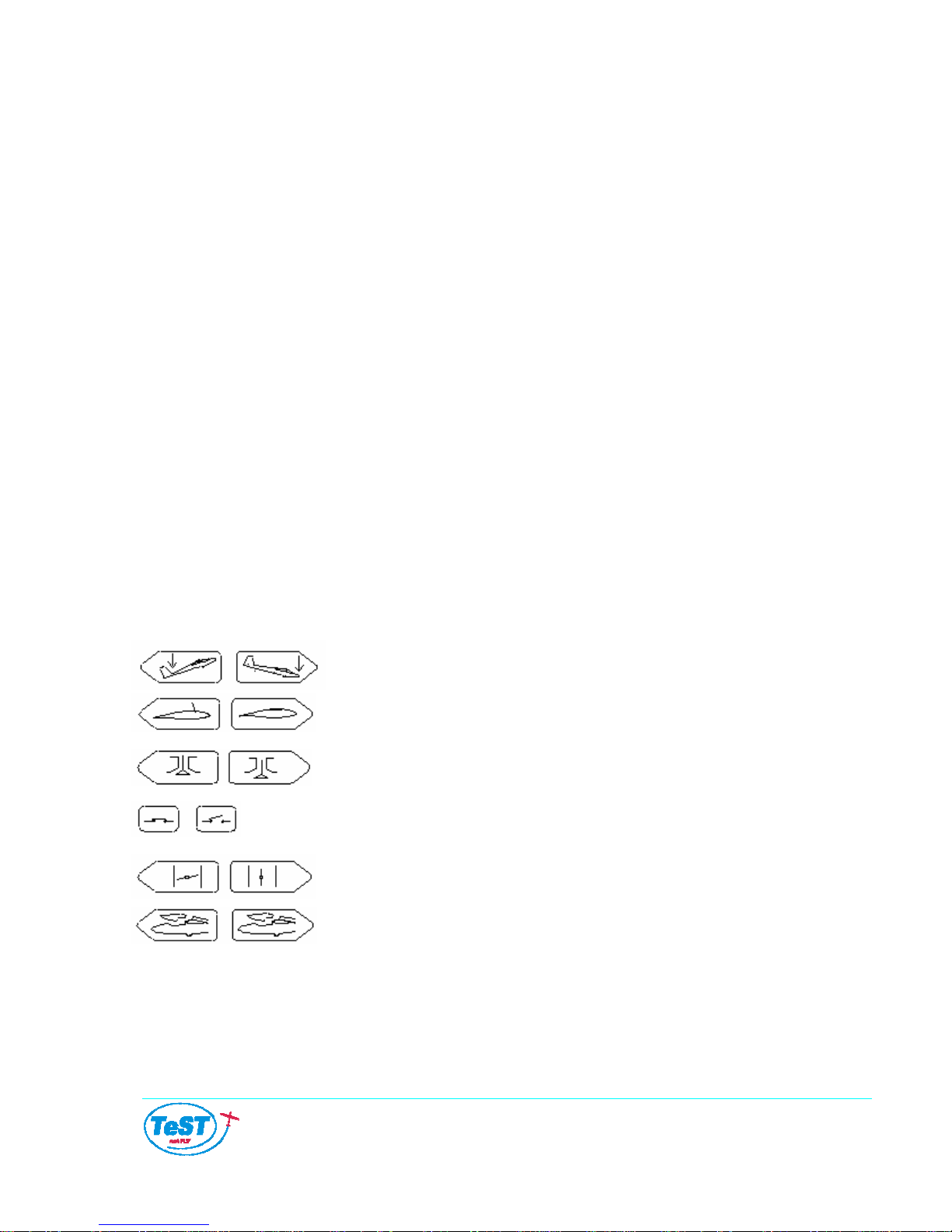
Symbols used:
Trim: heavy on tail – heavy on nose
Air brakes: extended – retracted
Fuel valve: closed – open
Main switch: ON – OFF
Throttle: idle – full
Canopy: open
3.11 CONTR ND
A. The control stick is of usual type with a hand grip.
OLS A LEVERS IN COCKPITS
B. The front rudder pedals are ground adjustable.
TST-14 M – Aircraft Manual
rev.0 issued 2006-11-29 – page 16 of 40

C. The lever for dive brakes control is located on the left side of the cockpit (blue color) and
the positions OPEN and CLOSE are placarded.
D. The trim control (green color) is on the left side of the front cockpit and NOSE HEAVY
and TAIL HEAVY positions are placarded.
E. The wheel brake is controlled by a lever (purple colour) on the left hand side of the
cockpit floor.
F. The canopy locks are located on the left and right side of the canopies.
G. The pull rod for the cockpit ventilation is placed on the right side below the front canopy
frame. The positions OPEN and CLOSED are placarded.
H. The throttle lever is located on the left side (when a power unit is installed).
I, The switches and push buttons for extending / retracting the power unit are located on
the instrument panel (see the following picture), if a power unit is installed.
3.12 INSTRUMENT BOARD
Legend:
1. Instrument panel AlphaMFD
2. Power indication lamp - green
3. Ignition switch
4. Main switch – starter
5. Radio (optional)
6. Fuel spraying pump PRIMER
7. Tow rope release
8. Engine retraction push button
9. ---
10.Engine extending push button
11.Bank indicator
12.Compass
NOTE: The instrument panel can vary depending on the individual requirements of the
customer. In such a case, see the attached photograph.
TST-14 M – Aircraft Manual
rev.0 issued 2006-11-29 – page 17 of 40

4 AIRCRAFT OPERATION INSTRUCTIONS
NORMAL PROCEDURES
4.1 GENERAL
ATTENTION: The recommended procedures described in this section are important. Be
sure to follow recommended speeds and all prescribed procedures and inspections.
4.2 RIGGING AND DERIGGING OF THE AIRCRAFT
The rigging and derigging of the aircraft should be done by three people. After finishing
assembly, check all control surfaces for correct direction of movement and movement
throughout the full range up to their stops.
4.2.1 Rigging of the wings
1. Using the inspection mode of the engine controls (see below paragraph 4.4) open the
engine doors and extend the engine
2. insert the left wing into the fuselage so that the fuselage pins match their counterparts in
the wing
3. insert the right wing into the fuselage so that the fuselage pins match their counterparts in
the wing
4. insert the main pins of the wings. Put on the pin covers and tighten them with the screws
in order to minimize the clearance between spars
5. secure all screws with a safety wire
6. connect the driving shafts of the ailerons and dive brakes with pins. Secure
them in their positions with nuts and cotter pin
7. inspect deflections of ailerons and dive brakes
8. switch over to automatic mode of engine control, and extend or retract the engine if
needed
NOTE: The wing pins are matching the openings of the fittings. To remove them, use a
knock-out jig.
4.2.2 Rigging of the horizontal tail
1. place the horizontal tail on the fin and move it backwards to insert its pins into the sleeves
in the fin
2. screw down the vertical bolt connecting the elevator to the rudder and secure it with a
safety wire
3. interconnect the control rod with the elevator lever and secure it
4. inspect the deflection of the elevator
TST-14 M – Aircraft Manual
rev.0 issued 2006-11-29 – page 18 of 40

WARNING: After each rigging of the aircraft recheck for correct connection and securing of
all pins and connections. It is strongly recommended this duplicate inspection should be
carried out by an independent and experienced person.
4.2.3 Derigging of the aircraft
Derigging of the aircraft is to be carried out in the reverse sequence of rigging.
4.3 MANIPULATION ON GROUND
The aircraft is equipped with a castering tail wheel that enables easy manipulation of the
aircraft on the ground. The aircraft can be pushed backwards as well as turned on the spot
without lifting the tail. Towing behind a car is possible using a 5 m long cable (connected to
the aerotow hook). Tow speed should not exceed a fast walking speed. An assistant is
required to keep the wing tip off the ground. The canopies must be closed.
Where an engine is installed, taxing under own power is possible. The pilot in the cockpit
controls the engine with an assistant holding the wing tip. On a good surface, taxing without
an assistant is also possible (wingtip wheels aid in keeping the desired heading).
ATTENTION: When closing the front canopy, it must be raised a little and then the strut is
pushed forward allowing the canopy to be lowered uner continuous support to the closed
position. If this procedure is ignored, the hinge will be damaged.
NOTE: The undercarriage and most of all the tail wheel are designed for usual operation on a
good surface. If the surface is not good, an assistant should lift the tail wheel or a suitable jig
should be used.
4.4 EXTENDING THE ENGINE ON THE GROUND
The inspection mode of the engine controls is used when manipulating the engine and the
engine doors during refuelling, inspections or repairs. The procedure is as follows:
1. Simultaneously push both buttons for engine retraction and erection.
2. Keep these buttons pushed and turn the main switch to position 1
3. Release both push buttons. Both pilot lamps flash.
In this mode the opening of the engine doors and the movement of the engine can be
controlled by activating and keeping the buttons pushed.
Basic automatic mode is reactivated by turning the main switch to the position 0.
NOTE: manipulation with the engine is possible only when the main switch (key) is in position
1. Switching-off this main switch (key) immediately after any manipulation of the engine (up
or down) has been finished is highly recommended (it provides an additional protection for
the actuator motor).
TST-14 M – Aircraft Manual
rev.0 issued 2006-11-29 – page 19 of 40

NOTE: if controls for engine extention are also installed in the rear instrument panel, the
switches on this panel must be in position ON. If they are in position OFF, controlling from the
front seat is not possible.
4.5 PRE FLIGHT INSPECTION
Before each flight inspect the aircraft for general condition, damage, incorrect fitting of parts
and equipment, dirt, ruptures, clearances and leaks.
WARNING: if any damage is found or if the condition of any part of the aircraft has been
found unsatisfactory do not operate the aircraft.
Recommended pre flight inspection procedure: open the canopy and extend the dive brakes.
Inspect the following:
1. Right side of the cockpit
2. Fuselage under the cockpit
3. Landing wheel from the right side
4. Leading edge and the bottom of the right wing
5. Inspection cup of the right wing-aileron control drive
6. Outer part of the right wing
7. Right aileron
8. Upper surface of the right wing and spoiler
9. Power-plant from the right side
10. Right side of the fuselage
11. Tail
12. Fairings of the tail section
13. Right side of the tail
14. Fin and rudder
15. Tail wheel
16. Left side of the stabilizer and elevator
17. Left side of the fuselage
18. Upper surface of the left wing and spoiler
19. Power plant from the left side
20. Aileron of the left wing
21. Outer part of the left wing
22. Leading edge and the bottom of the left wing
23. Landing wheel from the left side
24. Fuselage under the canopy on the left side
25. Both cockpits and their equipment
26. Instruments
27. Canopy
28. If the engine is installed, inspect all parts of the power unit
WARNING: do not operate the aircraft if any damage has occurred !
TST-14 M – Aircraft Manual
rev.0 issued 2006-11-29 – page 20 of 40
Table of contents


