Testec SI-9001 Use and care manual
MODIFIED CALIBRATION GUIDE FOR SI-9001/9002 (Offset):
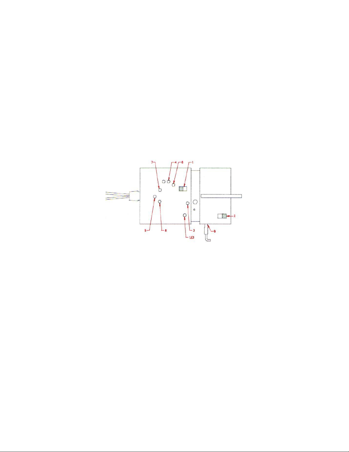
Explanation of adjustment point. Please refer to Fig. 7.
(1) SW1: Switch for selecting attenuation ratio.
(2) SW2: Power switch.
(3) VR4: Variable resistor for adjusting offset.
(4) VR2: Variable resistor for adjusting offset.
(5) VR1: Variable resistor for adjusting low frequency CMRR.
(6) VR3: Variable resistor for adjusting accuracy.
(7) VC1: Variable capacitor for adjusting square wave compensation.
(8) VC2: Variable capacitor for adjusting square wave compensation.
(9) CON1: Power jack for connecting to 6VDC power adapter
Adjustment Procedure:
Please connect a 6VDC power adaptor to CON1 as shown in the Figure above, and
turn “on” SW2, the LED indicator must light up. Keep the unit turned “on” for 10
minutes to keep it warm before the calibration starts. Then follow the steps below.
Offset Adjustment:
A. Referring to the Figure below, connect both input lines (black and red) together,
thus actually shorting the two input-leads. Make sure they are shorted to ensure that the
unit is calibrated properly. (Use an alligator clip for contact on the input lead, if
possible).
B. Connect BNC connector output to a DMM as shown in the Figure below. The
DMM should be properly set to mV range, better if the DMM have an auto-range
capability.
C. Put SW1 at 1/10 (or 1/20) attenuation setting as indicated at the front plastic
cover of the probe.
D. By referring to the Figure above, adjust VR2 using a ceramic screw or any tools
appropriate for adjusting variable component to make the output voltage approach to
zero. (This way the Offset is adjusted into range within 0.1mV).
E. Put SW1 at 1/100
(
or 1/200
)
attenuation settin
g
as indicated a
g
ain at the front

plastic cover of the probe.
F. Again referring to the Figure above, adjust VR4 to make output voltage approach
to zero. (This way the Offset is adjusted into range within 0.1mV). However, when VR4
is changed, the Offset at 1/10 is affected, thus we must calibrate again the 1/10 by
repeating steps C and D.
G. Again adjust the Offset at 1/100 by repeating steps E and F. Through this
continual repetition, we are minimizing the Offset for both SW1 settings until the Offset
for both attenuation (1/10 and 1/100) is set to the ideal zero or within range of 0.1mV.

Calibration of TT-SI 9001 & 9002
1. How to open the case, please follow the steps.
1.1 Remove the battery lid.
1.2 You will see the two screws and loosen them.
Fig. 1
1.3 Near the BNC cable side, there are two protuberant mortises. Use fingers to push back and pull
upward.
Fig. 2
1.4 Use fingers to press the bottom case inward, and pull it backward and upward.
Fig.3
1

1.5 Hold the bottom case and push back (to input lines direction).
Fig.4
1.6 You will see the two metal cases. There is one screw on the PCB. Loosen it, then the whole metal case
can be taken out. There are two wires still connected with the upper case. Leaves them there.
Fig. 5
1.7 The metal case is illustrated as follows:
Fig. 6
2

CALIBRATION GUIDE FOR SI-9001 / SI-9002 (Offset):
Explanation of adjustment point. Please refer to Fig. 7.
(1) SW1: Switch for selecting attenuation ratio.
(2) SW2: Power switch.
(3) VR4: Variable resistor for adjusting offset.
(4) VR2: Variable resistor for adjusting offset.
(5) VR1: Variable resistor for adjusting low frequency CMRR.
(6) VR3: Variable resistor for adjusting accuracy.
(7) VC1: Variable capacitor for adjusting square wave compensation.
(8) VC2: Variable capacitor for adjusting square wave compensation.
(9) CON1: Power jack for connecting to 6VDC power adapter
Fig. 7
Adjustment Procedure:
Please connect a 6VDC power adaptor to CON1 as shown in the Figure above, and
turn “on” SW2, the LED indicator must light up. Keep the unit turned “on” for 10
minutes to keep it warm before the calibration starts. Then follow the steps below.
Offset Adjustment:
A. Referring to the Figure below, connect both input lines (black and red) together,
thus actually shorting the two input-leads. Make sure they are shorted to ensure that the
unit is calibrated properly. (Use an alligator clip for contact on the input lead, if
possible).
B. Connect BNC connector output to a DMM as shown in the Figure below. The
DMM should be properly set to mV range, better if the DMM have an auto-range
capability.
C. Put SW1 at 1/10 (or 1/20) attenuation setting as indicated at the front plastic
cover of the probe.
3

D. By referring to the Figure above, adjust VR2 using a ceramic screw or any tools
appropriate for adjusting variable component to make the output voltage approach to
zero. (This way the Offset is adjusted into range within 0.1mV).
E. Put SW1 at 1/100 (or 1/200) attenuation setting as indicated again at the front
plastic cover of the probe.
F. Again referring to the Figure above, adjust VR4 to make output voltage approach
to zero. (This way the Offset is adjusted into range within 0.1mV). However, when VR4
is changed, the Offset at 1/10 is affected, thus we must calibrate again the 1/10 by
repeating steps C and D.
G. Again adjust the Offset at 1/100 by repeating steps E and F. Through this
continual repetition, we are minimizing the Offset for both SW1 settings until the Offset
for both attenuation (1/10 and 1/100) is set to the ideal zero or within range of 0.1mV.
Fig. 8
4

1.8 Low Frequency CMRR Adjustment
a. Referring to Fig. 9, connect output BNC to the oscilloscope which has good grounding.
b. Connect both input lines to a 220/200VAC, 60/50Hz power source.
c. Put SW1 at 1/10 (or 1/20).
d. Set the VOLTS/DIV switch on oscilloscope’s panel to 1mV and the TIME/DIV switch to 5ms. Then
a 60/50Hz sinusoid waveform should be displayed on the screen.
e. Adjust VR1 to make the amplitude of displayed waveform as small as possible. Finally the
amplitude should be less than 1.5mV.
Fig. 9
5

1.9 Square Wave Adjustment
a. Referring to Fig. 10, connect output BNC to the oscilloscope has good grounding.
b. Connect the red input line to a 20Vp-p, 10KHz square wave signal source and the black input line to
ground.
c. Put SW1 at 1/10 (or 1/20).
d. Set the VOLTS/DIV switch on oscilloscope’s panel to o.1V for 1/10 (or 1/20) attenuation and the
TIME/DIV switch to 20us.
e. Adjust VC1 to make the displayed waveform become as Fig 11(b).
f. Connect the black input line to 20Vp-p, 10KHz square wave signal source and the red input line to
ground.
g. Adjust VC2 to make the displayed waveform become as Fig. 11(b).
Fig. 10
6

Fig. 11
1.10 Repeat 3.2 and 3.3 adjustment until both adjustments are O.K.
1.11 High Frequency CMRR adjustment
a. Referring to Fig. 12, connect output BNC to the oscilloscope has good grounding.
b. Connect both input lines to a 155Vp-p, 20KHz, sine wave signal source.
c. Put SW1 at 1/10 (1/20).
d. Set VOLTS/DIV switch on oscilloscope’s panel to 1mV and the TIME/DIV switch to 0.1ms.
e. Adjust VC1 slightly to make the amplitude of displayed waveform as small as possible. Finally the
amplitude should be less than 2mV.
7

Fig. 12
1.12 Accuracy Adjustment
a. Referring to Fig. 13, connect output BNC to a DMM.
b. Connect the red input line to the positive terminal of a DC voltage source (70VDC) and the black
input line to the negative terminal source (70VDC).
c. Put SW1 at 1/10 (or 1/20).
8

d. Adjust VR3 to make the output voltage equal to 6.9V (or 3.51V for 1/20).
Fig. 13
9
This manual suits for next models
3
Other Testec Measuring Instrument manuals

Testec
Testec TT-SX 200 User manual

Testec
Testec TT-HVP 2739 User manual

Testec
Testec TT-SX 9001 User manual

Testec
Testec TT-HVP 15HF User manual

Testec
Testec TT-CC series User manual

Testec
Testec TT-SI 9101 User manual

Testec
Testec TT-SI 9001 User manual

Testec
Testec TT-AF 1200 User manual

Testec
Testec TT-SI 9010 User manual

Testec
Testec TT-SI 9010A User manual


