Testifire 2000 Series User manual

USER MANUAL
2000 SERIES
www.detectortesters.com/testire

www.detectortesters.com/testire
IMPORTANT INFORMATION
THE FOLLOWING SYMBOLS ARE USED THROUGHOUT
THIS USER MANUAL AND ON THE PRODUCT:
This symbol on the product indicates that there is a
safety hazard or an operation requiring care to avoid
damage to the product or environment. You must
read the appropriate sections of the User Manual to
understand the nature and severity of all the potential
hazards present and the action you must take.
This symbol on the product indicates that you should
read and understand this User Manual before using this
product.
This symbol on the product warns you of hot
surfaces or heat by convection.
This symbol on the product indicates that this part of
the device is susceptible to static damage.
To comply with WEEE (Waste Electrical & Electronic
Equipment) Regulations the crossed out refuse contain-
er symbol on this product or literature indicates that it
should not be disposed with other business waste at
the end of its working life. To help ensure that valuable
resources are reused and recycled, and to prevent
possible harm to the environment or human health
from uncontrolled waste disposal, please separate this
from any other types of waste.
THIS PRODUCT IS INTENDED TO BE USED AT HEIGHT.
EXERCISE GREAT CARE AND ALWAYS WEAR APPROPRIATE
PPE (PERSONAL PROTECTIVE EQUIPMENT) WHEN
OPERATING ABOVE HEAD HEIGHT IN ORDER TO AVOID
THE RISK OF INJURY.
• DO NOT OVER REACH. Keep proper footing and balance at
all times. Proper footing and balance enables better control of
the equipment in unexpected situations.
• Pay particular attention to avoid contact with overhead items
such as light ttings, overhead power cables and any other
objects that could be accidentally dislodged which might cause
danger to the operator or anyone else in the vicinity.
THIS PRODUCT CONTAINS HOT PARTS.
• DO NOT TOUCH the heat element. It may be very hot
immediately after use and may burn if touched.
This product emits small amounts of carbon monoxide (CO) gas
which is a harmful, odourless gas.
DO NOT INHALE directly from the duct during a CO test or within
5 minutes of conducting a CO test.
• DO NOT TOUCH the tip of the CO capsule when it has been
removed if the unit has been in operation within the previous 5
minutes. It will be very hot immediately after use and may burn
if touched.
• DO NOT insert ngers into the aperture from where the CO
capsule has been removed. There are very hot surfaces which
may burn if touched.
CAUTION
WARNING WARNING
WARNING
2
• This product is designed for indoor use only and should not be
subject to, or used in, a wet environment.
• To protect the high-precision technology contained in Testire,
never leave Testire in the places listed below, whether if in use
or in storage:
◦Places where temperatures and/or humidity are high or go
through extreme changes. Direct sunlight, or near other
heat sources (stoves, radiators, etc.) Always observe the
operating and storage environment restrictions detailed in
the Technical Specications
◦In sandy or dusty environments.
◦In places prone to strong vibration.
◦Near to sources of static or radio waves.
◦ Wet or moist environments. Testire is designed for indoor
use only
• Stop using Testire immediately if you notice any unusual
odours; liquids or noise coming from it. Switch off immediately
and consult technical support.
• Testire is not designed for use in hazardous areas (those con-
taining explosive vapour or dust).
• The Battery Baton should be removed when Testire is not in
use. This will prevent the gradual discharge of the battery and
prevent possible accidental operation of the head unit.
• Do not use your Testire if it is not operating properly. Consult
the Troubleshooting section of this manual and if required seek
technical advice.
• If the equipment is used in a manner not specied by the
manufacturer, the protection provided by the equipment may
be impaired.
• Use only approved accessories that are recommended by the
manufacturer for your Testire model.
• Always disconnect the battery from the charger once fully
charged. Leaving it connected, particularly when using a vehicle
power supply can lead to overheating and damage to the
battery.
• Take care when handling and storing your Testire. Dropping
on to a hard surface could damage it.
• If your Testire unit becomes damaged do not use it. Switch off
immediately and consult technical support.
READ THIS USER MANUAL COMPLETELY BEFORE USING YOUR TESTIFIRE.
SAVE THIS USER MANUAL - SAVE ALL SAFETY AND OPERATIONAL INSTRUCTIONS FOR FUTURE REFERENCE. TAKE
NOTE OF THE WARNINGS - READ CAREFULLY AND FOLLOW ALL WARNING LABELS ON THE PRODUCT AND THOSE
DESCRIBED IN THIS USER MANUAL.
NOTE: UNDER NORMAL OPERATING CONDITIONS,
THIS EMISSION WILL PRESENT NO HARM TO THE USER.
FOR ADDITIONAL INFORMATION PLEASE REFER TO THE
SEPARATE SAFETY INFORMATION PROVIDED.

www.detectortesters.com/testire 3
1 GENERAL INSTRUCTIONS 4
1.1 WARRANTY
1.2 ACKNOWLEDGEMENT
1.3 RECYCLING
1.4 CE DECLARATION
1.5 CARE OF YOUR TESTIFIRE
1.6 GENERAL CARE
2 TESTIFIRE 2000 SERIES INTRODUCTION 5
KIT CONTENTS 6
3 PREPARATION FOR USE 8
3.1 CHARGING THE BATTERY
3.2 INSERTING THE BATTERY
3.3 INSERTING THE SMOKE CAPSULE 9
3.4 INSERTING THE CO CAPSULE
4 GETTING STARTED 10
4.1 POWERING ON TESTIFIRE
4.2 INTERFACE & MAIN MENU 11
4.3 ADJUSTING HEAD UNIT ANGLE 12
4.4 TESTING HIGH PROFILE DETECTORS
5 SINGLE TEST 13
5.1 DEFAULT SMOKE TEST
5.2 HEAT TESTING 14
5.3 CO TESTING 15
5.4 CLEARING A DETECTOR
6 SEQUENTIAL TESTING 16
6.1 SMOKE TEST + CLEARING
6.2 SMOKE TEST + HEAT TEST 18
6.3 SMOKE TEST + CLEAR + HEAT TEST 20
6.4 SMOKE + CLEAR + HEAT + CO TEST 22
7 SIMULTANEOUS TESTING 24
7.1 SMOKE/HEAT
8 TESTIFRE INFRARED REMOTE CONTROL 25
9 SETTINGS 26
10 REMOVING & REPLACING CONSUMABLES 28
10.1 REMOVING THE SMOKE CAPSULE
10.2 REPLACING THE SMOKE CAPSULE
10.3 REMOVING THE CO CAPSULE 29
10.4 REPLACING THE CO CAPSULE
10.5 REMOVING THE BATTERY 30
10.6 REPLACING THE BATTERY
11 REMOVING & REPLACING SPARES 31
11.1 REMOVING THE CLEAR CUP
11.2 REPLACING THE CLEAR CUP
11.3 REMOVING THE MEMBRANE
11.4 REPLACING THE MEMBRANE
12 CONSUMABLES & ACCESSORIES 32
13 TECHNICAL SPECIFICATIONS 33
14 TROUBLESHOOTING & SUPPORT 34
14.1 IDENTIFYING ERRORS
14.2 GENERAL CARE
14.3 BATTERIES & CHARGERS
CONTENTS
4
1
www.detectortesters.com/testire
GENERAL INSTRUCTIONS
In addition to any other express warranty given in writing by the
Company in relation to the Goods, the Company warrants that
the Goods supplied under these terms and conditions will be in
accordance with the specication (if any) contained in the Purchase
Order, and will be free from defects in workmanship and material for
a period of 18 months from the date of delivery to the Buyer or for
a period of 12 months after the date of sale by the Buyer to the nal
customer whichever period is the shorter.
This product and its associated components are designed and
manufactured to be fully compliant with the requirements of the
following EU Directives for CE marking:
• EMC Directive 2014/30/EU of the European Parliament and
of the Council of 26 February 2014 on the
harmonisation of the laws of the Member States
relating to electromagnetic compatibility (recast).
• Low Voltage Directive 2014/35/EU of the European
Parliament and of the Council of 12 December 2006 on the
harmonisation of the laws of Member States relating to electrical
equipment designed for use within certain voltage limits.
• RoHS Directive 2011/65/EU of the European
Parliament and of the Council of 8 June 2011 on the restriction of
the use of certain hazardous substances in electrical and electronic
equipment.
• BAWBA Directive 2006/66/EC of the European Parliament and of
the Council of 6 September 2006 on batteries and accumulators
and waste batteries and accumulators and repealing Directive
91/157/EEC.
Testire®, Solo™ and Battery Baton™ are registered marks of
No Climb Products Ltd. All other brand names mentioned are
trademarks or registered marks of their respective holders, and
are hereby acknowledged.
©2017 No Climb Products Ltd. All Rights Reserved.
DO NOT DROP OR EXPOSE TESTIFIRE TO WATER.
Always store Testire, batteries and chargers in a suitable bag when
not in use.
Do not use Testire or Solo poles if they are damaged in any way.
The packaging can be easily separated into the following materials:
• Cardboard (outer box)
• Cardboard (inner buffers, boxes)
• Polyethylene (capsule bags)
• Plastic (capsule caps)
Please dispose in line with local environmental requirements.
WEEE (WASTE ELECTRICAL & ELECTRONIC
EQUIPMENT) REGULATIONS
Testire and Testire capsules are suitably marked to be recycled in
accordance with your local environmental requirements.
Alternatively these items may be returned to the manufacturer via
your reseller for disposal in compliance with WEEE (Waste Electrical
& Electronic Equipment) Regulations.
1.1 WARRANTY 1.5 CARE OF YOUR TESTIFIRE
1.6 GENERAL CARE
1.4 CE DECLARATION
1.2 ACKNOWLEDGEMENT
1.3 RECYCLING
• Only use genuine, specied batteries with your testire.
• Do not get dirt, sand, liquids, or other foreign matter on the
terminals.
• Do not touch the terminals with metal objects.
• Do not cover the battery or charger when in use.
• Do not place charging battery in or near a heat source
• Always disconnect the battery from the charger as soon as it
is fully charged, especially if the power could be repeatedly
disrupted e.g. when using in-vehicle power. Leaving the battery
connected may lead to overheating and damage to the battery.
• Solo 727 chargers will only work with Solo 770 battery batons.
They will not charge Solo 760 batteries.
NOTE: DIRT THAT GETS INTO THE CUP COULD GET
INTO THE UNIT THROUGH THE SMOKE/HEAT/CO DUCT
OPENING AND CAUSE THE UNIT TO FAIL. ALWAYS KEEP
THE CUP CLEAN TO ENSURE RELIABLE OPERATION.
SOLO 727 CHARGER SOLO 770 BATTERY
SOLO 726 CHARGER SOLO 760 BATTERY

USER INTERFACE KEYPAD
5
www.detectortesters.com/testire
TESTIFIRE 2000 SERIES
INTRODUCTION
2
Thank you for purchasing the Testire Multi-Sensor Detector Tester
This manual is designed to assist you to get the best and most efcient use of the Testire 2000 series and provides
all the information required to perform routine service and maintenance tasks with ease.
Testire includes advanced technology that simplies functional testing of smoke & heat detectors.
1. Bellows
2. Infrared Beam
3. Inner Clear Cup
4. Clear Cup
5. Main Duct for Heat
6. Smoke Capsule Cover
7. Test LED
8. Status LED
9. User Interface Display
10. CO Capsule Cover
11. Infrared Remote Control Receivers
12. Adjustable Handle
1. Menu
2. Status
3. Navigation
4. Enter/Conrm
5. On/Off
6. Return/Escape
1
2
3
5
4
7
11
9
11
12
6
10
8
1
3
5
2
4
6
6www.detectortesters.com/testire
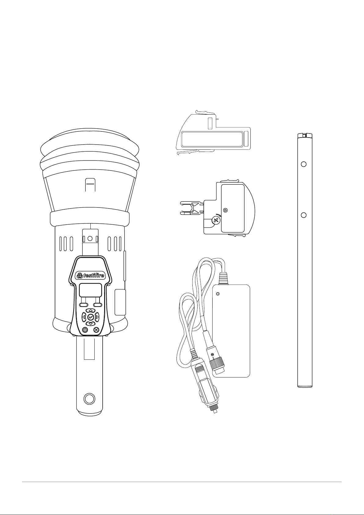
KIT CONTENTS
TESTIFIRE 2001-1 SMOKE, HEAT
& CO KIT CONTAINING:
1x TS3 SMOKE CAPSULE
1x TC3 CO CAPSULE
1x SOLO 727 CHARGER
1x SOLO 770 BATTERY
1x TESTIFIRE 2000 HEAD UNIT
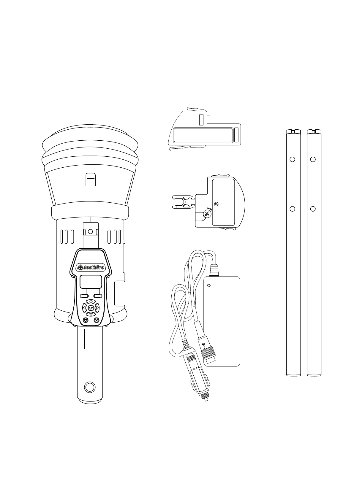
TESTIFIRE 2001 SMOKE, HEAT
& CO KIT CONTAINING:
7
www.detectortesters.com/testire
1x TC3 CO CAPSULE
1x TS3 SMOKE CAPSULE
1x SOLO 727 CHARGER
2x SOLO 770 BATTERY
1x TESTIFIRE 2000 HEAD UNIT

8
3
www.detectortesters.com/testire
PREPARATION FOR USE
Solo NiMH Battery Batons are used to power Testire and enable it
to be tted to Solo Access Poles.
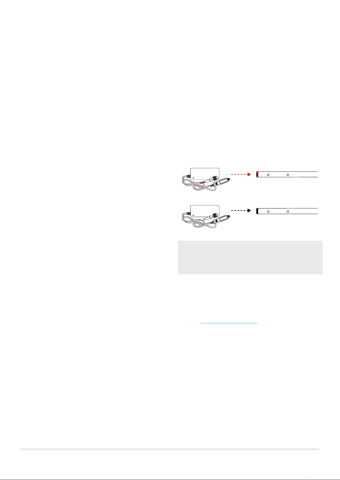
1. Connect charger to power outlet / vehicle accessory socket
using power cable supplied / umbilical DC connecting lead
respectively. LED will not illuminate permanently.
2. Connect the Battery Baton to the charger via the seven pin
polarised connector and turn the locking ring. (Fig. 1)
3. LED will ash red/green for approx 5 minutes, then illuminate
red only to indicate fast charging. LED illuminates green only
when battery is fully charged.
4. Charging times will depend on the discharge state of the Battery
Baton. Charge times can be 75-90 minutes when charging a
fully discharged Battery Baton.
5. Disconnect battery from the charger once fully charged to
prevent overheating and damage to the battery.
3.1 CHARGING THE BATTERY 3.2 INSERTING THE BATTERY
1. Hold the Testire head unit by the handle and press the upper
spring button on the Battery Baton. Align the button with the
location hole in the handle and push the Battery Baton into the
handle until the button springs up through the hole. (Fig. 2)
2. Insert the other end of the Battery Baton into the Solo access
pole and press the lower spring button. Align it with the
location hole and push the Battery Baton further into the pole
until the button springs up through the hole.
DO NOT ATTEMPT TO USE OR CHARGE THE BATTERY
IF EITHER THE UNIT OR THE BATTERY CONNECTION
POINT ARE DAMAGED. NEVER CONNECT AC AND DC
POWER AT THE SAME TIME.
WARNING
ENSURE CORRECT ORIENTATION WHEN INSERTING
THE BATTERY BATON INTO TESTIFIRE. DO NOT USE
UNDUE FORCE TO INSERT. REMOVE BATTERY FROM
TESTIFIRE WHEN NOT IN USE.
CAUTION
FIGURE 2
ALWAYS DISCONNECT THE BATTERY FROM THE
CHARGER AS SOON AS IT IS FULLY CHARGED, ES-
PECIALLY IF THE POWER COULD BE REPEATEDLY
DISRUPTED E.G. WHEN USING IN-VEHICLE POWER.
LEAVING THE BATTERY CONNECTED MAY LEAD TO
OVERHEATING AND DAMAGE TO THE BATTERY.
WARNING
FIGURE 1
The Solo 770 Battery Baton must be charged using a Solo charger
before using Testire. To ensure maximum duration of testing, it
should be fully charged for each use. A Solo 727 charger will fully
charge a Solo 770 battery in 60-90 minutes

9
3.3 INSERTING THE SMOKE CAPSULE
3.4 INSERTING THE CO CAPSULE
• DO NOT TOUCH THE CONTACTS ON THE PCB
ON THE CAPSULE. STATIC ELECTRICITY MAY
DAMAGE THEM AND CONTAMINATION OF THE
CONTACTS MUST BE AVOIDED.
• ALLOW THE CO CAPSULE TO COOL DOWN
BEFORE REMOVING
CAUTION
www.detectortesters.com/testire
1
Remove the spring clip protector
cap from the capsule.
1
Remove the tip protector cap
from the capsule.
2
Holding the capsule by the spring clips
with the label on the underside, insert the
capsule. Ensure that the clips spring out
positively on both sides of the capsule to
engage correctly with the port.
2
Holding the capsule by the spring clips
with the label facing upwards, insert the
capsule. Ensure that the clips spring out
positively on both sides of the capsule to
engage correctly with the port.
3
Close the access cover securely.
3
Close the access cover securely.
NOTE
Smoke & CO Capsules are non-rellable.
Only replace with genuine Testire TS3
Smoke Capsules & TC3 CO Capsules. It
is recommended the capsule should be
removed from the unit when not in use
for a few days.
10 www.detectortesters.com/testire
4GETTING STARTED
1
Press and hold the red power button
for 2 seconds.
4.1 POWERING ON TESTIFIRE
English
Deutsch
Español
Français
2
The rst time the unit is powered-on
you will be prompted to select the
Testire operating language for your
region. Use the up and down arrow
keys to navigate and enter key to
select your required operating language
3
This will display a conrmation screen.
Press the menu key to select or
the status’ key to cancel. Once the
language has been selected the main
menu will be displayed.
English
Select Cancel
NOTE
If the unit is left in Standby mode for
more than 5 minutes, it will power off to
conserve the battery.
NOTE
If not used within 16 days or when a
Smoke Capsule has been replaced, Testire
will self-prime at power-on, prior to
displaying the main menu. This is Indicated
by a message ‘Preparing for use’

11
www.detectortesters.com/testire
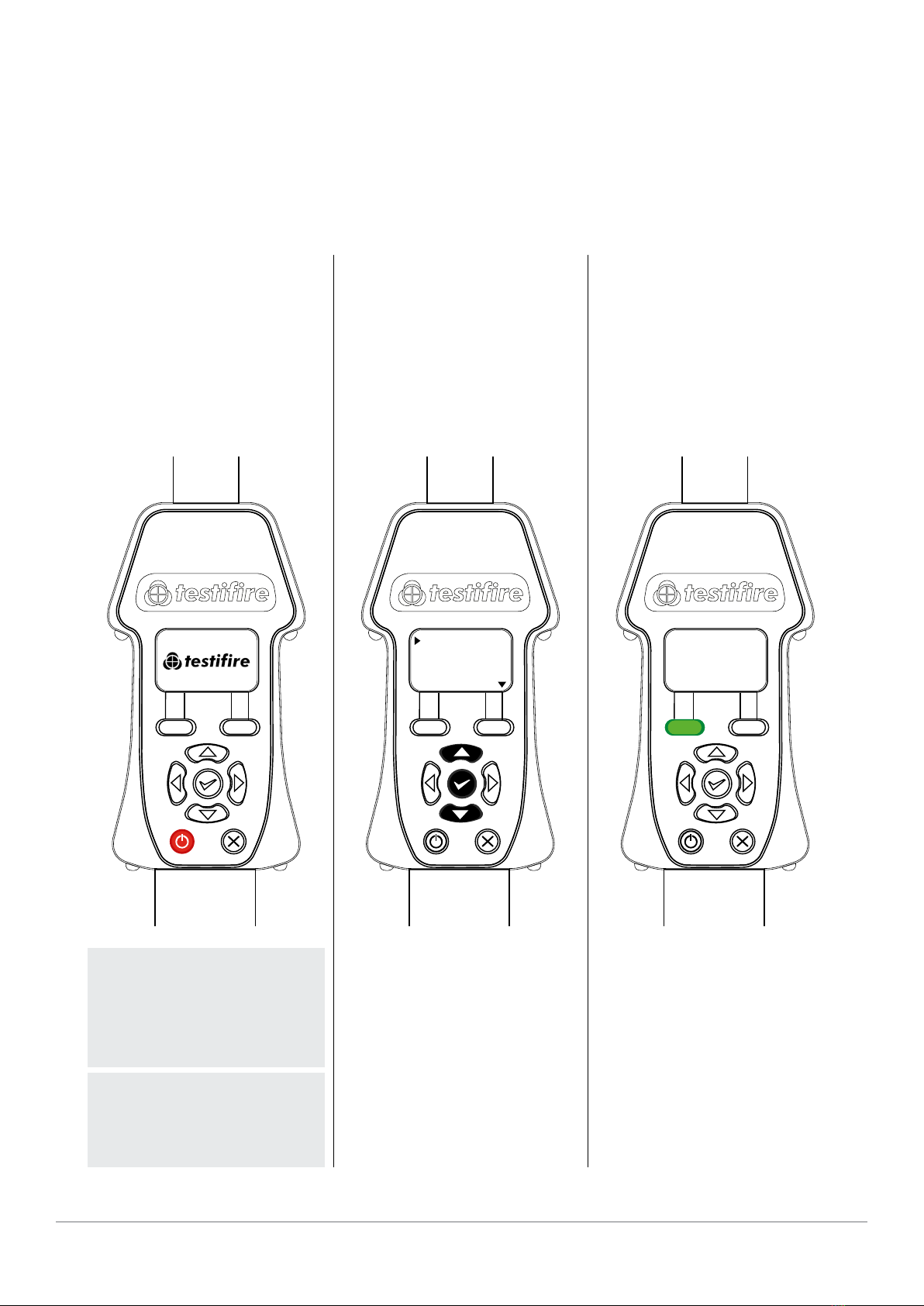
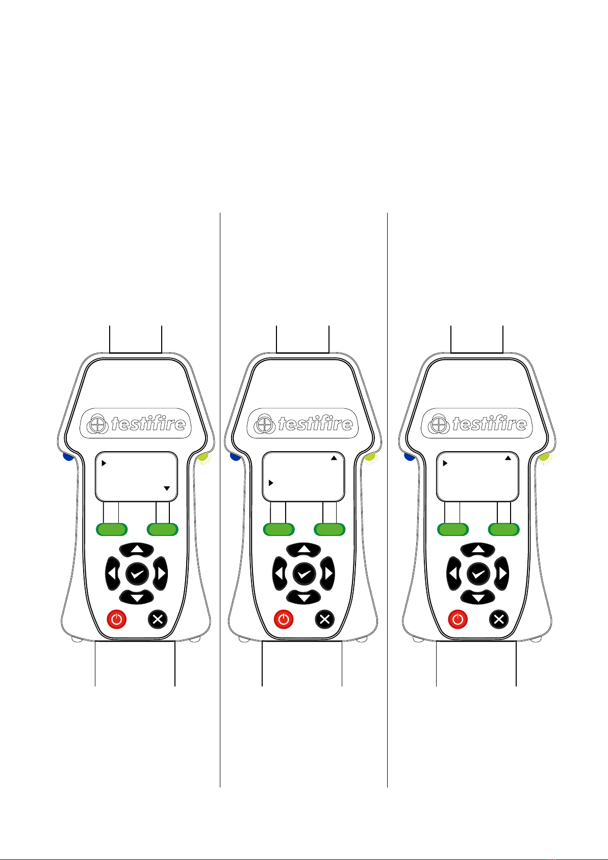
4.2 INTERFACE & MAIN MENU
TEST LED
MENU KEY
POWER BUTTON
ENTER KEY
Smoke
Heat
CO
Menu Status
Illuminates in the
colour of chosen
test. If multiple tests
are selected the LED
will ash alternately
with the colours of
selected tests
Display settings
On/Off
Navigate up and down through
the menus
Select
STATUS LED
MAIN MENU
NAVIGATION KEYS
Flashes slow green in idle mode.
Flashes fast green when a test is activated.
Turns red if an error has occured
STATUS KEY
ESCAPE KEY
Check Capsule level when Smoke is
selected. Display Heat status including
Hi-heat & timer options when
Heat is selected
Cancel selection or return to menu
Blue = Smoke Flashing Slow Green =
Idle Mode
Red = Heat
Green = CO
Flashing Fast Green =
Operational Mode
Double Flashing Green =
CO Element Cooling
Flashing Blue/Red/Green =
Smoke/Heat/CO simultaneous test
Solid Blue/Red & Green Alternating =
Smoke in progress, Heat/CO sequential test
Flashing Green/Red =
Testire TimeOut
Solid Red = Error
Clear = Clearing
Flashing Red =
Battery requires charging
TEST LED STATUS LED
LED REFERENCE CHART
|
|
|
|
|
|
|
|
|
|
|
|
|
|
|
|
|
|
|
|
|
|
|
|
|
|
|
|
|
|
|
|
|
|
|
|
|
|
|
|
|
|
|
|
|
|
|
|
|
|
|
|
|
|
|
|
|
|
|
|
|
|
|
|
|
|
|
|
|
|

12 www.detectortesters.com/testire
Correct head angle adjustment is important to make sure that the detector to be
tested is correctly positioned in the inner clear cup and the user is in a safe and
appropriate position to carry out the test.
The detector should touch the base of the Testire inner clear cup and should be
level with the base of the detector.
Adjust the head unit for the correct angle to access the detector.. Hold the body
of Testire and gently pull the handle away from the head unit.
The head unit will be free to rotate to the desired position and, on release, it will
lock and remain locked for use.
4.3 ADJUSTING HEAD UNIT ANGLE
When testing high prole detectors, it may be necessary to remove
the inner clear cup to enable the detector to sit in the correct
position for a successful test.
The inner clear cup has a semi-circular cut-out on the side nearest
to the user interface. Place your nger in the cut-out and carefully lift
out the cup. This will allow for correct positioning of the high prole
detector within the cup.
4.4 TESTING HIGH PROFILE DETECTORS

13
www.detectortesters.com/testire
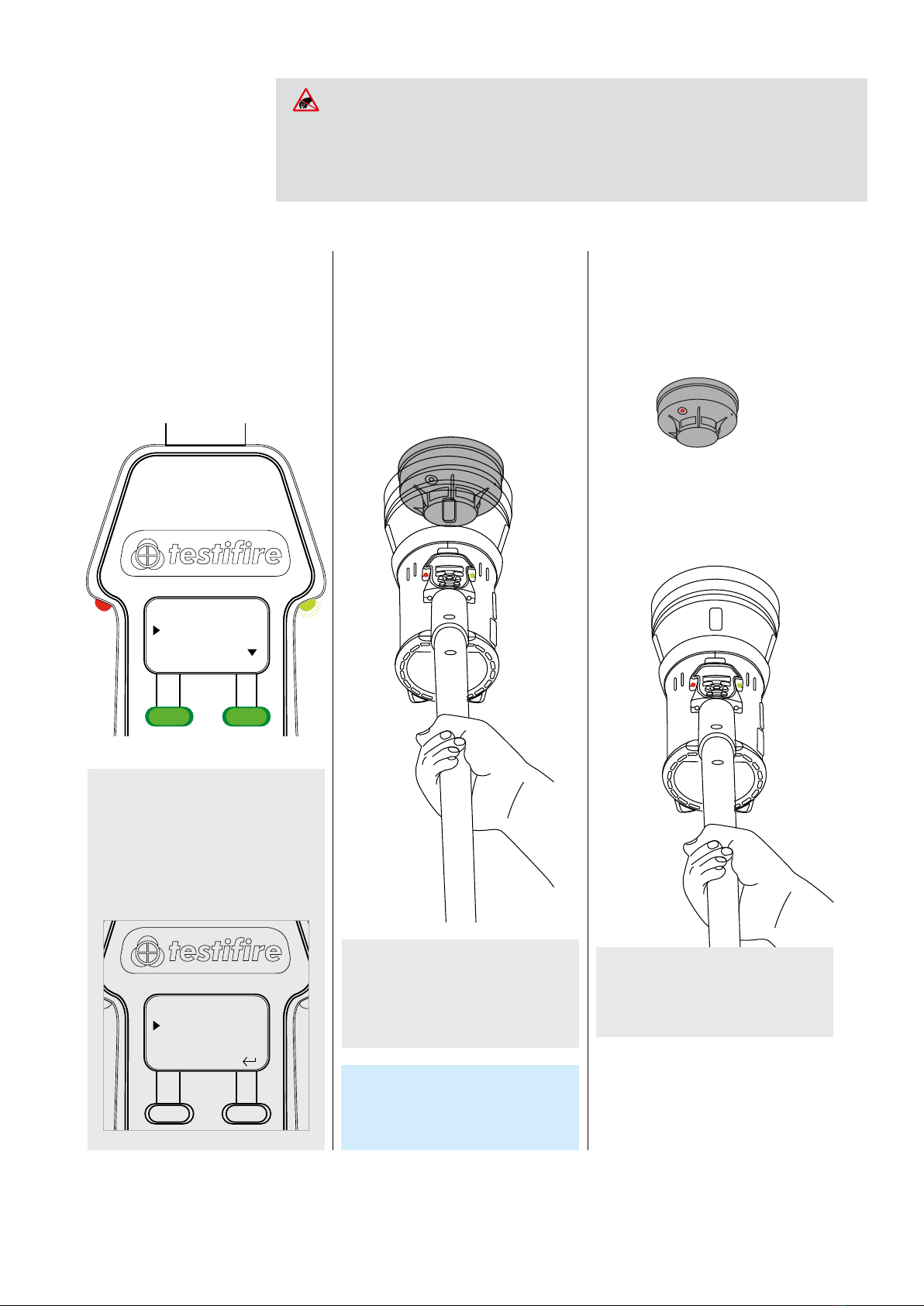
5.1 DEFAULT SMOKE TEST
1
After you have completed the preparation
procedures, Testire will be ready for use.
Select smoke test from the main menu by
moving the cursor to Smoke.
3
When the detector is activated,
remove Testire by lowering it gently.
Testire will return to idle.
Smoke
Heat
CO
Menu Status
NOTE
With smoke selected, pressing the status
key will display the smoke capsule level.
NOTE
The amount of smoke produced may
very throughout the test
NOTE
During a smoke test a slight ‘popping’
sound may be heard. This is normal and
part of the test procedure.
Smoke Status
Capsule Level
5SINGLE TEST
Smoke
Heat
CO
Menu Status
A test cannot be carried out if the
capsule is empty
CAPSULE LEVEL SYMBOLS:
Capsule Problem
Capsule Level Low
Capsule Empty
NOTE
If after 2 minutes the test has not
completed, Testire will time-out, highlighted
by the status LED ashing Red/Green
2
An infrared beam across the clear cup
controls the test. The test will begin
automatically when the head unit is
placed over the detector, breaking the
infrared beam.
The test LED will ash Blue to indicate
that smoke is being generated. The
status LED will ash fast Green to show
test in progress
14 www.detectortesters.com/testire
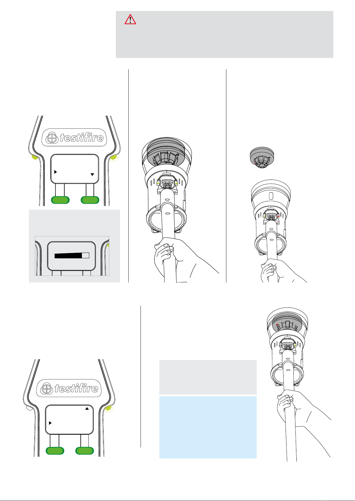
5.2 HEAT TESTING
1
Select Heat test from the main menu by
moving the cursor to Heat. The Test LED
will turn Red, indicating Testire is ready to
perform a Heat test.
2
The test will begin automatically
when the head unit is placed over the
detector, breaking the infrared beam.
The test LED will ash Red to indicate
that heat is being generated.
3
When the detector is activated,
remove Testire by lowering it gently.
Testire will return to idle.
Smoke
Heat
CO
Menu Status
NOTE
Heat is produced in a narrow stream and
is not intended to heat the whole inner
clear cup. Heat should be directed to the
thermal sensor of the detector.
AVOID PLACING HANDS NEAR THE DUCT OUTLET DURING HEAT TESTING OR WITHIN
5 MINUTES OF CONDUCTING HEAT TESTING. HOT AIR IS EMITTED FROM THE DUCT
AND THE TOP OF THE DUCT WILL GET HOT TO THE TOUCH.
CAUTION
Heat Status
Hi Heat
Timer
Off
Off
NOTE
Pressing the Status key will display Heat
status. Here you can prepare Testire for
Hi-Heat (up to 100°C) by pressing the enter
key and then pressing the staus key.
The Timer option if selected stops the heat
test at 60 seconds, complying with NFPA 72.
TIP
Rotating Testire around the detector can
speed up a test on detectors with offset
thermistors.
NOTE
If after 2 minutes the test has not
completed, Testire will time-out, highlighted
by the status LED ashing Red/Green
15
www.detectortesters.com/testire
NOTE
Clearing has a maximum time of 2 minutes.
After 2 minutes Testire will timeout, high-
lighted by the status LED ashing Red/Green
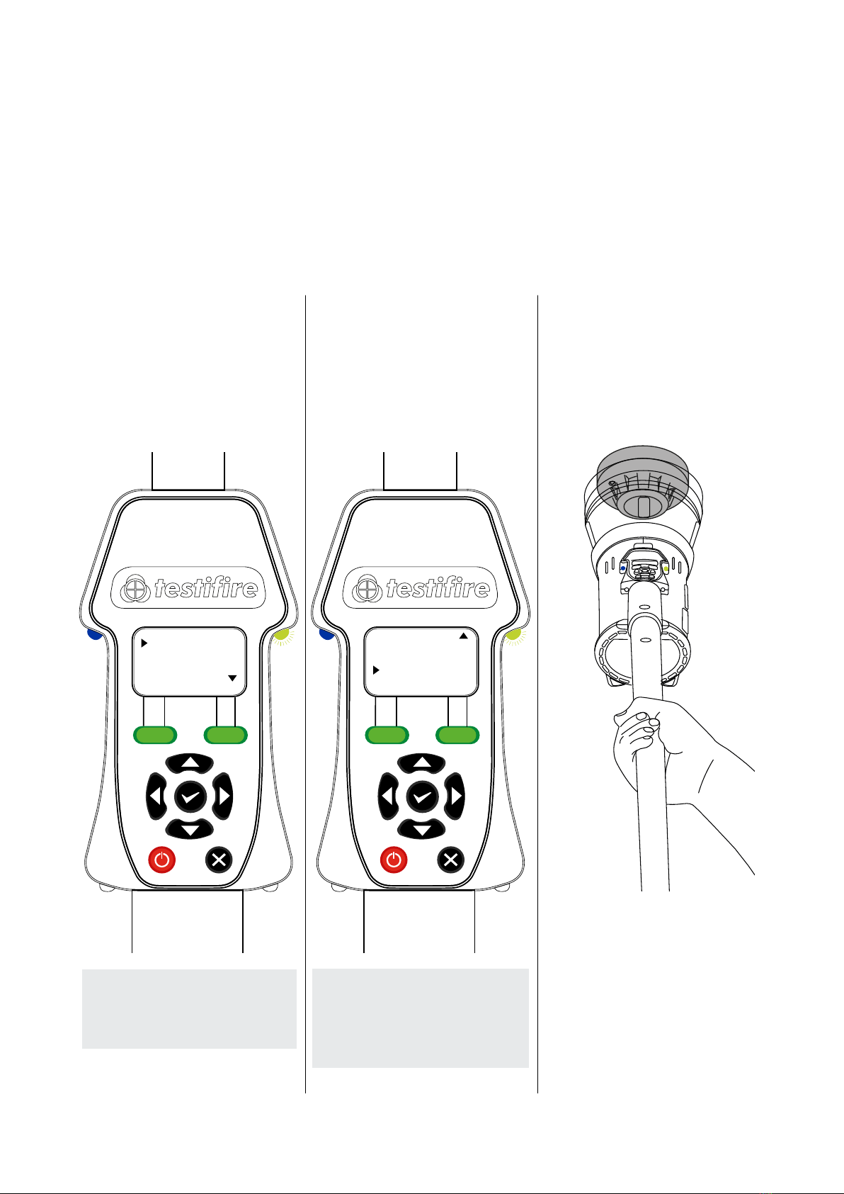
5.3 CO TESTING
5.3 CLEARING A DETECTOR
1
Select Clear from the main menu. This
operation will clear the smoke after a smoke
test. It will not clean the internal components
of the detector
2
Clearing will begin automatically when the head
unit is placed over the detector, breaking the
infrared beam.
The test LED will not illuminate during clearing.
Heat
C0
Clear
Menu Status
TIP
Set Clear as part of a sequential test with
Smoke e.g. Smoke is 1and Clear is set to
2. This will speed up the testing of smoke
detectors as the clearing process will remove
the possibility of the detector reactivating.
See Section on sequential testing for details
of how to set up a sequential test.
1
Select CO test from the main menu by
moving the cursor to CO. The Test LED
will turn Green, indicating Testire is ready
to perform a CO test.
2
The test will begin automatically
when the head unit is placed over the
detector, breaking the infrared beam.
The test LED will ash Green to
indicate that CO is being generated.
3
When the detector is activated, remove
Testire by lowering it gently. Testire will
cool the CO heater element. The status
LED will ash Green and Red with longer
gaps between the ashes. Once the CO
heater element temperature has been
reduced Testire will return to idle, ready
for the next test.
Smoke
Heat
CO
Menu Status
NOTE
With CO selected, pressing the status
key will display the CO capsule level.
CO Status
Capsule Level
THIS PRODUCT EMITS SMALL AMOUNTS OF CARBON MONOXIDE (CO) GAS WHICH
IS A HARMFUL, ODOURLESS GAS. DO NOT INHALE DIRECTLY FROM THE DUCT
DURING A CO TEST OR WITHIN 5 MINUTES OF CONDUCTING A CO TEST.
WARNING
16 www.detectortesters.com/testire
6SEQUENTIAL TESTING
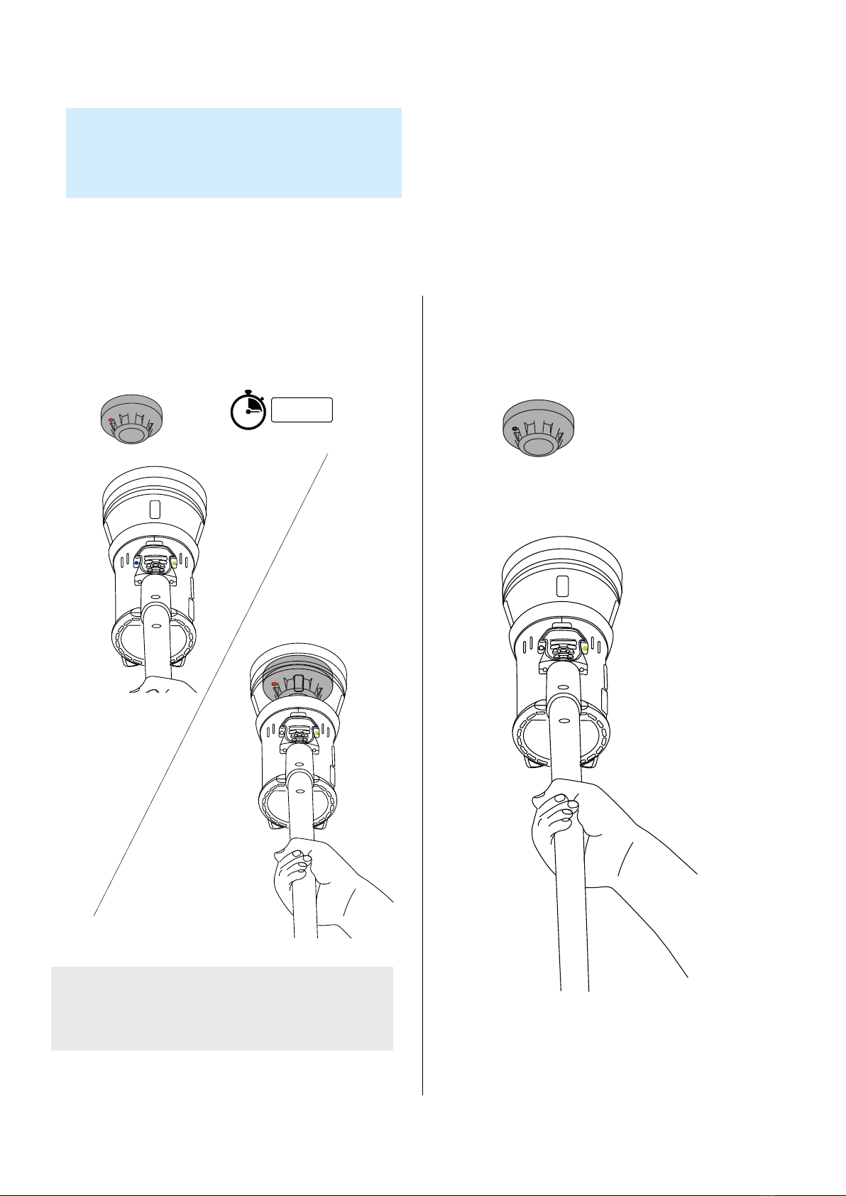
6.1 SMOKE TEST + CLEARING
1
Select smoke test from the main menu
by moving the cursor to smoke. Press the
enter key to select smoke.
2
Move the cursor down to clear and
press the enter key to select clear.
3
The initial smoke test will begin automatically
when the head unit is placed over the
detector, breaking the infrared beam.
Smoke 1
Heat
CO
Heat
CO
Clear 2
Menu MenuStatus Status
Using Testire to carry out a Sequential Test means that a number of operations (Smoke, Heat,
CO and Clearing) can be pre-programmed into the unit before it is raised up to the detector.
This saves time, reduces handling and enables the testing of certain multi-sensor detectors.
NOTE
The rst stimulus selected will be indicated
by the number 1 beside it. The next
stimulus in the sequential test will be
indicated by the number 2beside it.
NOTE
To delete a test sequence, simply press
the escape key to cancel your selection.
17
www.detectortesters.com/testire
4
When the detector is activated, remove Testire by lowering it
gently. After 2 seconds raise again to begin clearing
5
Lower Testire once the detector has been cleared.
Testire will return to idle.
LOWER FOR
2 SECONDS
NOTE
If the detector does not re-enter the cup within 10 seconds,
the test sequence will reset and return to the rst test of the
programmed sequence.
TIP
Any of the test modes can be programmed sequentially in any
particular order before raising to a detector. e.g. [Heat 1, CO 2,
Smoke 3, Clear 4]. Or [Smoke 1, Clear 2, Heat 3,CO 4].

18 www.detectortesters.com/testire
6.2 SMOKE TEST + HEAT TEST
1
Select smoke test from the main menu
by moving the cursor to smoke. Press the
enter key to select smoke.
2
Move the cursor down to heat and
press the enter key to select.
3
The initial smoke test will begin automatically
when the head unit is placed over the
detector, breaking the infrared beam.
Smoke 1
Heat
C0
Smoke 1
Heat 2
CO
Menu MenuStatus Status

19
www.detectortesters.com/testire
4
When the detector is activated, remove Testire by lowering it
gently. After 2 seconds raise again to begin the heat test
5
Lower Testire once the heat test has completed.
Testire will return to idle.
LOWER FOR
2 SECONDS
NOTE
If the detector does not re-enter the cup within 10 seconds,
the test sequence will reset and return to the rst test of the
programmed sequence.
20 www.detectortesters.com/testire
6.3 SMOKE TEST + CLEAR + HEAT TEST
1
Select smoke test from the main menu
by moving the cursor to smoke. Press the
enter key to select smoke.
2
Move the cursor down to clear and
press the enter key to select.
3
Move the cursor to heat and select. All three
tests are now programmed and ready to
begin.
Smoke 1
Heat
CO
Menu Status
Heat
CO
Clear 2
Menu Status
Heat 3
CO
Clear 2
Menu Status
Other manuals for 2000 Series
1
Table of contents
Other Testifire Test Equipment manuals

Testifire
Testifire 2000 Series User manual

Testifire
Testifire XTR2 User manual

Testifire
Testifire 25 User manual

Testifire
Testifire XTR2 User manual

Testifire
Testifire XTR2 User manual

Testifire
Testifire XTR2 Instruction Manual

Testifire
Testifire XTR2 Use and care manual

Testifire
Testifire 1001-1 User manual

Testifire
Testifire 1000 Series User manual
Popular Test Equipment manuals by other brands


MTE
MTE PTS 400.3 PLUS Operation manual

TKR Group
TKR Group VAS 652 005 Operation manual

Beha-Amprobe
Beha-Amprobe UAT-600-EUR Series user manual

Smart Start
Smart Start SmartMobile Insight user manual

Van Der Stahl
Van Der Stahl PTT-100 V operating instructions

Applent Instruments
Applent Instruments Anbai AT8612 user guide


