DIY DSO 138 User manual
Iron(20W)
1
Solderwire
Multimeter
Screwdriver
UserManual
Rev.01
DSO138OscilloscopeDIYKit
2
3
4
Flushcutter
5
Toolsyouneed
Tweezers
6
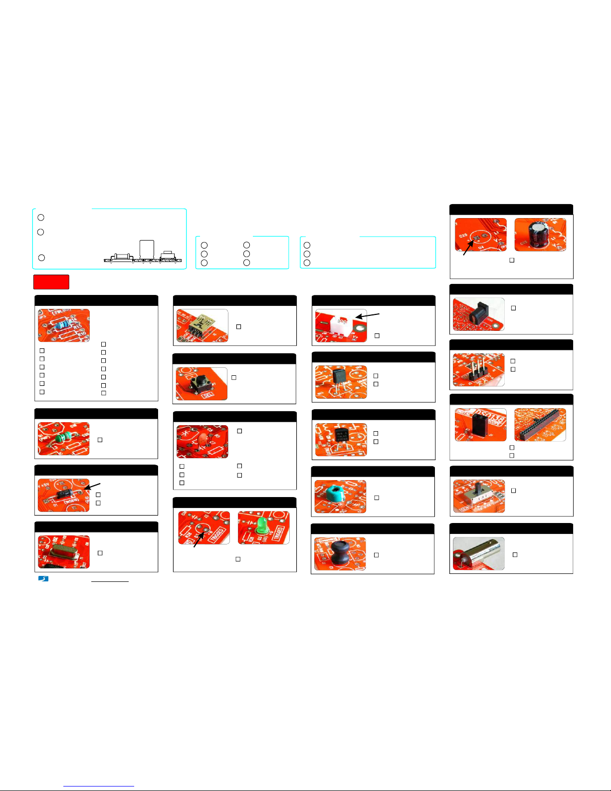
AssemblyMainBoardandLCDboard(followthe orderasnumbered)
Step1
- www.jyetech.com -
JYETechLtd.
1.Resistors
Alwaysmeter resistor
valuesbefore soldering
Note:
R1,R14,R16100K
R21.8M
:
:
R3200K:
R42M:
R520K:
R6300:
R7,R36180
R8,R12,R13
120
:
:
R9,R15,R26
1K:
R103K:
R11,R38
1.5K
:
R28,R40
470
:
R37,R39
10K
:
L1,L3,L4 100Hμ
2.HF-Chokes
:
D1 1N5819
3.Diodes
:
D2 1N4004
:
(or1N4007)
Y1 8MHz
4.Crystal
:
J4 USBmini -B
5.USBSocket*
:
6X 6X 5mm
6.TactSwitches
:
SW4, SW5,
SW6, SW7,
SW8
7.CeramicCapacitors
0.1F
μ
:
330pF:
3pF:
C1,C9,
C10,C11,
C14,C15,
C16,C17,
C18,C20,
C23
1pF:
C7,C8
120pF
:
C12,C13
22pF
:
C2
C3
C5
D3
8.LED
:
φ3mm,green
Solderpositivepole
(thelongerlead)to
thesquarepad
J9 2Pin
9.Pinheader(forpower)
:
Facetheopening
outward
8550
10.Transistors
:
Q1
9014
:
Q2
Cathode
79L05
11.Regulators
:
U4
78L05
:
U5
C4, C6 5-30pF
12.Capacitortrimmers
:
L2 1mH/0.5A
13.Powerinductor
:
14. Electrolyticcapacitors
:
100μ/16VF
Solderpositivepole
(thelongerlead)to
thesquarepad
C19,C21,
C22,C24,
C25,C26
DC005
15. Powerconnector
:
J10
16. Pin-header(male)*
1X 3pin
:
J5
1X 4pin
:
J6
17.Pin-header(female)
:
1X2pin
J7,J8
:
2X20pin
J3
SW1, SW2,
SW3
2P3T
18.Slideswitches
:
J1 BNC
19. BNCconnector
:
Putleadsthroughmountingholesfromthe side with
partoutline.Ensuecomponent evenlytouchPCB.
1
Solderleadsattheotherside.Soldershouldfully
fillandcoversolderingpads.
Avoidbridgesbetween
neighberingpads.
Cut unusedleads
flushwithcutter.
2
3
SolderingHints
Checkpart values&quantitiesagainstpartlist
1
Alwaysmeterresistorvaluesbeforesoldering
Understandallpartpolaritiesandorientations
2
3
Beforeyoustart
*Thesepartsareoptional andnotrequired
forthenormaloscilloscopefunction.
Page1

1
C.Verify
Connectpowersupplyagain.YoushouldseeLCD
lightsupandoscilloscopepaneldisplayed.
2Pressvariousbuttonsandmoveswitchestoverify
theirfunctions.
1)Makeasmallringwitha
leadcut-off.
20.Testsignalring
2X 20pin
22.LCDBoard
:
J1
1X 2pin
:
J2, J3
2)Soldertheringtothetwo
holesofJ2(asshownin
thephoto).
21.JP3
ShortJP3 with solder Note: Installtotheside
oppositeto LCD panel.
TestandUse
Step2
NOTE: Youneeda 9VDCpowersupply(atleast200mAcapacity)
torunthescope.This powersupplyis notincludedinthe kit.
1
A.Checkvoltages
2
3
Apply9VpowertoJ10(orJ9).
2CheckvoltageatTP22.Itshouldbearound+3.3V.
3IfvoltageatTP22isgooddisconnectpower. ShortJP4
withsolder.permanently 1
B.AttachLCDboard
PlugLCDboardintothefemaleheadersJ3, J7, andJ8
onthemainboard.
1
A.Use
AttachprobeclipstoJ1.
2Touchtheredclipwithyourfinger.Doyouseesignal
from yourfinger?
1
- www.jyetech.com -JYETechLtd.
Troubleshooting
IsvoltageatV+
good? Checkpower
supply
IsR36valuecorrect
andsolderedgood?
Doyougetabout3V
betweenJ1pin16&
18onLCDboard?
FixR36
LCDDark
No
No
Yes
Yes
(Nobacklight)
No
Yes
CheckR36and
poweragain
CheckLCD
board
PressSW8. DoesLEDblink? CheckY1, C12, C13
Check LEDinstallation
Check +3.3Vvoltage
Check J3 soldering for
possible opensorshorts
NoDisplay
Yes
No
Check J1 soldering on LCD
board forpossibleopens
orshorts
2
8.60V
9.39V
8.34V
3.3V
-1.39V
2.16V
0.81V
6.43V
0.19V
5.02V
3.3V
4.99V
-5.0V
-8.08V
-8.11V
1.66V0V
*
*
**
*
*
*
**
**
Voltage
References
(InputVoltage)
*:Thesevoltages areinputvoltagedependent.Thevalues
shownweremeasuredwheninputvoltagewas 9.39V.
**:Thesevoltages aremeasuredwhenCPLswitch(SW1)
is settoGNDposition.
NOTES:
Placethenegative penofvolt-meter
heretodovoltagemeasurements.
Theassemblyshouldlooklikethis
afteryouhavefinishedallparts
ShortJP4 ifithasnotbeen
done. SeeStep 2 above.
CheckU2B,U2Cand
relatedpartsaround
thesetwoamplifiers
No
SetCPLswitchtoGND
andmeasure V1andV2.
Aretheycorrect?
CheckR12andC8
Fixthem
ArethevaluesofAV+and
AV-correct?
NoTrace
Yes
No
Yes
Thevoltagesinthephotoareforreferenceonly.
Thevoltagesonyourboardcouldbedifferent.
Buttheyshouldbeclosetothevaluesshown.
NOTE:
www.jyetech.com/forum
TechSupport:
Trigger”LED blinkingtwice
indicatesbooting-upisgood.
Page2
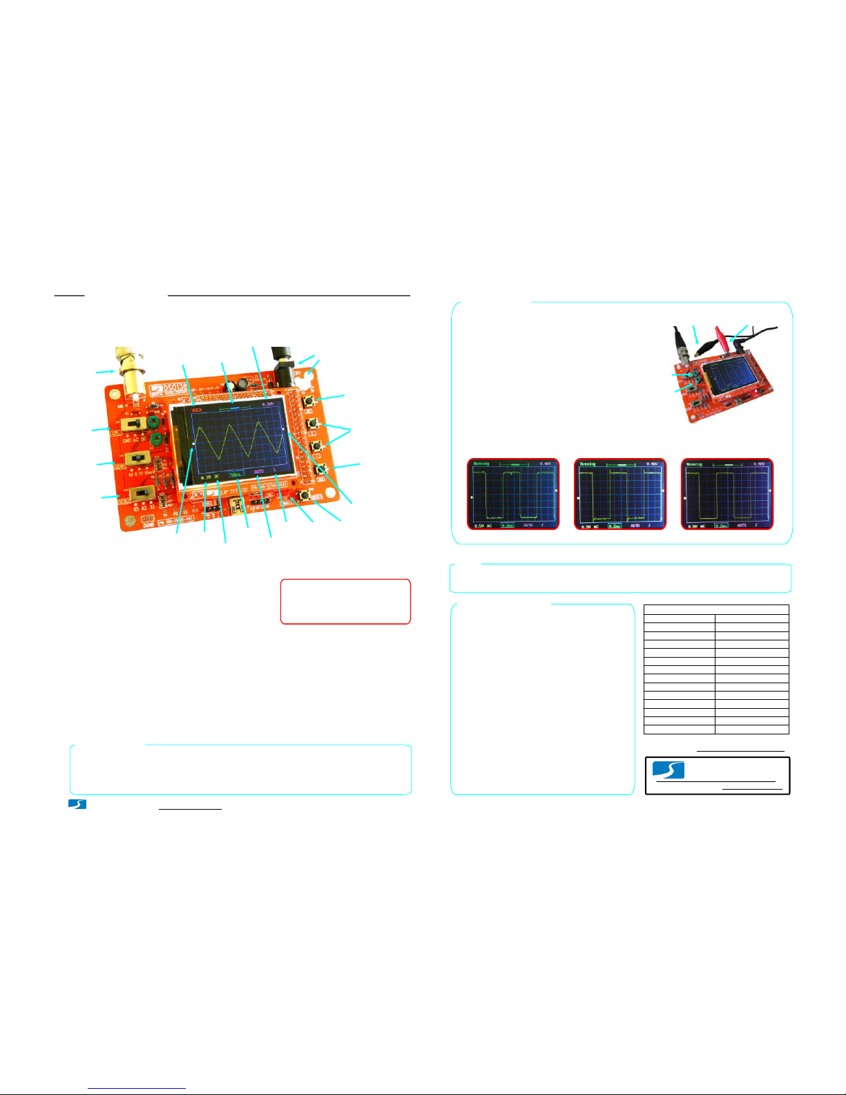
HOLDRUN/
Connectors
forPowerSupply
TriggerLevel
Readout
Horizontal
Position
Oscilloscope
Mode
Connector
forProbe
Couple
Selection
Sensitivity
Selection1
Sensitivity
Selection2
Vertical
Position
Indicator
Sensitivity
Couple
Timebase
Trigger
Mode
Trigger
Slope
Trigged”
Indicator
Trigger
Level
Indicator
Parameter
Selection
Parameter
Adjustment
Reset
Button
[+] or[-]:
[SEL]:
[OK]:
[CPL]:
[SEN1]:
[SEN2]:
HowtoUse
DisplayandControls
Connections
PowerSupply: ConnectDCpowersupply toJ9 orJ10.The power
supply voltage mustbe in the range of8 -12V.
Probe: Connectprobe toJ1.
Powersupplyvoltage mustnotexceed
12V.Otherwise U5willgethot.
Attention
1.
Allowedmaximum signalinputvoltage
is 50Vpk(100Vpp)withthe clipprobe.
2.
Operations
Presson[SEL]button: Selectparameterto be adjusted.The selected parameterwillbe highlighted.
Presson[+]or[-]button: Adjustthe parameterselected by [SEL]button.
Presson[OK]button: Freeze waveformrefresh(entering HOLDstate). Presson itagainwillde-freeze.
Change[CPL]switch: Setcouple to DC,AC, orGND.When GNDisselected the scope inputisisolated frominput
signaland connected to ground (0Vinput).
Change[SEN1]or[SEN2]switch: Adjustsensitivity. The productof[SEN1]and[SEN2]settingsmakesthe
actualsensitivity which isdisplayed atthe lower-leftcornerofthe panel.
Presson[Reset]button: Performasystemresetand re-bootsthe oscillscope.
0VLineAlignment
Sometimesyoumay find the 0Vline (the trace corresponding to 0Vinputvoltage)doesnotmatch withtheVPOS
indicatoratthe screenleftborder.Thiscan easily be fixed by performing the 0Vline alignment”function. First,
setthe couple switch [CPL]to GNDposition.Then presson [SEL]button to makeVPOS indicatorhighlighed and
hold down[OK]button forabout2 seconds.You willsetthe trace aligned to VPOSindicatorwhen yourelease
[OK]button.You may see some residue mismatch remainsatthe highestsensitivity settings.Thisisnormal.
ProbeCalibration
Because there isalwayssome capacitance between scope inputand
groundprobe needsto be calibratedto achieve bettermeasurement
resultsforhigh frequency signals.Thiscanbe done with the help of
the built-in testsignal.Todo thisplease followthe stepsbelow.
Connectredclipto
test signaloutput
Leaveblackclip
un-connected
Connectthe redcliptothetestsignalterminalandleave the
blackclipun-connected(see photoatright).
1.
Set[SEN1]switchto0.1Vand[SEN2]switchtoX5.
Set[CPL]switchtoACorDC.
2.
Adjusttimebaseto0.2ms.Youshouldsee waveformsimilar
tothatshowninphotos below. Iftraces arenotstable adjust
triggerlevel(the pinktriangle onrightscreenborder)soas
yougeta stable display.
3.
TurnC4(capacitortrimmer)withasmallscrewdriversothat
the waveform displays sharprightangle (photoC).
4.
C4
C6
Set[SEN1]switchto1Vand[SEN2]switchtoX1whilekeepallother
settings unchanged.AdjustC6sothatsharprightangle waveform is
displayed.
5.
A –Notenough B –Toomuch C –Good
Analogbandwidth
Sensitivityrange
Resolution
Recordlength
Maxrealtimesamplerate
Timebaserange
Maxinputvoltage
Inputimpedance
Powersupply
Currentconsumption
Dimension
Weight
1MSa/s
0--200KHz
10mV/div-5V/div
50Vpk(1Xprobe)
1Mohm/20pF
12bits
1024points
500s/Div-- 10us/Div
9VDC(8 –12V)
~120mA
117x76x15mm
70gram(withoutprobe)
Triggermodes
Triggerpositionrange
Auto,Normal,andSingle
50%
Specifications
Hints
The LEDatbottom-rightcorner(labelled TRIGGED”)is the triggerindicator.Itblinks whentriggers
are detected.
www.jyetech.com
JYTTechLtd.
Tel.+86-0773-2113856
TriggersandTheirModes
Triggers are events thatindicate signalvoltageacrossing
a setlevel(i.e.triggerlevel)alonga specifieddirection
(i.e. triggerslope,risingorfalling). Oscilloscopeuses
triggers as reference pointsintimeforstable waveform
displayandmeasurements.
Inautomode oscilloscope willperform displayrefreshno
mattertriggershappenornot. Whentriggers aredetected
waveformdisplaywillbedisplayedwithreference to
triggerpoints.Otherwise,displaywaveform atramdom
referencepoints.
AutoMode
Innormalmode oscilloscope willonlyperformdisplay
refreshwhentherearetriggers. Ifnotriggers happen
waveformdisplaywillstayunchanged.
NormalMode
Singlemode is thesame asnormalmode exceptthat
oscilloscopewillenterHOLDstate aftera triggerhas been
detectedandwaveformdisplayhas beenupdated.
SingleMode
Normalandsinglemodes are usefulforcapturingsparse
orsinglewaveform.
Selection
(s/div)
(V/div)
TechSupport: www.jyetech.com/forum
Page3
- www.jyetech.com -
JYETechLtd.
Table of contents
Popular Test Equipment manuals by other brands


Redtech
Redtech TRAILERteck T05 user manual

Venmar
Venmar AVS Constructo 1.0 HRV user guide

Test Instrument Solutions
Test Instrument Solutions SafetyPAT operating manual

Hanna Instruments
Hanna Instruments HI 38078 instruction manual

Kistler
Kistler 5495C Series instruction manual

Waygate Technologies
Waygate Technologies DM5E Basic quick start guide

StoneL
StoneL DeviceNet CK464002A manual

Seica
Seica RAPID 220 Site preparation guide

Kingfisher
Kingfisher KI7400 Series Training manual

Kurth Electronic
Kurth Electronic CCTS-03 operating manual

SMART
SMART KANAAD SBT XTREME 3G Series user manual

Agilent Technologies
Agilent Technologies BERT Serial Getting started