Leuze electronic DB 112 B Parts list manual

DB 112 B
Double Sheet Testing Unit
TECHNICAL DESCRIPTION
en 03-2014/06 50126540
We reserve the right to
make technical changes

Leuze electronic DB 112 B
©2014
Leuze electronic GmbH + Co. KG
In der Braike 1
D-73277 Owen / Germany
Phone: +49 7021 573-0
Fax: +49 7021 573-199
http://www.leuze.com

Leuze electronic DB 112 B 1
Table of contents
1 General information ........................................................................................................... 2
1.1 Explanation of symbols ........................................................................................................ 2
1.2 Declaration of conformity ..................................................................................................... 2
2 Safety notices..................................................................................................................... 3
2.1 Safety standards .................................................................................................................. 3
2.2 Intended use ........................................................................................................................ 3
2.3 Areas of application ............................................................................................................. 3
2.4 Organisational measures ..................................................................................................... 3
3 Device overview ................................................................................................................. 4
4 Specifications..................................................................................................................... 6
5 Mounting the transmitter and receiver............................................................................. 7
6 Electrical connection ......................................................................................................... 8
7 Commissioning ..................................................................................................................9
8 Operation - inputs and outputs....................................................................................... 12
9 Diagnosis in the case of error ........................................................................................ 13
10 Application-specific extension types............................................................................. 14
10.1 VDB 112 B/6.2N - Fixed switching threshold ..................................................................... 14
10.2 VDB 112B/6.12P - without teach button in the cover ......................................................... 15

General information
2 DB 112 B Leuze electronic
1 General information
1.1 Explanation of symbols
The symbols used in this technical description are explained below.
Attention!
This symbol appears before text passages which must absolutely be observed. Failure to
heed this information can lead to injuries to personnel or damage to the equipment.
Notice!
This symbol indicates text passages containing important information.
1.2 Declaration of conformity
The DB 112 B double sheet testing unit sensor system has been developed and manufac-
tured in adherence with the applicable European standards and directives.
Notice!
The corresponding declaration of conformity can be requested from the manufacturer.
The manufacturer of the product, Leuze electronic GmbH + Co. KG in D-73277 Owen/Teck,
possesses a certified quality assurance system in accordance with ISO 9001.
For UL applications:
only for use in "Class 2" circuits according to NEC.

Safety notices
Leuze electronic DB 112 B 3
TNT 35/7-24V
2 Safety notices
2.1 Safety standards
The DB 112 B double sheet testing unit has been developed subject to the applicable safety
standard EN 60947-5-2 (IEC 60947-5-2).
2.2 Intended use
The DB 112 B double sheet testing unit has been conceived as a monitoring device mainly
for paper working machines. It monitors incoming paper sheets at machines designed to
process single sheets. It is used to detect and signal double sheets in the sheet feeder
during operation.
Attention!
The DB 112 B is not a safety module acc. to EU machine guidelines.
The protection of machine and the device cannot be guaranteed if the device is operated in
a manner not corresponding to its intended use.
Access to or changes on the device, except where expressly described in this manual, are
not authorised.
2.3 Areas of application
Double sheets made of the following materials can be reliably detected by the DB 112 B:
• Paper
• Plastic
• Metal foils
For paper, the measurement range is 20g/m² (airmail paper) to 800g/m² (homogeneous
cardboard).
2.4 Organisational measures
All entries in this operating manual must be heeded, in particular those in the section "Safety
notices" and "Commissioning".
Keep this technical description in a safe place. It should be accessible at all times.
Safety regulations
Observe the locally applicable safety regulations.
Qualified personnel
Mounting, commissioning and maintenance of the device may only be carried out by quali-
fied personnel.

Device overview
4 DB 112 B Leuze electronic
3 Device overview
The ultrasonic double sheet testing system consists of a VDB 112 B… analysis amplifier
and a pair of DB 112 UP ultrasonic sensors.
It detects and checks primarily paper, plastic and metal foils which are guided in by feeders.
The device functions as a presence monitor by constantly applying a signal at the single
sheet output when an object is located between the sensors. It functions as a double sheet
testing unit by comparing each sheet with the stored reference value. A detected double
sheet is signalled at the double sheet output.
Figure 3.1: Device overview - dimensions
AM8 connector for transmitter DB 112 UP.1…
BM8 connector for receiver DB 112 UP.1…
CIndicator diodes
DPush button TEACH IN

Device overview
Leuze electronic DB 112 B 5
TNT 35/7-24V
Controls and indicators
Figure 3.2: Controls and indicators
Order guide
Accessories
Designation Model Part No.
Sensor pair M12 x 21mm, cable length 1.5m DB 112 UP.1-20,1500 501 08999
Sensor pair M12 x 21mm, cable length 2.5m DB 112 UP.1-20,2500 501 09000
Amplifier (positive logic) VDB 112 B/6P 501 07002
Designation Model Part No.
Cable 5m, PVC, 5-pin, with M12 connectors K-D M12A-5P-5m-PVC 501 04557
ALED green/yellow/red TEACH IN
BYe l l o w L E D SINGLE SHEET
CRed LED DOUBLE SHEET
TPush button TEACH IN (not for VDB 112 B/6.2N)
VDB 112 B/6P
VDB 112 B/6.2N

Specifications
6 DB 112 B Leuze electronic
4 Specifications
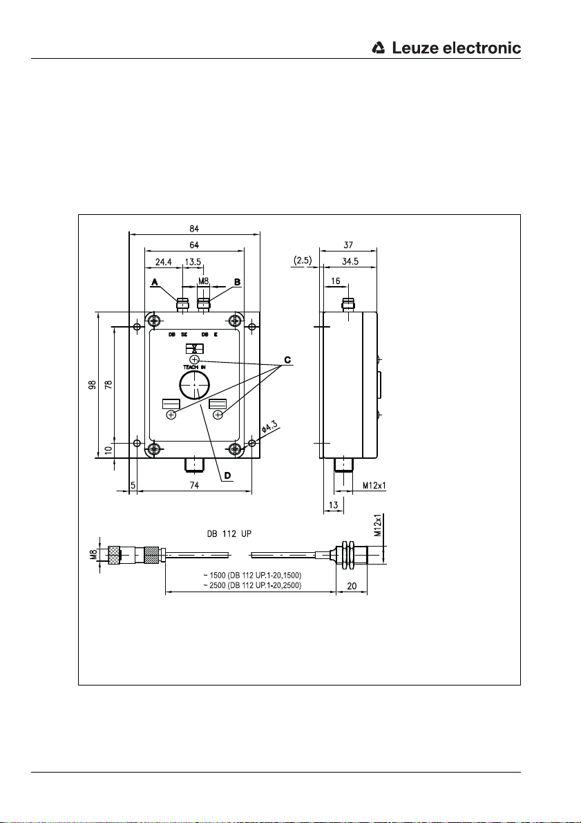
Technical data for sensor DB 112 UP
Technical data for analysis amplifier VDB 112 B/…
Sensor data
Operating range 15 … 30mm
Converter frequency 300kHz ±5%
Ultrasonic lobe approx. 12°
Mechanical data
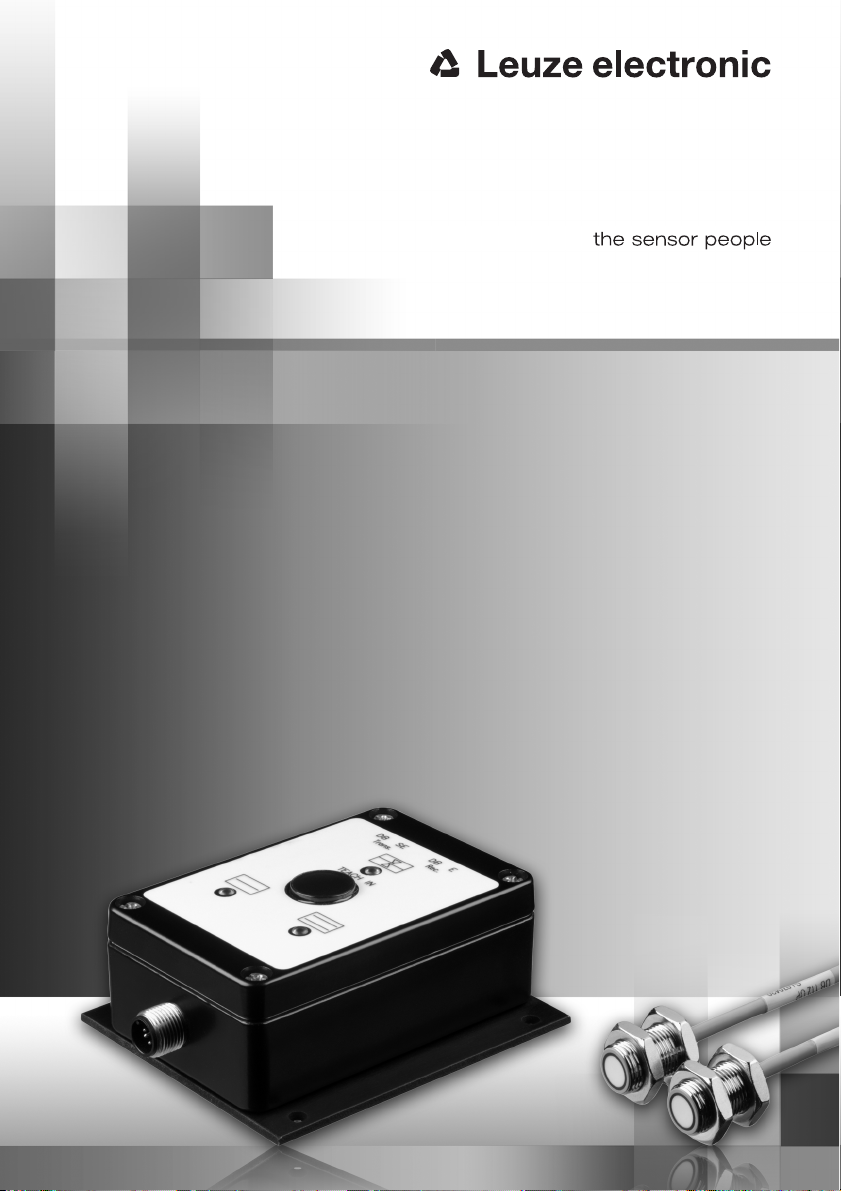
Housing nickel-faced brass
Weight 30g
Connection type 1.5/2.5m cable with M8 connector,
3-pin, bending radius r > 25mm
Timing
Switching frequency 200Hz
Input pulse min. 5ms
Delay before start-up ≤300ms
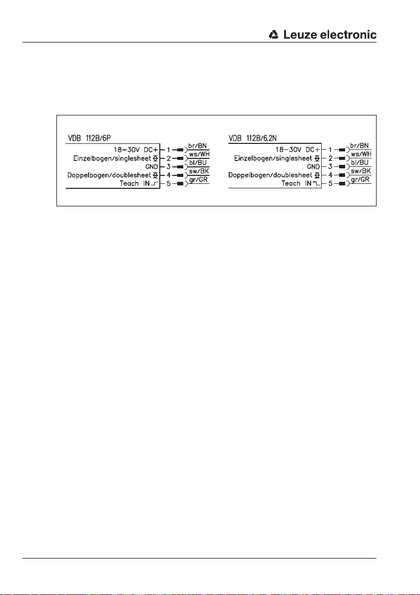
Electrical data
Operating voltage UB1)
1) For UL applications: only for use in "Class 2" circuits according to NEC.
18 … 30VDC (incl. residual ripple)
Residual ripple ≤15% of UB
Open-circuit current ≤75mA
Switching output 2 push-pull switching outputs 2)
2) Function: …/…P = active high (+24V); inactive low (0V),
…/…N = active low (0V); inactive high (+24V).
The push-pull switching outputs must not be connected in parallel
Function single sheet detected, or ≥ 1 sheet
double sheet detected, or ≥ 2 sheets
Signal voltage high/low ≥(UB- 2V)/≤2V
Output current max. 100mA per output
Teach input Rin =10kΩ
TEACH-IN active/not active 3)
3) Setting the Teach IN input disables the TEACH IN button (see page 10)
…/…P (PNP): ≥10V / ≤2V or not connected
…/…N (NPN): ≤2V / ≥10V or not connected
TEACH IN duration max. 100ms
TEACH IN delay 4)
4) Only applies for automatic calibration during sheet movement (automatic teach)
approx. 300ms
Indicators
LED green A double sheet testing unit ready
LED A yellow teach-in process
LED A red flashing error (see chapter 9)
LED yellow B single sheet detected
LED red C double sheet detected
Mechanical data
Housing aluminium, black powder-coated
Weight 400g
Connection type M12 connector, 5-pin
Environmental data
Ambient temp. (operation/storage) 0°C … +50°C / -40°C … +70°C
Protective circuit 5)
5) 1=transient protection, 2=polarity reversal protection, 3=short circuit protection
1,2,3
VDE safety class III
Protection class IP 65
Standards applied EN 60947-5-2
Certifications UL 508, C22.2 No.14-13 1) 6)
6) These proximity switches shall be used with UL Listed Cable assemblies rated 30V,
0.5A min, in the field installation, or equivalent (categories: CYJV/CYJV7 or PVVA/PVVA7)

Mounting the transmitter and receiver
Leuze electronic DB 112 B 7
TNT 35/7-24V
5 Mounting the transmitter and receiver
The transmitter and receiver (DB 112 UP) are identical in construction and are to be
mounted according to the table in figure 5.1 at an angle which varies depending on the sheet
material. A larger angle of inclination increases the flutter range; e.g. with a 35° pitch, flutter
is permissible within 50% of the measurement field. The distance between transmitter and
receiver must be at least 15mm and can be max. 30mm.
Ensure that alignment is exact (±1°). If the alignment does not run along the axis, the
working range is reduced.
Notice!
When aligning the transmitter and receiver, take care to ensure the most exact alignment
possible. See "Alignment mode" on page 9. To ensure proper function, the sensors must be
inclined by the angle "B" towards the vertical.
Figure 5.1: Mounting the transmitter and receiver
Figure 5.2: Recommended configuration for maximum functionality
AReceiver
BAngle of inclination
CSheet material
DTransmitter
Sheet material Recomm. angle of inclination B
0° 15° … 25° 25° … 35°
Standard paper up to 150g/m² X X X
Cardboard X X
Plastics X
AReceiver
BMachine direction
CSheet material
DTransmitter

Electrical connection
8 DB 112 B Leuze electronic
6 Electrical connection
Connect the transmitter and receiver at the appropriate M 8 connectors of the VDB 112 B/…
analysis amplifier.
Connect the analysis amplifier acc. to connection diagram (figure 6.1).
Figure 6.1: Connection diagram VDB 112 B/…
Circuit logic
VDB 112B/…P -> positive logic
VDB 112B/…N -> negative logic

Commissioning
Leuze electronic DB 112 B 9
TNT 35/7-24V
7 Commissioning
Notice!
If the indicators flash during the initial commissioning, a calibration must first be performed
on a single sheet.
First apply operating voltage. An alignment mode is available for commissioning. This can
be used to check the alignment of the transmitter and receiver.
Alignment mode
Notice!
After exiting alignment mode, it is absolutely necessary to perform a calibration.
Press the TEACH IN button
for>5sand<10s LEDs and flash synchronously at 3Hz
LED green:Alignment
OK
Exit:
press the TEACH IN button < 5s
LED yellow:Alignment
critical
Align transmitter and receiver until
LED is green.
Only then is it possible to exit align-
ment mode!
Extraordinary exiting of alignment
mode is possible only by means of
Power OFF!
LED red:Alignment
bad
Align transmitter and receiver until
LED is green.
Only then is it possible to exit align-
ment mode!
Extraordinary exiting of alignment
mode is possible only by means of
Power OFF!

Commissioning
10 DB 112 B Leuze electronic
Calibrating on the material to be detected
For reliable detection of double layers of the medium being processed, it is always neces-
sary to perform a calibration on a single sheet of the medium.
Calibration of the material to be detected can be performed by either pressing the TEACH IN
button on the analysis amplifier for 0.3s to 5s or by means of a control command at the
Teach IN input (pin 5).
Notice!
Setting the Teach IN input (pin 5) disables the TEACH IN button. As soon as a signal is ap-
plied once via the Teach IN input for the purpose of calibration, the TEACH IN button re-
mains inactive (disabled) until the next Power On.
During the calibration process, LED illuminates yellow.
If the calibration was successful, LED illuminates green and LED yellow. The
single sheet output is activated. The reference value remains stored until the next calibra-
tion process.
If the calibration process was not successful, LED flashes red and LED illuminates
red. The double sheet output is activated.
Notice!
Causes of unsuccessful calibration include e.g.:
• More than 1 sheet between the sensors.
• Unsuitable sheet material, e.g. due to lamination or coating, too thin, too thick, or air
pockets present.
• Pitch to sensors too low.
The VDB 112 B analysis amplifier can be operated in 3 different operating modes (teach
modes):
1. Standard mode:
Teach with intelligent transmitter/receiver control for covering a wide spectrum of
materials.
2. Automatic teach:
300ms after sheet detection by the ultrasonic sensors, teach-in occurs automatically.
In this operating mode, manual or external teaching is not necessary. A new auto-
matic teach-in is carried out if the ultrasonic path is clear for more than 2s.
3. Fixed switching threshold:
This operating mode is recommended when the process does not permit manual or
external teaching. In this operating mode, the variety of materials to be detected is
limited.

Commissioning
Leuze electronic DB 112 B 11
TNT 35/7-24V
Selecting the operating mode (teach mode)
Attention!
After selecting the operating mode (teach mode), a calibration must be performed!
Press the TEACH IN button
for > 10s and < 15s LEDs and flash alternately at 3Hz
1. LED green: Manual teach
(standard mode)
To select and exit:
press the TEACH IN button > 3s
(LED yellow)
To advance to next:
press the TEACH-IN button < 3s
2. LED red: Automatic teach
on the first sheet
To select and exit:
press the TEACH IN button > 3s
(LED yellow)
To advance to next:
press the TEACH-IN button < 3s
3. LED off:
Permanently
stored switching
threshold
To select and exit:
press the TEACH IN button > 3s
(LED yellow)
To advance to next:
press the TEACH-IN button < 3s

Operation - inputs and outputs
12 DB 112 B Leuze electronic
8 Operation - inputs and outputs
The analysis unit VDB 112 B/… continuously signals the situation occurring between the
sensors to two outputs.
The single sheet output (pin 2) is activated as long as one or more sheets are located in
the measurement field.
The double sheet output (pin 4) is activated as long as two or more sheets are located in
the measurement field.
Notice!
For reliable operation, it is essential that calibration be performed on the material to be
detected. See "Calibrating on the material to be detected" on page 10.

Diagnosis in the case of error
Leuze electronic DB 112 B 13
TNT 35/7-24V
9 Diagnosis in the case of error
The device LEDs indicate the following error states:
LED LED LED Meaning Cause Remedy
red
flashing
(6Hz)
yellow
flashing
(6Hz)
Double-sheet con-
trol not calibrated Perform calibration
red
flashing
(6Hz)
red
No single sheet
detected during cali-
bration
No sheet inserted or
double sheet
inserted
Calibrate on single
sheet
red
flashing
(6Hz)
red
flashing
(6Hz)
Amplifier detects
insufficient input sig-
nal when device
switched on
Sheet between the
sensors or sensors
not connected
Remove sheet and
acknowledge with
the TEACH IN button
red
flashing
(6Hz)
red
flashing
(6Hz)
Amplifier detects
excessively high
noise level when
device switched on
Extreme back-
ground noise
Dampen back-
ground noises, e.g.
using foam
rapid
yellow
flashing
rapid
red
flashing
Current at output too
high Short circuit Switch off voltage,
check wiring
red
flashing
(3Hz)
red Fatal memory error Defect Have repaired by
Leuze electronic

Application-specific extension types
14 DB 112 B Leuze electronic
10 Application-specific extension types
The amplifier types described below are used for the adaptation to specific applications.
They are used instead of the standard amplifier types.
10.1 VDB 112 B/6.2N - Fixed switching threshold
This amplifier corresponds to the VDB 112B/6P with regard to the technical and electrical
data. The software is adapted to a special customer application.
No calibration is needed for the material to be detected as a fixed switching threshold for
double sheet detection is implemented in the amplifier.
The detection range covers papers between 40g/m² and 450g/m².
Notice!
The VDB 112 B/6.2N has no TEACH-IN button. In order to enter alignment mode if required,
the 2-pin pin strip directly on the PCB may be bridged for >5s. Afterwards, alignment can be
carried out as described under "Alignment mode" in chapter 7.
The device LEDs indicate the following error states:
In the case of VDB112B/6.2N, the operating voltage must be interrupted briefly in order to
reset the error message.
Designation Model Part No.
Amplifier (negative logic) - fixed switching threshold VDB 112 B/6.2N 501 07003
LED LED LED Meaning Cause Remedy
red
flashing
(6Hz)
red
flashing
(6Hz)
Amplifier detects
insufficient input sig-
nal when device
switched on
Sheet between the
sensors or sensors
not connected
Remove sheet
red
flashing
(6Hz)
red
flashing
(6Hz)
Amplifier detects
excessively high
noise level when
device switched on
Extreme back-
ground noise
Dampen back-
ground noises, e.g.
using foam
rapid
yellow
flashing
rapid
red
flashing
Current at output too
high Short circuit Switch off voltage,
check wiring
red
flashing
(3Hz)
red Fatal memory error Defect Have repaired by
Leuze electronic

Application-specific extension types
Leuze electronic DB 112 B 15
TNT 35/7-24V
10.2 VDB 112B/6.12P - without teach button in the cover
This amplifier corresponds to the VDB 112B/6P with regard to technical and electrical data
as well as the software. The devices are delivered with "manual teach" operating mode.
The calibration on the material to be detected is performed using pin 5 on the M12
connector.
Notice!
To enter alignment mode, the 2-pin pin strip directly on the PCB can be bridged for longer
than 5s. Afterwards, alignment can be carried out as described in chapter 7. Error states see
chapter 9 "Diagnosis in the case of error".
Designation Model Part No.
Amplifier (positive logic) without teach button in the cover VDB 112 B/6.12P 501 09780
Table of contents
Popular Test Equipment manuals by other brands

EXFO
EXFO FOT-12 instruction manual

Rohde & Schwarz
Rohde & Schwarz R&S RTO Series Getting started

KAPSCH
KAPSCH T600 Operator and maintenance manual

JDS Uniphase
JDS Uniphase IP Video Test Option HST-3000 Testing Guide

Chipatronic
Chipatronic CH-CT5HD quick start guide

SONNECT
SONNECT Sound bullet user manual

VeEX
VeEX V-SAM VePAL V300 Quick reference guide

Vivosonic
Vivosonic Integrity V500 quick reference

Rohde & Schwarz
Rohde & Schwarz R&S CMW-KM70 Series user manual

Alcohol Countermeasure Systems
Alcohol Countermeasure Systems Alcolock LR Installation and service manual

PICO
PICO ADC-10 user manual

MSW Motor Technics
MSW Motor Technics MSW-FIPT-01 user manual