TESTING 2 0231 User manual

TESTING Bluhm & Feuerherdt GmbH
Production and distribution of
construction-material testing devices
Motzener Str. 26b
DE - 12277 Berlin
Tel. +49(0)30/7109645-0
Fax +49(0)30/7109645-98
www.testing.de
1
Operating Manual
Vibrating Table

Vibrating Table
2.0231 / 2.0268 / 2.0269
2.0131 / 2.0233 / 2.0234
2.0271
2
Importance of this Operating Manual:
The operator must read and understand this entire Operating Manual before putting the
machine into operation.
Table of contents: Page:
1. Basic instructions...............................................................................................3
1.1 Designation .......................................................................................................3
1.2 Purpose for which this system was designed....................................................3
1.3 Conditions under which this Vibrating Table may not be used..........................4
1.4 Guarantee.........................................................................................................4
1.5 Safety regulations..............................................................................................5
1.5.1 General regulations .......................................................................................5
1.5.2 Obligations of the operator ............................................................................5
1.5.3 Information about the CE symbol...................................................................6
1.6 Acceptance of delivery, transport......................................................................7
1.6.1 Acceptance of delivery...................................................................................7
1.6.2 Transport.......................................................................................................7
1.7 Equipment delivered..........................................................................................7
1.8 Connection to the power supply........................................................................8
2. Device characteristics........................................................................................9
2.1 Mechanical features..........................................................................................9
2.2 Noise emission values.......................................................................................9
2.3 Electric smog...................................................................................................10
2.4 Standard vibrating tables without magnetic clamping device ..........................11
2.5 Models with magnetic clamping device...........................................................13
3. Placing the Vibrating Table into operation.....................................................15
4. Operation...........................................................................................................15
5. How to set the timer switch ST64-31.07..........................................................16
5.1 General description.........................................................................................16
5.2 Setting the timer-switch parameters................................................................16
5.3 Setting the time for the timer to run.................................................................17
5.4 Explanation of the display ...............................................................................18
6. Inspection and maintenance............................................................................18
7. Troubleshooting................................................................................................19
8. Decommissioning.............................................................................................19
9. Scrapping, disposal..........................................................................................19
10. After-sales service............................................................................................21
10.1 Date of this version of the Operating Manual..................................................21
10.2 Copyright.........................................................................................................21
10.3 Spare parts and technical help........................................................................21
Enclosures:
European Union Declaration of Conformity
Circuit diagram
Testing and Measuring Record

Vibrating Table
2.0231 / 2.0268 / 2.0269
2.0131 / 2.0233 / 2.0234
2.0271
3
1. Basic instructions
1.1 Designation
Designation of the device: Please see the name plate on the machine, which
shows the complete characteristic data and the electric
properties of the system.
1.2 Purpose for which this system was designed
This Operating Manual contains the information required for operation of the products
described here, for the purpose for which they have been designed. This Operating Man-
ual is intended to be used only by technically qualified staff.
“Technically qualified staff” is defined as those persons who – as a result of their training;
their experience; the instructions which they have received; as well as their knowledge of
the relevant standards, regulations, accident-prevention regulations, and conditions of
product operation in the company –have been authorized by the person responsible for
the safety of the company equipment to carry out the activities and actions required for
operation of the equipment described below, and who can recognize and prevent any
possible dangers arising from such operation (this definition of technically qualified staff
has been provided).
The User must by all means observe the requirements and limit values, as well as all
safety instructions, given in this Operating Manual. Any use of this device not in conform-
ity with these stipulations shall be considered to be in violation of the use for which this
system was intended. If this device must be operated under special conditions, or with
special modes of operation, then this shall be authorized only after consultation with the
manufacturer, and after obtaining his prior and express approval.
This Vibrating Table may be used only for compaction of fresh concrete that has been
filled into moulds. The user must by allmeans observe the operating instructions, require-
ments, the limit values, and the safety instructions contained in this Operating Manual.
Any use beyond this is considered as improper use.
Caution!
The instructions provided in this operating manual concern only the
correct use of the system. To perform the test correctly, the user must
observe the specific norms for the test.
Please read these instructions carefully, as they describe how the system is oper-
ated safely.
This operating manual is to be regarded as an integral part of the product and
relates only to the system it is supplied with.
Always keep the operating manual in an orderly condition for the entire period the
system is operating. This will to allow you to obtain help easily when required.
If the system is sold, the operating manual must be passed on to the new owner,
along with its annexes.

Vibrating Table
2.0231 / 2.0268 / 2.0269
2.0131 / 2.0233 / 2.0234
2.0271
4
The manufacturer accepts no liability for any damage caused by incorrect use of
the system.
Changes reserved: The manufacturer retains the right to change the technical de-
scriptions as well as the system to which they relate without advance notice.
This operating manual contains safety instructions that are to be observed in order to
exclude any risk of fatalities, injuries, damage to the equipment or improper operation.
Safety markings are as follows:
Caution!
This warning refers to dangers that could cause material damage.
Danger
This warning refers to dangers that could cause severe injuries or
even fatalities.
Note
Provides practical advice on operation
1.3 Conditions under which this Vibrating Table may not be used
This Vibrating Table is not designed for operation under the following conditions, and may
therefore not be used in such cases:
The Vibrating Table must not be used on a surface that is not level. And on a surface
that cannot safely support its weight or the forces that it produces.
The Vibrating Table may not be subjected to unbalanced loads or weights (i.e., loads
or weights only on one side).
The Vibrating Table may not be used under dangerous, adverse, or any other unfa-
vourable conditions.
Persons must not step or stand on the table while it is in operation, or while it is shut
off.
1.4 Guarantee
Our General Terms of Sales and Delivery apply in all cases.
The Manufacturer guarantees that this Operating Manual has been prepared in conform-
ity with the technical and functional parameters of the machine as delivered. The Manu-
facturer reserves the right to add supplementary information to this Operating Manual as
required.

Vibrating Table
2.0231 / 2.0268 / 2.0269
2.0131 / 2.0233 / 2.0234
2.0271
5
The guarantee provided by the Manufacturer is the legal guarantee. This guarantee does
not cover wear-and-tear parts.
The Manufacturer guarantees trouble-free operation onlyif the User observes the instruc-
tions in this Operating Manual, and only if the User employs the machine for the purpose
for which it is intended.
The Manufacturer shall not be liable for damages that may occur if the machine is used
for purposes for which it is not intended, or if the User does not observe the instructions
and rules for operation as set forth in this Operating Manual.
No claims for damages may be lodged against the Manufacturer if the machine is modi-
fied in its structural or constructional characteristics without the prior written consent of
the Manufacturer, or if its functional characteristics are modified without such consent.
1.5 Safety regulations
1.5.1 General regulations
Precise information about all of the safety regulations and warnings that are contained in
these operating instructions, as well as their problem-free technical implementation, are
a requirement for the safe installation, putting into operation, safe usage and maintenance
of TESTING products. Therefore, it is absolutely necessary that all measures are carried
out by qualified personnel. All personnel who are involved with the project planning, in-
stallation and operation must be familiar with the safety concepts and qualified in such
matters.
Qualifications of the operating personnel
Only trained technical personnel are permitted to put the machine into operation and to
operate the machine.
Furthermore, the following requirements apply:
Operating personnel must be physically and mentally capable.
They must have been instructed in the independent operation of the device.
They must have been instructed in the intended usage of the device.
They must be familiar with the necessary safety devices.
They must have been authorised to put the devices and systems independently
into operation in accordance with the standards of safety engineering.
They must have been designated by the employer for independent work with the
device.
1.5.2 Obligations of the operator
The person operating the device must ensure that both themselves and other people are
not endangered. Only persons who have been instructed in the operation of the device
may operate the device independently.

Vibrating Table
2.0231 / 2.0268 / 2.0269
2.0131 / 2.0233 / 2.0234
2.0271
6
If the operating safety of the device is impaired by defects or damage, the device should
be taken out of operation immediately and should only be used again after all of the
sources of danger have been dealt with.
Check to see whether the specificationthat is given on the identification plate corresponds
with your mains voltage. Connect only to alternating current.
Use the device only for the applications that are described here. Improper usage will lead
to the loss of guarantee cover.
If the device or the power supply line is damaged, then remove the power plug immedi-
ately.
The unit has been built with the latest technology and according to the approved technical
regulations. However, when it is used, it could lead to dangers for life and limb for the
operator or for a third party, or to impairments or damage to machine technical compo-
nents or to other material assets.
Manipulations and modification to the machine (electrical and mechanical alterations,
etc.) that have not been authorised with the written agreement of the manufacturer shall
be considered to be forbidden and the manufacturer shall accept no claims for damages.
The machine must be positioned at a location that is fire proof and explosion proof.
1.5.3 Information about the CE symbol
TESTING Bluhm & Feuerherdt GmbH testing devices carry the CE symbol.
The CE marking confirms that the product conforms with the EC Directives that must be
taken into consideration for the product and also that the product is in compliance with
the “essential requirements” that are defined therein, and the defined general relevant
level of protection. The conformity-assessment procedure has in each case been carried
out in accordance with the applicable EC Directives. Decisive here is Council Decision on
the modules to be used in the technical harmonisation directives for the various phases
of the conformity-assessment procedure and the regulations for the mounting and usage
of the CE mark.
To confirm the conformity with EU Directive 2014/30/EC on Electromagnetic Compatibility
(EMC), our products are tested in accordance with the EMC requirements for emitted
interference and interference immunityfor electrical measurement, control, regulation and
laboratory devices.
Compliance with the safety requirements in residential areas, commercial and light indus-
trial areas as well as small businesses (residential areas and buildings that are connected
directly to the public low voltage power supply network) as well as the safety requirements
in the industrial area, is fulfilled. Our strict regulations regarding performance level and
the considerable efforts made in development and inspections underline the efforts that
we make to guarantee the high level of qualityof our products, even under difficult electro-
magnetic conditions.

Vibrating Table
2.0231 / 2.0268 / 2.0269
2.0131 / 2.0233 / 2.0234
2.0271
7
Practice has also shown that even CE marked devices such as monitors or displays can
be affected when their manufacturers accept such an influence (e.g. the flickering of dis-
plays) as the minimum quality under EMC conditions. For this reason and in your own
interests, we would recommend that you keep a minimum distance of approximately 1
metres to such devices.
1.6 Acceptance of delivery, transport
1.6.1 Acceptance of delivery
When accepting delivery of the product, first inspect it for its outer, visible condition. If this
inspection is satisfactory, the product may be accepted from the freight forwarder (rail-
ways, parcel service, or other haulage company).
If there are no shortcomings, and if there are no transport damages, then use the bill of
delivery to make sure that the consignment is complete, and that all parts have been
delivered.
If you assume or suspect transport damage, or if transport damage becomes apparent
only after you have accepted the delivery, immediately make an exact report of the con-
ditions and any damage as they exist. Send us this report immediately by fax or e-mail.
Important: Absolutely do not make any changes to the delivered goods.
After we have studied your report, we can make a decision whether we can:
- Deliver spare parts to you, or
- Send a specialized fitter/installer to your plant, or
- Ask that you return the product to us for repair.
1.6.2 Transport
If you wish to transport the Vibrating Table to another location, or to load it onto a vehi-
cle, you can do so manually if you wish. Or, you can stand it on a pallet vertically and
pick it up with a fork-lift.
Be sure to protect the Vibrating Table at all times from the effects of the weather and cli-
mate.
1.7 Equipment delivered
Vibrating Table, ready for operation, with a power cable
Power cable with a full-rubber, two-pole and earthing-pin plug.

Vibrating Table
2.0231 / 2.0268 / 2.0269
2.0131 / 2.0233 / 2.0234
2.0271
8
1.8 Connection to the power supply
Danger
The machine must be connected to the building power system by
a qualified electrician.
In accordance with the pertinent standards, the yellow-green con-
nection terminal must be attached to the earthing system before
additional electrical connections are made.
Before making the electrical connections, please study the en-
closed wiring diagram. Also check the machine rating plate to
make sure that the ratings of the building power supply conform
to the requirements for voltage, wattage, amperage, and fre-
quency of the machine.
The electrical socket must have a safety device that will protect
the system against over-current. This safety device must satisfy
the stipulations of the relevant standards, and must match the ma-
chine voltage. The technical characteristics of this safety device
must also satisfy the standards that apply in the country in which
the machine is installed.
Caution
The manufacturer of the machine cannot be held liable for any dam-
ages that result because the information here is not observed.
Electrical tolerances:
Actual voltage: 10% of the rated voltage
Frequency: 1% of the rated frequency, continually; 2% of the rated frequency, on a
short-term basis
The manufacturer shall not be liable for damages to persons or property that arise be-
cause the above instructions have not been observed.
Vibrating Table
2.0231 / 2.0268 / 2.0269
2.0131 / 2.0233 / 2.0234
2.0271
9
2. Device characteristics
2.1 Mechanical features
The Vibrating Table is constructed of robust steel plate. The surfaces are powder coated.
Switching on/off depends on the model (see table)
The power connection is provided by a full-rubber, two-pole and earthing-pin plug.
Standard vibrating tables without magnetic clamping device
The root-mean-square (RMS) value for acceleration to which the upper parts of the op-
erator’s body is subjected is not more than 2.5 m/s².
Standard vibrating tables with magnetic clamping device
Caution
The magnets involved are electromagnets, which become magnetised
when voltage is applied. Without voltage, they are non-magnetic.
Timer switch:
The timer switch is set at the factory to 120 seconds.
Minimum timer setting:
1 second
Maximum timer setting:
999 hours
Class of enclosure protection:
IP-65
2.2 Noise emission values
The noise level indicated is not necessarily a safe level for the person operating the de-
vice. The level that the operator is exposed to will be influenced by other factors such as
the amount of time exposed, the surroundings, other devices that have been installed in
the vicinity, etc.
Using the exposure levels, the damage that could be caused by the noise can be evalu-
ated.
Sound emission intensity of the device
< 65 dB(A)
Standard for the above information
EN ISO 3746
Continued usage of the devices/machines together with other loud noises can cause a
high level of exposure. If the operator is exposed to a level of noise of more than 85 dB(A)
daily, it is recommended that they wear safety protective devices such as hearing protec-
tion (headphones). If the operator is exposed to a level of noise of more than 90 dB(A)
daily, it is obligatory for them to wear safety protective devices. Further information can
be found in the guidelines/standards that are valid in the country in which the machine
has been installed.

Vibrating Table
2.0231 / 2.0268 / 2.0269
2.0131 / 2.0233 / 2.0234
2.0271
10
The amount of noise that is caused by the machine is dependent upon a number of dif-
ferent factors, including for example the product, the site of installation, etc.
It is therefore impossible to given a generally valid sound level pressure.
2.3 Electric smog
Electrical fields and alternating magnetic fields have varying effects on people. Magnetic
fields are generated when electrical current flows, are difficult to screen off and penetrate
buildings virtually unhindered, likewise the human body. The vibrating table operates at
50 Hz, namely a frequency at which relatively low levels of energy are transferred.
Electromagnetic fields may cause e.g. headaches, sleep disorders and other minor ail-
ments, but the action of weak magnetic fields on people is unlikely to trigger any acute
health problems.
However, as a precaution, those at risk should maintain a minimum distance of 50 cm.
Generally speaking, the amount of exposure is so low that it is often several orders of
magnitude below the limit values.
The applicable limit value defined for the magnetic field is < 100 micro Tesla and < 5
KV/m for the electrical field.
The device is in the category of work equipment for which the magnetic field emissions
generally do not reach the limit value. However, the emissions generated by the device
itself depend on various factors, e.g. product, installation site etc.
For this reason, it is impossible to specify a generally accepted measurement value.
We recommend that people in the following categories maintain a precautionary safe dis-
tance when working with the vibrating table, namely:
-Those with pacemakers
-Those using data media with magnetic recording
-Those bringing magnetic parts
Vibrating Table
2.0231 / 2.0268 / 2.0269
2.0131 / 2.0233 / 2.0234
2.0271
11
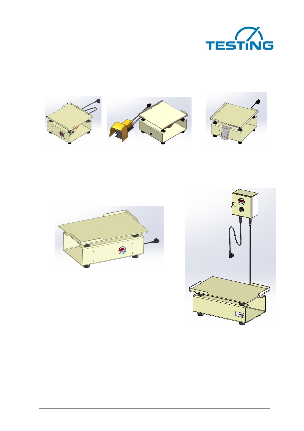
2.4 Standard vibrating tables without magnetic clamping device
2.0131 2.0231 2.0268
2.0269
2.0233
2.0234
2.0271

Vibrating Table
2.0231 / 2.0268 / 2.0269
2.0131 / 2.0233 / 2.0234
2.0271
12
2.0271
600 x 400
255
600 x 400
54
2000-9000
220-240 V / 50 Hz
120 - 130
IP 55
X
2.0234
41
9000
X
2.0233
41
6000
X
2.0269
350 x 350
220
350 x 350
24
9000
X
2.0268
22
3000
< 100
X
2.0231
23
X
2.0131
20
X
Model
Dim.: W x H x D [mm]
Table plate [mm]
weight [kg]
RPM [U/min]
Power supply [V / Hz]
power [W]
Protection class
Pedal switch 2-polig
Timer switch
Manual switch
Vibrating Table
2.0231 / 2.0268 / 2.0269
2.0131 / 2.0233 / 2.0234
2.0271
13
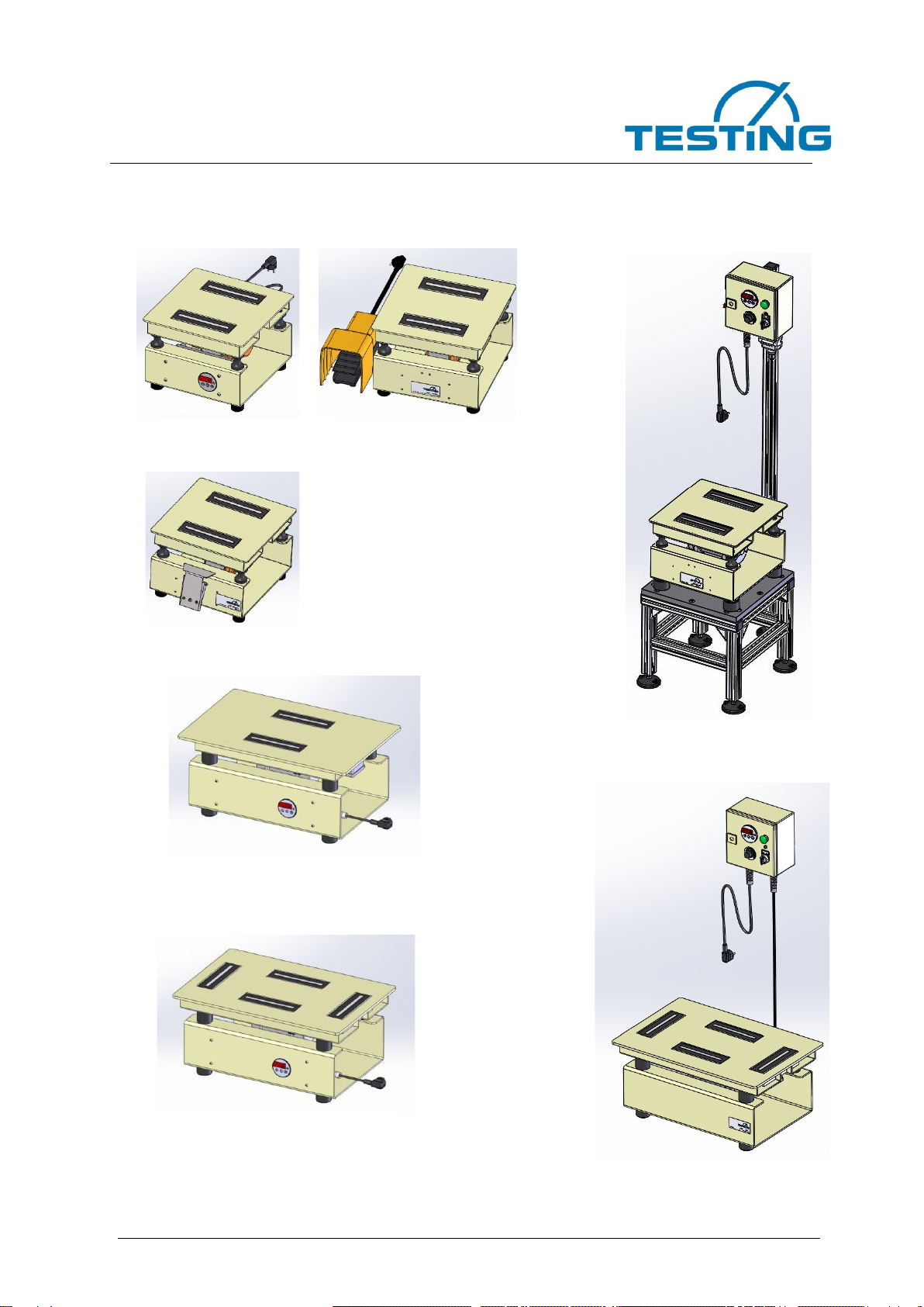
2.5 Models with magnetic clamping device
2.0131M 2.0231M
2.0268M
2.0269RSMU
2.0233M
2.0234M
2.0233M2
2.0234M2
2.0271SM2

Vibrating Table
2.0231 / 2.0268 / 2.0269
2.0131 / 2.0233 / 2.0234
2.0271
14
2.0271SM2
600 x 400
280
600 x 400
63
2000-9000
220-240 V / 50 Hz
150 - 200
IP 55
X
X
2
2.0234M
2.0234M2
56
63
9000
X
1
2
2.0233M
2.0233M2
6000
X
1
2
2.0269
RSMU
350 x 350
1540
350 x 350
72
9000
X
X
1
2.0268M
350 x 350
255
46
3000
130
X
2.0231M
32
X
2.0131M
X
Model
Dim.: W x H x D [mm]
Table plate [mm]
weight [kg]
RPM [U/min]
Power supply [V / Hz]
power [W]
Protection class
Pedal switch 2-polig
Timer switch
Manual switch
Separate Controllerbox
Amount of 150er cube
moulds

Vibrating Table
2.0231 / 2.0268 / 2.0269
2.0131 / 2.0233 / 2.0234
2.0271
15
3. Placing the Vibrating Table into operation
The device may only be operated in dry rooms!
The following limit values apply:
Permissible temperature: from 5 °C to +40 °C
Operating humidity range: from 20 % to 75 % r.H.
Be sure to set up the Vibrating Table on a level surface which can satisfactorily support
its weight and the vibration forces.
Carry out a short functional test by connecting the mains plug to the mains supply.
Caution
We strongly recommend that you use a residual-current-operated
circuit-breaker (RCCB; also known as earth-leakage circuit-breaker,
ELCB) with this Vibrating Table. This device should have a fault-cur-
rent tripping rating of 30 mA.
4. Operation
Danger
Be aware that incorrect inputs to the system can lead to malfunctions,
breakdown of the system, major material damage or to danger to the
operating personnel.
Standard vibrating tables without magnetic clamping device
Place a filled concrete mould on the centre of the vibratory plate of the table, and hold it
securely by hand.
Start the vibration function by using the pedal switch / manual switch or time switch.
During the vibration process, the operator must hold the concrete mould securely by
hand.
After the desired time has lapsed, or after it has become visually apparent that the desired
results have been achieved, stop the vibrationfunction by using the pedal / manual switch
or time switch again.
Attention
Remove overflowing material with a wet cloth. Do not keep the appli-
ance under water. It is only protected against splash water!
Set the desired vibration time (from a minimum of 1 second to a maximum of 9,999 sec-
onds)
Start the vibration function by using the START/STOP button.

Vibrating Table
2.0231 / 2.0268 / 2.0269
2.0131 / 2.0233 / 2.0234
2.0271
16
Models with magnetic clamping device
Place a filled concrete mould on the vibratory plate of the table.
Set the desired vibration time (from a minimum of 1 second to a maximum of 9,999 sec-
onds)
Start the vibration function by using the START/STOP button.
After the pre-selected time has elapsed, or if the Operator presses the STOP button be-
fore this time has run out, the vibration function will stop.
5. How to set the timer switch ST64-31.07
5.1 General description
The microprocessor-controlled timer switch is equipped with a timer with a simple START-
STOP function. When the timer switch is turned on, it displays the time at which it will run
out (the setpoint value). The Operator uses the downward button () and the upward
button () to set the required value for the timer.When the Operator presses the START-
STOP button, the time begins to run. When the elapsed time reaches the setpoint value,
the timer switch will switch off the Vibrating Table. When the time has run out, the auto-
matic-reset function will return the timer switch back to its starting state.
After the timer has started, it can be interrupted at any time and returned to its starting
state. To do this, the Operator presses the START-STOP button.
5.2 Setting the timer-switch parameters
Connect the Vibrating Table with Timer Switch to the power source.
Press the downward button () and the upward button () at the same time and hold
both buttons down for at least four (4) seconds. The display will then show the param-
eter list for timer-switch parameters (beginning with P1).
Use the upward button () to page upward in the list, and use the downward button
() to page downward.

Vibrating Table
2.0231 / 2.0268 / 2.0269
2.0131 / 2.0233 / 2.0234
2.0271
17
By pressing the START-STOP button, you can show the value of the respective pa-
rameter. If you then at the same time also press the upward button () or the down-
ward button () while still holding down the START-STOP button, you can change the
value of the parameter being shown.
When you release all the buttons, this willpermanently save the new value. If you press
no button for longer than 60 seconds, or if you press BOTH the upward button ()
AND the downward button () at the same time for at least four (4) seconds, the sys-
tem will jump back to the original state.
Parameters:
Functional description
Setting range
Default
Customer’s set-
ting
P1
Time range
0: 0 … 999 s
1: 0 … 999 min
2: 0 … 999 h
3: 0 … 999 tenths of
seconds
0
0
P5
Function of input E1
(START/STOP)
0: effective when
closing
1: effective when
opening
0
0
P7
Function of output K1
0: active ON
1: active OFF
0
0
P9
Signal duration of buzzer
0 … 10 s
10
0
P10
Trip for start function
0: button or input
1: only button
2: only input
0
1
P11
Trip for stop function
0: button or input
1: only button
2: only input
0
1
P12
Display of actual time
0: remaining time
1: time elapsed
0
0
P17
Auto reset
0: no auto reset
1: timer has run out:
reset
0
1
5.3 Setting the time for the timer to run
Connect the Vibrating Table with Timer Switch to the power source.
You now set the time for the timer switch to run by briefly pressing the upward
button () or the downward button ().
You can now start the timer switch by pressing the START-STOP button.
Upward
button
Downward button
START-STOP button

Vibrating Table
2.0231 / 2.0268 / 2.0269
2.0131 / 2.0233 / 2.0234
2.0271
18
5.4 Explanation of the display
The very large and especially bright characters simplify checking work and mak-
ing settings, under all conditions.
As a result of the high safety class of the front panel (IP-66), the system can with-
stand water and rough treatment.
Since there are only 3 buttons for the Operator to use, operations and program-
ming are especially simple.
6. Inspection and maintenance
All maintenance work that is concerned with the components of the devices/machines
and the electrical system must be carried out by specialists (trained personnel).
The only maintenance work required for the Vibrating Table is to remove any residual
concrete that may have become adhered to the equipment.
Warning
Any cleaning that is performed using pressurised, sprayed or
splashed water, or bringing water into the control device from dripping
sponges or other similar unsuitable tools or aids will lead to lasting
damage to the mechanical and/or electrical and electronic compo-
nents of the devices/machines.
Electrical current-carrying components are located inside the de-
vices/machines. It is therefore absolutely essential to separate the
machine from the power supply before opening it.
Before maintenance work is carried out, ensure that the device cannot
be turned on again unintentionally by switching the device off and dis-
connecting it from the power supply. Begin the maintenance work only
after the machine has come to a complete stop.
Inspection
Note
The devices/machines must be checked for their industrial safety at
regular intervals. There are national regulations for this that must be
complied with, for example the UVV.
Regular inspections of the correct functioning will supply important in-
formation on the operational condition of the devices/machines.
Daily routine inspections
-mobility
-The connections are in good condition
-Noises
-The condition of the electrical connections
Vibrating Table
2.0231 / 2.0268 / 2.0269
2.0131 / 2.0233 / 2.0234
2.0271
19
7. Troubleshooting
Caution
Work on such electrical equipment may be performed only by suita-
bly trained specialist personnel.
FAULT
CAUSE
REMEDY
Table doesn’t work
Fuses triggered
Electr. system defective
Replace fuses
Check the electrical system by
specialists
Mould not secured,
wobbling on the table
surface
Electr. system defective
Mould not properly centred
The shaping base plate is non-
magnetic
Dampers are defective
Have specialist staff check the
electrical system
Consult suppliers
Replace dampers
Mould cannot be re-
moved
Release of the magnets defec-
tive
Have specialist staff check the
electrical system,
adjust or replace clock timer
In case of malfunction, disconnect the Vibrating Table with Timer Switch from the power
supply.
The Vibrating Table contains no built-in systems to protect against excess current or fault
current. This means that it has no residual-current-operated circuit-breaker (RCCB; also
known as earth-leakage circuit-breaker, ELCB), and no overcurrent trip.
8. Decommissioning
If the system has to be decommissioned for a prolonged period, it must be disconnected
from the power supply.
Perform all maintenance work.
Lubricate unpainted parts and cover the system to protect from dust.
9. Scrapping, disposal
If the system is no longer to be used, the following is recommended.
Disconnect cable from mains supply.
Dismantle system and scrap according to currently applicable legal requirements.

Vibrating Table
2.0231 / 2.0268 / 2.0269
2.0131 / 2.0233 / 2.0234
2.0271
20
The product and the packaging material are made from recyclable materials.
The separate, environment friendly disposal of material residues promotes
the recycling of reusable materials.
This product complies with directive 2012/19/EC of the European Parlia-
ment and Council of Ministers on waste electrical and electronic devices.
The product is labelled with the following symbol:
Instructions on disposal are obtainable from the respective municipality or
local authority.
This manual suits for next models
6
Table of contents
Popular Construction Equipment manuals by other brands


SANY
SANY SCC 2600A manual

Clarke
Clarke CCM125P Operating & maintenance instructions

Central Hydraulics
Central Hydraulics 07620 Assembly and operating instructions

Meec tools
Meec tools 013933 operating instructions

Sealey
Sealey PBS99/10.V3 quick start guide

Ammann
Ammann ARX 36-2 KU St V 2022 operating manual