TEUPEN LEO 18 GT Manual

Version: Leo 18 GT_GB_02-2008
43/2
TABLE OF CONTENTS:
Foreword page 3
1. THE FUNCTION AND FABRICATION page 4
1.1 The function page 4
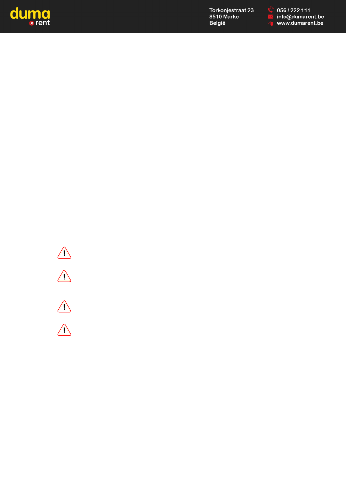
1.2 Technical data page 5
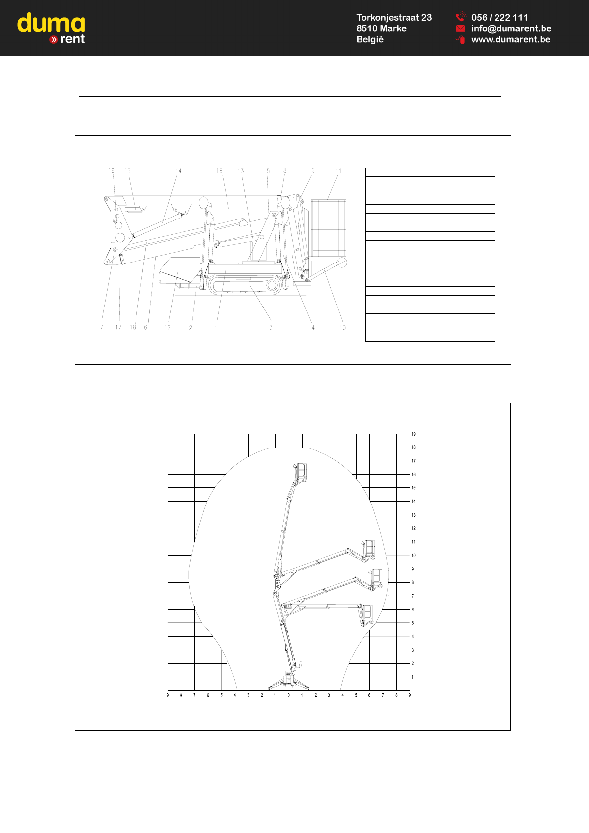
1.3 General description page 7
1.3.1 Frame and the supports page 7
1.3.2 Lifting arm support page 7
1.3.3 Articulated-telescopic arms page 7
1.3.4 Working cage page 8
1.3.5 Controlling of the elevating machine page 8
1.3.6 Rubber caterpillar track running gear page 8
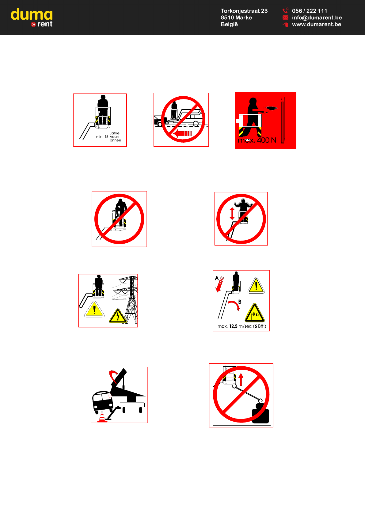
1.3.7 Safety instructions page 9
1.3.8 Meaning of the warning and informative
signs placed on the machine page 10
2. DIRECTIVES OF SAFETY ENGINEERING AND
ENVIRONMENT PROTECTION page 13
2.1 Safety engineering page 13
2.2 Environmental directives page 14
3. HYDRAULIC RUNNING GEAR FOR THE RUBBER
CATERPILLAR TRACKS page 15
3.1 Elevation adjustment of the running gear page 15
3.1.1 Gauge narrowing (narrow gauge) page 15
3.1.2 Gauge widening (wide gauge) page 15
3.1.3 Safety devices page 16
4. HANDLING AND USAGE OF THE MACHINE page 17
4.1 Transporting the machine page 17
4.2 The requirements for the operator page 19
4.3 To be in operation page 20
4.4 Function descriptions of the machine page 20
4.4.1 Disassembling and assembling of the basket page 20
4.4.2 The installation of the power supply of the machine page 21
4.4.3 Traveling with the machine page 25
4.4.4 Stabilizing of the machine page 27
4.4.5 The control and the operating of the superstructure page 28
4.4.6 Emergency control page 29
4.4.7 Working on the slope page 31
4.4.8 Instructions for operating in Winter page 32
4.4.9 Working on electrical equipments and next to the electrical ones page 32
4.5. Instructions after finishing of the operating of the machine page 32
5. MAINTENANCE AND LUBRICATION OF THE MACHINE page 33
5.1 Safety instructions of the maintenance page 33
5.1.1 Lubrication and checking tasks page 34
5.1.2 Bogie maintenance instruction page 35
5.2 Operating trouble and prevention of those page 41
5.3 The maintenance of the explosive engine page 42

Version: Leo 18 GT_GB_02-2008
43/3
Foreword
Buying with this product, you have such an elevating machine which will sure you that
you are able to work about to 17.7 m height /Leo 18GT/ with low operating cost in abso-
lute safe and comfort.
The type Teupen Leo 18 GT is a elevating machine, which is equipped with one electro
hydraulic control, as well as, it is self-powered elevating machine with cage and built-on a
rrubber caterpillar and it can be operated with simple handling.
The type Leo 18 GT self-powered lifting machine with cage, which was constructed that
the operator is able to travel with the machine, to actuate the supports from the cage
and, of course, to work safely a-high.
You can expect a fail-safe operating from the Teupen Leo 18 GT self-powered lifting ma-
chine if before first installation you read thoroughly the operating and maintenance in-
structions which are on the next pages.
Operating guide contains important instructions in connection with the expertise and
economic operating of the elevating machine. Attention of the operator helps to avoid
dangerous situations, reduces the maintenance costs and loss time, furthermore helps to
increase the expected lifetime of the machine.
Any arbitrary modification or supplementation work executed on the machine cause loss
of the warranty.
As long as the EU legislation according to technical standards and the use of machines
on public road are not harmonised,
it is not allowed to use the machine in any other country than where it has been used the
first time if the documentation is not altered and approved by the producer in cooperation
with the authorities of that other country.
After reading of the operating and maintenance instructions, you have still additional
questions you can call up our service-department.
2008. június 26.

Version: Leo 18 GT_GB_02-2008
43/4
1.THE FUNCTION AND FABRICATION
1.1 The function
The Teupen Leo 18 GT elevating machine with cage can be used for elevating of
persons and devices. The total load can be maximum 200 kg, which value is limited and
calculated for the cage.
Operating methods of the machine which are different from the above regulations are not
functional. Teupen Hungária KFT does not take any responsibility for damages arisen in
consequence of non functional operation.
Functional operation means:
−all the instructions of the operating guide shall be kept, and
−all maintenance instructions shall be kept as well.
To work on the electrical equipments or next to them can only be, if those were switched
off from the electrical circuit and no current state have checked by a measurer.
Symbols used in the ‘Operational and Maintenance Manual’:
Throughout the manual important paragraphs of instructions are marked with
two types of symbol:
WARNING!
For all types of
information that should be
taken into account in
order to prevent
personal injuries.
IMPORTANT!
For all types of
information the ope-
rator should take into
account in order to
protect the machine.

Version: Leo 18 GT_GB_02-2008
43/5
1.2 Technical data
Working height: (remote control): 17.6 (17,90) m
Platform height: (remote control): 15.6 (15,90) m
Lateral outreach: approx. 7,60 m
Safe load on cage: max. 200 kg
Range of rotation: 355°
Size of working cage (LxWxH): 1,2 x 0,7 x 1,1 m
Length in travelling position with the cage: min. 4710 mm
Length in travelling position without the cage: min. 3995 mm
Width in travelling position without the cage: min. 780 mm
Height in travelling position: max. 1995 mm
Total weight: 2330 kg
Loading possibility: 2,92 m x 3,92
Surface load in loading position approx. 2,21 kN/m2
Ground load (caterpillar-track) in standard work position: approx. 5,52 N/cm2
Power line: inside the profile
Drive: Honda engine 13 PS
Adjustable width of caterpillar-track: 780-980 mm
Creeping angle forward: approx. 36%
Creeping angle backward: approx. 28%
Maximum ground dislevement: 10 %
Height-adjustment limit for the rubber track carriage: approx. 0.1 m
Crawler belt width: approx. 0.20 m
Travel speed: approx. 1,5 km / h
Maximum inclination: ± 1°
Maximum lateral force: 400 N
Ground load of the supports: 13.55 kN
Maximum wind speed: 12.5 m/s
Available accessories:
Remote cord control with 3 m long cable
Additional drive: 230 V AC engine
Overweight:29 kg 2,2 KW
Additional drive: Kubota-Diesel
Overweight:32 kg Z-482 13,5 PS

Version: Leo 18 GT_GB_02-2008
43/6
Chart 1
The main part of the Leo 18 GT cage-elevating machine
Chart 2
The moving diagram of the Leo 18 GT self-powered cage-elevating machine
1 Upper part of the frame
2 Bottom part of the frame
3 Rubber caterpillar track
4 Support
5 Lifting arm support
6 Bottom arm
7 Vertical arm
8 Telescope
9 Cage arm
10 Cage support
11 Working cage
12 Engine
13 Bottom lifting cylinder
14 Upper lifting cylinder
15 Parallel guide
16 Telescope cylinder
17 Bottom telescope
18 Bottom telescope cylinder
19 Vertical arm levelling cylinder

Version: Leo 18 GT_GB_02-2008
43/7
1.3 General description
1.3.1 Frame and the supports
The frame made of closed steel profile, which will carry:
•the hydraulic supports,
•the ground plates, the ground supporting observation system with the end-
switch
•the wide and inclination angle of the rubber caterpillar tracks can be change
mechanically
•the tower-like of the superstructure
•Hydraulic oil tank with a level indicator with bar
•the explosive engine
•The electric drive 230 V /option/
ATTENTION!
The support end-switch works only if the ground is right secure.
1.3.2 Lifting arm support
The lifting arm support locates on a bogie. The hydraulic engine, which is reinforced by
flange, assures rotating movement of the lifting arm support.
The rotation can be worked out by a self-closing worm-gear drive.
On the lifting arm support locate the following things:
•The self-closing worm-gear drive, which is driven by hydraulically
•The electrical switchboard with a key switch
•Manual hydraulic pump
•Hydraulic control of the elevating machine
•Water-gauge spirit-level for the levelling of the chassis
•Special grease-cup for the stretching the tire chain.
ATTENTION!
The elevating machine may use only if the chassis is set up from the
level within ± 1º
1.3.3 Articulated-telescopic arms
The superstructure consists of articulated-telescopic arms. The hinged arms / upper arm,
bottom arm and cage arm/ are from big strength closed steel section and all of them has
one double-acting hydraulic working cylinder.

Version: Leo 18 GT_GB_02-2008
43/8
1.3.4 Working cage
The serial equipment is the demountable cage.
The working area / basket / is a welded structure from aluminum profiles and plates.
The entering to the cage can be by a turning down aluminum stairs. An
automatically closing door and the two joining eyelet for tightening the safety
belt serve the safe work.
In the cage is located a tool holder tray to ensure proper storage of the
necessary tools.
The elevating machine has a demountable cage, because of the reducing of the
transporting length and it is able to go through narrow opening. In case of the
demountable cage, the superstructure will not operate, only self-propelling movements
are possible. The weight of the aluminum cage is 34 kg.
1.3.5. Controlling of the elevating machine
−The outriggers can be actuated by the manual directional control valve which are
placed on the lifting arm support.
The actuating of the rubber caterpillar tracks can be done by the manual directional
control valve which are placed on the lifting arm support or optionally by the cord
control system (3m).
−The moving of the working basket can be done from the basket control panel which
is before the working basket /cage/ by the joysticks and the turning of the buttons.
1.3.6. Rubber caterpillar track running gear
This is a special bogie is able to assure the self-powered of the machine on the extreme
ground too. The outside wide of the caterpillar track can be changed between 0.78-
0.98m by mechanically.
The drive of the caterpillar tracks is hydraulic one and the movement of those can be
controlled:
-By hand hydraulic arms which are located on the lifting arm support.
In that case, the maximum speed is 1.5 km/h, which one can be controlled
proportionally by the removing of the arms.
-By electrical cable /about 3m /, which cable must be connected to the socket on the
lifting arm support. The required directions can be changed by the turning
switches. In that case, the maximum speed is 0.5 km/h
The caterpillar tracks only can be actuated hydraulically.
Therefore the machine must not be towed in order to avoid the damage of the
hydraulic motors.

Version: Leo 18 GT_GB_02-2008
43/9
1.3.7. Safety instructions
This elevating machine is constructed considering the latest safety regulations.
Notwithstanding the machine can cause personal injuries or other damages, therefore
operating the machine is allowed only in case of
- functional operating and
- unexceptionable operation of the safety devices.
All malfunctions shall be corrected without any delay.
Please read through the operating and maintenance directives carefully before operating
the machine and please take care of keeping the below mentioned safety instructions to
avoid personal injuries and other damages.
Please take care of keeping the operating and manintenance directives for the
explosive engine and the worm-gear drive as well!
Modifications of the construction of the machine are not allowed.
It is strictly prohibited to cut out the safety devices, for example the limit
switch.
It is strictly prohibited to loose the yellow marked screws.
Adjusting the valves can only be executes by professional person.
Disregarding the above instructions causes loss of warranty.

Version: Leo 18 GT_GB_02-2008
43/10
1.3.8 Meaning of the warning and informative signs placed on the machine:
Min. 18 year old Persons not permitted in
the cage during
transport!
Max. lateral force 400
N
Getting in and out of the cage over
the rail is prohibited! Avoid sudden move!!
High voltage!
Risk to life!
Over 12, 5 m / sec wind force (grade 6)
stop using the lifting machine
immediately!
Take care of the traffic!
Working on a busy place
protruding parts must be
assured!
Not for lifting, as crane or as side tractor!

Version: Leo 18 GT_GB_02-2008
43/11
Danger to fingers!
Wear safety hat!
Do not operate machinery if
temperature is below -15 Cº!
Do not operate machinery
in dark!
Use safety belt!
Danger! 230 V
Do not clean with high-
pressure cleaner!
WARNING!
relays, as well as diodes, are different one another.
their wrong sostitution can seriously endanger the machine
safety.
this intervention is allowed only by qualified personnel
CA01917
Warning!
Engine shall be
shut off before
refuelling!

Version: Leo 18 GT_GB_02-2008
43/12
ATTENTION!
Remove the plastic wheel after use. Safe storage of the plastic
wheel should be ensured at the hydraulic valves.
WARNING!
If the basket sensor or any stabilizing sensor give alarm signal
during operation (red light lights up on the control panel of the
basket), the elevating machine can only be moved to the trans-
port direction and the machine is only allowed to use for lifting
after eliminating the operating trouble.
WARNING!
It is strictly prohibited to loose the yellow marked screws otherwise
warranty shall be lost. Yellow marked screws can only be adjusted by
the authorized technician of the manufacturer.

Version: Leo 18 GT_GB_02-2008
43/13
2. DIRECTIVES OF SAFETY ENGINEERING AND ENVIRONMENT PROTECTION
2.1 Safety engineering
•Do not exceed the maximum load of the cage!
•In any height, extra load is put or that extra person entries to the basket of the
elevating machine from any aim must be prohibited. The subsequent load of
the basket can cause the inclination of the machine.
• Load of the basket shall be located carefully to avoid dropping out.
• Elevating machine allowed only be operated from the specified locations (
cage).
•The operators must watch continually that the moving of the elevating
machine does not endanger another persons.
•Travelling position of the cage shall be kept during moving the elevating
machine. The things must not be dropped from the basket or flipped to the
basket.
•Before usage or if the operator is changed often you must keep functional test
of the machine. The operator is responsible for the executing of the functional
test. The work can be alone done by only faultless elevating machine. The
fault of the functional test or operating must be notified to the operating
firm/the constitutor firm at once The faulty machine must be put without
operating.
•The safety equipments of the machine can not disconnected as well as the
operating of those cannot bound. These can only be assembled and adjusted
in the workshop of manufacturer by the technician. If the damaging of the
machine or person accident happens because of the ignore switching off or
careless maintenance, the manufacturer does not undertake the responsibility.
•The control of the boom section, you should pay attention, that
-the basket can no be put to any thing,
-The side surface of the basket cannot support to side direction,
for example, to the wall face or to any equipment, because these
will put in a risk the stability of the machine and it could tip up.
•You must watch, if there is or there will be accidentally, a transporting
vehicle, or any another thing e.g. in the moving space of the basket that,
those do not put in a risk the operating of the machine.
WARNING !
Keeping directives of the operating guide ensures safe and
secure operating of the machine!
Manufacturer does not take any responsibility for warranty claims
and damages originated from not functional operating and
missing the relevant regulations.
ATTENTION!
Person working in the cage must use protective hat and
protective belt attached to the fixing point of the cage. Person
staying on the ground must also wear protective hat.

Version: Leo 18 GT_GB_02-2008
43/14
2.2 Environmental directives
•Hydraulic oil, which is in the elevating machine, contaminates the environmental
that is why. if the oil leaks, it must be eliminated at once. If the sealing is
damaged, the machine must not used.
•The oil, which was changed, it can only stocked on the desired place. It must not
poured in anywhere.
•The contaminated filter, which was too changed, is danger waste that is why it can
only stocked on the desired place.
•The changed old oil hose is also danger waste, that is why, it can only stocked on
the desired place.

Version: Leo 18 GT_GB_02-2008
43/15
3. HYDRAULIC RUNNING GEAR FOR THE RUBBER CATERPILLAR TRACKS
3.1 Elevation adjustment of the running gear
WARNING! TIPPING DANGER!
Elevation adjustment of the runnung gear must always be done
by at least two persons. Supports shall be adjusted properly to
avoid tipping (Maximum angle to crosswise direction is 10° 17%).
WARNING! POSSIBLE INJURIES!
Fastening bolts must not be loosened in case of narrow
gauge setting of the hydraulic running gear while the lifting
maschine is stabilized for lifting (Hydraulic running gear can
fall down.)
3.1.1 Gauge narrowing (narrow gauge):
Running gear shall be lifted and discharged by the help of the supports (maximal
distance from the ground: 10-20 mm).
Hydraulic running gear for the rubber caterpillar tracks
- Loosening one of the safety-catches (First person)
- Lifting the supports at the side of the loosened running
gear and slip the running gear in (Second person). In
case of proper setting the the running gear must be
fastened again!
- Lifting up the rubber tracks with supports
- Execute the proper setting at the opposite side as well.
WARNING!
Proper fastening shall be checked before operating
again. Liftting arms (Safety-catch) shall be properly
fastened on both sides.
3.1.2 Gauge widening (wide gauge):
Running gear shall be lifted and discharged by the help of the supports (maximal
distance from the ground: 10-20 mm).
-Loosening one of the safety-catches (First person)
-Lowering the supports at the side of the loosened safety-catch until the running
gear reach the groung and reach the widened position. (Second person). In case
of proper setting the running gear must be fastened again!
WARNING!
Proper fastening shall be checked before operating again. Liftting arms shall be
properly fastened on both sides.
Safety-catch (lifting arm) Safety-catch (lifting arm)

Version: Leo 18 GT_GB_02-2008
43/16
Photo from profiles which are arranged “A” form and
from the securing pins
3.1.3 Safety devices
The safety operating of the machine is controlled by the following safety systems
•Check valves which are controlled by pressure and placed on all working cylinder
•Pressure limiting valve for three hydraulic cycles
-supports and rubber foots for transporting: 200 bar
-operating the superstrucrure: 140 bar
•Basket sensor (the superstructure is only able to operate in case of the properly
assembled basket.)
•The bubble glass, which is placed nearby the hand control valves, will help to
bring to the level the frame
•The switch clock for eliminating of the spontaneous starting
•The end switches, which are in the ground plates, control the safety stabilizing
•Sensors controlling the angle of the bottom arm
•Sensors controlling the end position of the bottom telescope
•FI relay (30mA),
•EMERGENCY-STOP switch on the switchboard of the basket and the cord
controlled remote-control panel
•Two levelling switches assure to remain the basket to the level. The one /
operating switch/ will allow the tilt of the basket to 3°, after that, the control will
bring to the level the basket. The safety switch in case of the failure of the
operating switch/ will stop the elevating machine after ± 10° and, after that, the
machine can only be moved by emergency control.
•Two levelling switches ensure the proper aligning of the vertical arm. The one /
operating switch/ will allow the tilt of the basket to 3°, after that, the control will
bring to the level the basket. The safety switch in case of the failure of the
operating switch/ will stop the elevating machine after ± 10° and, after that, the
machine can only be moved by emergency control.

Version: Leo 18 GT_GB_02-2008
43/17
ATTENTION!
The adjusting and the fasten bolted connections of the safety
devices are fixed with paint or lead by the manufacturer.
These fixations can be broken up by the owner or operating only
for his or her own danger or responsibility.
The manufacturer will not undertake responsibility for those
warranty and accident consequents which have originated from
the breaking up.
ATTENTION!
Switches, which are controlling the proper levelling and aligning
the machine, are adjusted by the manufacturer. It is strictly
prohibited to readjust, reprogram these sensors or to implement
further electric connections. The manufacturer will not undertake
responsibility for those warranty and accident consequents
which have originated from the above activities.
ATTENTION!
If the basket sensor or any stabilizing sensor give alarm signal
during operation (red light lights up on the control panel of the
basket), the elevating machine can only be moved to the trans-
port direction and the machine is only allowed to use for lifting
after eliminating the operating trouble.
ATTENTION!
During operating the machine the key switch of the basket must
be in switched on position and the emergency stop buttons must
be in released position to ensure proper operation of the voice
and and light alarm signals.
Switching off the above mentioned switches is only allowed in
emergency situation or during setting the basic position of the
machine.
4. HANDLING AND USAGE OF THE MACHINE
4.1 Transporting of the machine
ATTENTION!
The hoisting machine can only be transported on a suitable size
and authorized load transport vehicle on transport position.
The hoisting machine must be fixed to the platform of the
transport vehicle with bracers.
ATTENTION!
Manufacturer and distributor do not take any responsibility for
any damage or accident occurring in consequence of the
improper transporting position.
The transporting position of the machine:

Version: Leo 18 GT_GB_02-2008
43/18
-The arms of the elevating machine are in basic position (arms are in bottom
position, telescope is in pulled in position)
-The supports are in a pulled up position
-Safety key switch is switched off, and unplugged,
- ignition switch of the explosive engine is switched off and unplugged,
- top cover of the switching board is locked,
- machine is disconnected from the mains current,
- all coverings are tightened,
-During transporting time, neither person and nor load can not be on the cage
The lifting of the machine:
a) Lifting beltings which ones are roven through the marked out surfaces can only lift
the machine.
b) Frame of the machine contains a specially designed lifting part. Fork-lift truck must
use this lifting part during lifting the machine:

Version: Leo 18 GT_GB_02-2008
43/19
Movement on ramp:
-Slope of the ramp can be maximum 20º (36%)
Before beginning of the transporting, you must check absolutely as follows
•The connecting of the fixing-stretcher beltings
•The tension of the fixing-stretcher beltings
ATTENTION!
The elevating machine, which is on the platform of the
transporting vehicle, will change the running properties of the
transporting vehicle. That is why, you must traffic INTENSIVE
ATTENTION.
Fixing the liifting machine on
a trailer:
4.2 The requirements for the operator
Elevating machine can only be operated by persons above their age of 18, who are
trained for operating the machine.
Consigner shall clearly authorize and instruct the proper persons in written form for
operating the machine.
Supervising
If more persons can expect to work with the elevating machine , in that case, the
consigner will have to tell off one inspector.
Handling and staying during operation
Entering into the cage, and exiting out of the cage are only allowed at the basic
position of the cage. Elevating machine can only be operated from the specified ser-
vice platforms. Operating persons should take care not to endanger any other
persons during operating.

Version: Leo 18 GT_GB_02-2008
43/20
4.3 To be in operation
Before starting up, you must comply the following regulations
- The damage, breaks, oil flow, cable break on the machine or extension cable is not
damage must be checked.
- You must check whether there is any equipment or anything else utilities during
voltage in functional area of the machine, which can endanger the work.
- You must check whether there is anybody in the functional area of the machine.
You must check whether the soil strength is suitable, there is hole or blocked out
canal below the supports.
- You must check whether the arm of the machine reaches to arterial road section.
In this case you must assure the fencing or must stop the traffic during the working
time.
If above mentioned any factor is right, the machine must not started. At once the failure
must be corrected.
4.4. Function descriptions of the machine
4.4.1. Disassembling and assembling of the basket
a.) The disassembling of the basket
-the locking screw must be screwed off (1)
-the locking pin must be turned and pulled out from the bores (2)
-the basket must be elevated a little bit and the basket support must be tilted
to the back wheels (3)
-basket shall be overturned a bit when it is laying on its wheels, therefore
basket will be unlocked totally (4).
a.) The assembling of the basket is the same like the disassembling but the
order is reversed.
ATTENTION!
The superstructure does not operate till the locking pin has not
been placed to its bore in the suitable position.
The red signal-lamp will light on the switchboard as well as the
sound signal will run till the failure exists.
1.
2.
3.
4.
Table of contents
Other TEUPEN Boom Lift manuals
Popular Boom Lift manuals by other brands

Sinoboom
Sinoboom 0607SE Maintenance manual

Genie
Genie Z-45/25 operators manual with maintenance information

JLG
JLG E450AJ Operation and safety manual

Oshkosh Corporation
Oshkosh Corporation JLG 660SJC Operation and safety manual

Dino lift
Dino lift DINO 260XTD Maintenance instructions

Terex
Terex Genie Z-34/22 Service and repair manual