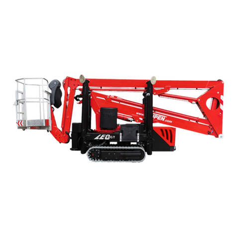
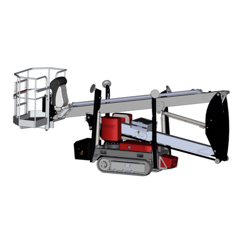
TEUPEN LEO 27T Operating instructions

Aerial access platform
Translation of the original operating
instructions
Serial number:
2017 Teupen GmbH
©

207/05/2018
Doku-BA T-Serie LEO27_35T_EN_00 201928
Manufacturer:
TEUPEN Maschinenbau GmbH
Marie-Curie-Straße 13
48599 Gronau, Germany
(: +49 (0) 2562 8161-0
6: +49 (0) 2562 8161-888
ü: www.teupen.com
Service:
(: +49 (0) 2562 8161-313
© TEUPEN Maschinenbau GmbH 2015
Manufacturer:
TEUPEN Maschinenbau GmbH
Marie-Curie-Straße 13
48599 Gronau, Germany
: +49 (0) 2562 8161-0
: +49 (0) 2562 8161-888
: info teupen.com
: www.teupen.com
Service:
: +49 (0) 2562 8161-313
: service teupen.com

Table of contents
07/05/2018 3
Table of contents
1 General .................................................................................................................................................................7
1.1 Information about these instructions............................................................................................................7
1.2 Explanation of symbols................................................................................................................................8
1.3 General symbol explanations ......................................................................................................................9
1.4 Limitation of liability....................................................................................................................................11
1.5 Copyright ...................................................................................................................................................11
1.6 Warranty conditions ...................................................................................................................................11
1.7 Notes regarding the warranty card ............................................................................................................11
1.8 Product trainings........................................................................................................................................12
2 EC Declaration of Conformity ..........................................................................................................................13
3 Safety..................................................................................................................................................................15
3.1 Basic hazards ............................................................................................................................................15
3.1.1 General hazards in the work station ............................................................................................ 15
3.1.2 Hazards due to electric energies ................................................................................................. 16
3.1.3 Hazards due to mechanical elements..........................................................................................18
3.1.4 Hazards due to hydraulic energies .............................................................................................. 19
3.1.5 Hazards due to high temperatures...............................................................................................20
3.1.6 Hazards due to chemicals............................................................................................................20
3.1.7 Hazards due to traffic and vehicles..............................................................................................22
3.2 Proper use .................................................................................................................................................23
3.3 Responsibility of the owner........................................................................................................................24
3.4 Personnel requirements.............................................................................................................................25
3.4.1 Qualification ................................................................................................................................. 25
3.4.2 Unauthorised Persons ................................................................................................................. 26
3.4.3 Training ........................................................................................................................................ 26
3.5 Personal protective equipment ..................................................................................................................27
3.6 Safety equipment.......................................................................................................................................28
3.6.1 Position of the safety equipment..................................................................................................28
3.6.2 Description of safety equipment...................................................................................................30
3.7 Symbols on the machine ...........................................................................................................................33
3.8 How to act in case of fire or accidents .......................................................................................................34
3.9 Environmental protection ...........................................................................................................................34
4 Technical data....................................................................................................................................................37
4.1 Dimensions ................................................................................................................................................37
4.2 Work diagrams...........................................................................................................................................38
4.2.1 Aerial lift platform work diagram...................................................................................................38
4.3 Power.........................................................................................................................................................38
4.4 Weights and loads .....................................................................................................................................39
4.5 Drives.........................................................................................................................................................39
4.5.1 Combustion engine ......................................................................................................................39
4.5.2 Electric motor ...............................................................................................................................39
4.6 Emission ....................................................................................................................................................39
4.7 Operating conditions..................................................................................................................................40
4.8 Consumables.............................................................................................................................................40
4.9 Filling quantities .........................................................................................................................................42

Table of contents
407/05/2018
4.10 Type plate ..................................................................................................................................................43
5 Construction and function................................................................................................................................45
5.1 Overview....................................................................................................................................................46
5.1.1 Brief description ...........................................................................................................................47
5.2 Assembly description.................................................................................................................................48
5.2.1 Crawler chassis............................................................................................................................48
5.2.2 Outriggers .................................................................................................................................... 48
5.2.3 Platform........................................................................................................................................ 49
5.2.4 Working basket ............................................................................................................................49
5.2.5 Movable basket boom.................................................................................................................. 49
5.2.6 Combustion engine ......................................................................................................................50
5.2.7 Electric motor ...............................................................................................................................50
5.3 Operating elements and displays ..............................................................................................................51
5.3.1 Outrigger latching.........................................................................................................................51
5.3.2 Control panel and radio control.................................................................................................... 53
5.3.3 Control panel adjustment (optinal) ...............................................................................................55
5.3.4 Combustion engine controller ......................................................................................................56
5.3.5 Control box control panels ...........................................................................................................57
5.3.6 Emergency control .......................................................................................................................58
5.4 Electrical connections ................................................................................................................................58
5.4.1 Feed ............................................................................................................................................. 58
5.4.2 Power sockets, working basket....................................................................................................59
5.5 Work areas and danger zones...................................................................................................................59
5.6 Accessories ...............................................................................................................................................60
5.6.1 Accessories (optional)..................................................................................................................60
5.6.2 Accessories (included) ................................................................................................................. 62
6 Transportation and storage..............................................................................................................................63
6.1 Safety instructions for transportation .........................................................................................................63
6.2 Inspection on receipt of delivery ................................................................................................................63
6.3 Attachment points ......................................................................................................................................64
6.4 Storage ......................................................................................................................................................66
6.5 Transportation on an auxiliary frame for trucks .........................................................................................67
6.5.1 Loading onto the truck ................................................................................................................. 67
6.5.2 Lashing ........................................................................................................................................ 68
7 Operation............................................................................................................................................................71
7.1 Safety instructions for operation ................................................................................................................71
7.2 Connecting the machine to the mains supply ............................................................................................71
7.3 Switching the machine on/off.....................................................................................................................73
7.3.1 Switching the radio control on/off................................................................................................. 73
7.3.2 Switching the machine on/off via the mains supply ..................................................................... 75
7.3.3 Switching the machine on/off using the combustion engine ........................................................ 75
7.4 Shutting down in case of emergency.........................................................................................................77
7.5 Principles of the graphic display screen ....................................................................................................78
7.5.1 Overview ...................................................................................................................................... 78
7.5.2 Possible assignment of the function keys .................................................................................... 78
7.5.3 Examples of the operating modes ............................................................................................... 79
7.5.4 Main menu ................................................................................................................................... 81
7.5.5 Machine data ............................................................................................................................... 81
7.5.6 Service hotline ............................................................................................................................. 82
7.5.7 Settings ........................................................................................................................................ 82
7.6 Driving the machine ...................................................................................................................................87
Table of contents
07/05/2018 5
7.6.1 Driving the machine using the controls ........................................................................................ 89
7.6.2 Driving the machine along a slope............................................................................................... 91
7.6.3 Driving the machine over ridges .................................................................................................. 92
7.6.4 Driving the machine up inclines ................................................................................................... 93
7.7 Adjusting the telescopic boom support ......................................................................................................94
7.7.1 Adjusting the telescopic boom support using the control box (optional) ...................................... 94
7.7.2 Adjusting the telescopic boom support using the radio control.................................................... 96
7.8 Moving the working basket into the work position (optional) .....................................................................98
7.8.1 Moving the working basket to the work position using the control box ........................................ 99
7.8.2 Moving the working basket to the work position using the radio control .................................... 100
7.9 Moving the bracing into the work position................................................................................................101
7.9.1 Adjusting a bracing .................................................................................................................... 102
7.9.2 Adjusting a bracing .................................................................................................................... 104
7.10 Operating the bracing ..............................................................................................................................106
7.10.1 Manual bracing .......................................................................................................................... 107
7.10.2 Automatic bracing ...................................................................................................................... 109
7.11 Adjusting and operating the outriggers for bracing ..................................................................................111
7.12 Crawler chassis, height- and width-adjustable ........................................................................................113
7.12.1 Hydraulic crawler adjustment ..................................................................................................... 113
7.12.2 Tips and recommendations for adjusting the crawler chassis hydraulically............................... 115
7.13 Operating the platform assembly.............................................................................................................116
7.14 Memory function ......................................................................................................................................120
7.14.1 Storing the working basket position ........................................................................................... 121
7.14.2 Moving the working basket into a stored position ...................................................................... 122
7.15 Moving the platform assembly into transport position..............................................................................123
7.15.1 Moving the platform assembly into transport position manually ................................................ 124
7.15.2 Moving the platform assembly to the transport position using the home function ..................... 125
7.16 Moving the bracing into the transport position .........................................................................................126
7.16.1 Moving the bracing into transport position manually .................................................................. 127
7.16.2 Moving the bracing into the transport position automatically ..................................................... 129
7.16.3 Moving the bracing to the transport position using the home function....................................... 130
7.17 Removing/mounting the working basket..................................................................................................131
7.17.1 Removing the working basket .................................................................................................... 131
7.17.2 Installing the working basket ...................................................................................................... 133
7.18 Lifting device............................................................................................................................................134
7.18.1 Mounting/removing the lifting device..........................................................................................135
7.18.2 Operating the lifting device ........................................................................................................ 137
7.19 Filling the fuel tank...................................................................................................................................139
7.20 Emergency operation...............................................................................................................................140
7.20.1 Platform assembly in emergency mode ..................................................................................... 140
7.20.2 Bracing in emergency mode ...................................................................................................... 144
7.20.3 Crawler chassis in emergency mode ......................................................................................... 147
7.21 Service mode...........................................................................................................................................153
7.21.1 Switching the machine on/off for service mode ......................................................................... 154
7.21.2 Platform assembly in service mode ........................................................................................... 156
7.21.3 Outrigger operation in service mode .......................................................................................... 159
7.21.4 Crawler chassis in service mode ............................................................................................... 162
7.22 12-V auxiliary drive ..................................................................................................................................166
7.23 Stowage space ........................................................................................................................................167
7.23.1 Opening the stowage space ...................................................................................................... 167
7.23.2 Locking the stowage space........................................................................................................168
7.24 Changing/charging the radio control’s batteries ......................................................................................169

Table of contents
607/05/2018
7.25 Checking the main battery’s capacity ......................................................................................................171
7.26 Charging the main battery .......................................................................................................................172
7.27 Jump-starting ...........................................................................................................................................174
7.28 Control panel adjustment (optional).........................................................................................................176
7.29 Locks .......................................................................................................................................................177
7.29.1 Resetting the combination on the shackle lock .......................................................................... 177
7.29.2 Combination lock on control panel ............................................................................................. 178
8 Maintenance.....................................................................................................................................................179
8.1 Safety instructions for maintenance.........................................................................................................179
8.2 Maintenance work....................................................................................................................................183
8.2.1 Cleaning the machine ................................................................................................................ 183
8.2.2 Tensioning the chain.................................................................................................................. 184
8.2.3 Checking/topping up hydraulic oil .............................................................................................. 186
8.2.4 Draining hydraulic oil..................................................................................................................187
8.2.5 Replace the hydraulic filter.........................................................................................................188
8.2.6 Checking the gear oil for the crawler chassis ............................................................................ 191
8.2.7 Lubricating the boom sections and ropes .................................................................................. 193
8.2.8 Lubricating the rotating assembly .............................................................................................. 195
8.2.9 Tightening torques for rotating assembly................................................................................... 196
8.2.10 Winter operation.........................................................................................................................196
8.2.11 Drive units overview ................................................................................................................... 197
8.3 Maintenance schedule.............................................................................................................................199
8.4 Maintenance work on the auxiliary frame for trucks ................................................................................202
8.4.1 Checking the lighting system ..................................................................................................... 203
8.4.2 Frame attachment...................................................................................................................... 203
8.4.3 Tightening torques ..................................................................................................................... 203
8.4.4 Checking attachment points.......................................................................................................204
8.5 Maintenance schedule, auxiliary frame for trucks....................................................................................205
9 Faults ................................................................................................................................................................207
9.1 Safety instructions for fault clearance......................................................................................................207
9.2 Fault table ................................................................................................................................................211
9.3 Error code list...........................................................................................................................................215
9.4 Changing fuses or circuit breakers ..........................................................................................................222
9.4.1 Fuse assignment........................................................................................................................223
9.5 Notes about the crawler track ..................................................................................................................227
9.6 Information messages .............................................................................................................................228
10 Disposal............................................................................................................................................................229
11 Appendix ..........................................................................................................................................................231
11.1 Circuit diagram.........................................................................................................................................233
11.2 Hydraulics diagram ..................................................................................................................................235
11.3 Adhesive label folder ...............................................................................................................................237
11.4 Drive units................................................................................................................................................258
11.4.1 Combustion engine (diesel) ....................................................................................................... 260
11.5 Radio control............................................................................................................................................282
11.6 RUD lifting accessories............................................................................................................................306
11.7 Accessories documentation.....................................................................................................................310
11.7.1 TEUPEN Operator Protection .................................................................................................... 312

General
07/05/2018 7
1 General
1.1 Information about these instructions
These instructions enable safe and efficient handling of the aerial lift platform (also
referred to below as the “machine”). The instructions are an integral part of the ma-
chine and must be kept in its immediate vicinity and remain accessible to the per-
sonnel at all times.
The trained personnel is required to have carefully read and understood these in-
structions prior to beginning any work. In addition to these instructions, also ob-
serve the supplier documentation included in the appendix. Working safely always
requires that the safety instructions, step-by-step instructions and notes contained
in these instructions are followed at all times.
In addition, observe the local accident prevention regulations and general safety in-
structions applicable at the machine’s deployment site.
Illustrations in these instructions are intended to convey a general understanding
and may differ from the actual equipment.

General
807/05/2018
1.2 Explanation of symbols
Safety instructions These instructions indicate safety instructions using symbols. The safety instruc-
tions begin with a signal word that indicates the extent of the respective risk.
DANGER
This combination of symbol and signal word indicates an immediate hazard that
will result in death or serious injury if not averted.
WARNING
This combination of symbol and signal word indicates a potential hazard that may
result in death or serious injury if not averted.
CAUTION
This combination of symbol and signal word indicates a potential hazard that may
result in slight or minor injury if not averted.
CAUTION
This combination of symbol and signal word indicates a potential hazard that may
result in damage to property or the environment if not averted.
Environmental protection
This combination of symbol and signal word indicates a potential environmental
hazard.
Tips and recommendations
NOTICE
This combination of symbol and signal word indicates useful information and re-
commendations that assist in using the machine efficiently and in avoiding faults.

General
07/05/2018 9
Specific notes on safety The following symbols are used in the safety instructions in order to highlight spe-
cific hazards:
DANGER
This combination of symbol and signal word indicates hazards resulting from elec-
trical current. Failure to observe the safety instructions may cause serious or fatal
injury.
Pictograms in these in-
structions
These instructions use the following pictograms and highlighting to indicate step-
by-step instructions, the results of actions, lists, references and other elements:
Pictogram Explanation
1. - Step-by-step instructions (numbered)
- - Results of individual steps
- References to chapters within these instructions or to other applic-
able documents
n- Indicates lists without a specifically required order
[ button ]Operating elements (e.g. buttons, switches), indicator elements (e.g.
telltale lamps)
1.3 General symbol explanations
Safety instructions
This warning symbol indicates electricity This warning symbol indicates a risk of crushed limbs
This warning symbol indicates hot sur-
faces
Prohibition signs
Do not use high-pressure jets Keep out of working basket when machine is driving
0-18
Working with the aerial lift prohibited for
under-18s
Observe aerial lift’s swivel range
Do not work on live parts
Max. 400N
Observe lateral force
Keep loads level when lifting
Max. 12,5 m/sek.
(6Bft.)
1.
2.
Observe wind speed
Do not climb onto working basket’s railing

General
10 07/05/2018
Mandatory instruction
signs
Wear foot protection Wear a welding mask
Wear protective clothing Earth before using
Wear hand protection Wear hearing protection
Wear safety harness Wash your hands
Wear safety goggles Apply skin protection
Wear protective headgear Disconnect from mains
Wear breather mask Observe operating instructions
Wear facemask Wear high-visibility jacket

General
07/05/2018 11
1.4 Limitation of liability
All data and notes in these operating instructions have been compiled in compli-
ance with the applicable standards and regulations and based on the technological
state of the art as well as on our many years of knowledge and experience.
The manufacturer shall accept no liability for damage caused by:
nFailure to observe these instructions
nImproper use
nDeployment of untrained personnel
nImproper assembly, commissioning, operation or maintenance of the machine
nOperation of the machine with faulty safety equipment or improperly attached
or inoperative safety devices and protective barriers
nUnauthorised conversion
nTechnical modifications
nInsufficient monitoring of the machine parts subject to wear
nImproperly performed repairs
nUse of unapproved spare parts
nUnauthorised modification of a component’s software
nDisasters caused by foreign bodies or acts of God
The actual scope of supply may differ from that described and shown in these in-
structions in the case of special designs, where additional options have been
ordered or as a result of the latest technical changes. The obligations entered into
as part of the supply contract, the general terms and conditions and the manufac-
turer’s delivery conditions, and the legal provisions as applicable at the time of con-
cluding the contract shall apply.
1.5 Copyright
The content of these instructions is subject to copyright.
Its use is permitted within the scope of machine operation. Any use beyond this
(electronic or manual), in whole or in part, including translation into another lan-
guage, requires the manufacturer’s written consent.
All rights to these instructions held by Teupen Maschinenbau GmbH.
1.6 Warranty conditions
The warranty terms are included in the manufacturer’s
general terms and conditions.
1.7 Notes regarding the warranty card
To ensure that any warranty claims can be smoothly processed among customer,
service partner and Teupen, it is essential that the warranty card included at the
beginning of the machine record be filled in and sent back to Teupen immediately

General
12 07/05/2018
after the machine has been handed over the owner. If the warranty card is not filled
in correctly, we will not be able to process any warranty claims as important data
required for processing will not be available to us.
Please send the warranty card to:
Teupen Maschinenbau GmbH
Service Point
Marie-Curie-Straße 13
48599 Gronau, Germany
Example of correctly filled
in warranty card:
Die Gewährleistungskarte innerhalb von sechs Monaten nach der Übergabe ausfüllen und an die TEUPEN Maschinenbau GmbH senden.
Sie unterstützen damit den optimalen Service von TEUPEN. Danke.
Gewährleistungskarte / Warranty card
Maschinentyp / Machine type Seriennummer / Serialnumber Übernahmedatum / Date of handover
Firma / Company
Adresse / Address
Telefon, E-Mail / Phone, E-Mail
Ansprechpartner / Contact person
Händler / Distributer
Unterschrift des Händlers / Distributer's signature Unterschrift des Betreibers / Owner's signature
Standort der Maschine / Location of machine
Please fill out and return this warranty card within six month after handover to TEUPEN Maschinenbau GmbH.
You will support TEUPEN service team in better performing. Thank you.
300440
TL95SJ 10000000 08.12.2017
Lawnscape Garden Maintenance
12345 Peterson Street / Hopetown
864 - 208 - 9759
John Doe
TEUPEN Maschinenbau GmbH
Jane Doe John Doe
Fig.1
1.8 Product trainings
Besides comprehensive training on the machine, we offer a broad range of training
courses in the fields of operation, maintenance and application.
For further details, visit http://www.teupen.com.

EC Declaration of Conformity
07/05/2018 13
2 EC Declaration of Conformity
EC Declaration of Conformity as per EC Machinery Directive 2006/42/EC of 2006-05-17, appendix ll A
We hereby declare that the following machinery satisfies the essential health and safety requirements of the Ma-
chinery Directive, including the changes in force at the time of the declaration conform by its design, construction
and model type produced by us. This declaration will be rendered null and void in case of any change made to the
machine without consulting with us.
Manufacturer: Teupen Maschinenbau GmbH
Marie-Curie-Straße 13
48599 Gronau, Germany
Machine designation: Mobile aerial lift platform
Machine type: LEO27T LEO31T LEO35T
Test number: 340697600 340644700-2 340764500
Applicable EC directives: EC Machinery Directive 2006/42/EC
EC Low Voltage Directive 2014/35/EU
EC Electromagnetic Compatibility Directive 2014/30/EU
EC Directive 2000/14/EC
Applicable harmonised standards: EN 280:2013
EN ISO
12100-1/-2:2003
Safety of machinery - Basic terms, general principles
for design
EN ISO 13850 Safety of machinery - Emergency Stop, general prin-
ciples for design
EN 60204-1:2006 Safety of machinery - Electrical equipment of ma-
chinery - Part 1: General requirements
Applicable national standards and
technical specifications:
BGG 945
Appointed agent for the compilation of
the technical documents:
TEUPEN Maschinenbau GmbH
Marie-Curie-Straße 13
48599 Gronau, Germany
Appointed office for type approval pro-
cedures:
DEKRA Certification GmbH
Handwerkstraße 15
D-70565 Stuttgart
Reg. No. 0124
Gronau, ________________
Tobias Ritzenhöfer (Technical Director)

Safety
14 07/05/2018

Safety
07/05/2018 15
3 Safety
This section provides an overview of all key safety aspects for protecting people
and for safe and fault-free operation. Additional specific safety instructions are in-
cluded in the sections detailing the individual service life phases.
3.1 Basic hazards
The following section indicates remaining risks which may arise in connection with
the machine even when it is used for its proper use.
In order to reduce the risks of personal injury and material damage and to prevent
hazardous situations, adhere to the safety instructions listed here and the safety in-
structions in the other sections of these operating instructions.
3.1.1 General hazards in the work station
Swivelling aerial access
platform
WARNING
Risk to life due to swivelling aerial access platform!
During operation, the aerial access platform can swivel out. This can cause severe
injuries or even death.
– Never step under or into the swivel range of the aerial access platform.
– Only move the aerial access platform under supervision.
– Always operate the aerial access platform as a pair, with the help of a second
person.
– Always wear personal protective equipment.
Work on higher up situated
places
WARNING
Risk of falling!
During work on higher up situated places, there is a risk of falling. This can cause
serious or even fatal injuries.
– Always wear full body harnesses (acc. to EN361) when in the working basket
and do not swing or move abruptly.
– Do not climb onto the safety fence around the basket.
– Make sure that the machine is set up properly and holds securely.
– Make sure that when moving the working basket, no body parts are crushed,
e.g. against a wall.
– At wind speeds above 12.5m/s (wind strength 6 Bft), stop work immediately.
– Always wear personal protective equipment.

Safety
16 07/05/2018
Exhaust gases
WARNING
Risk to life from poisoning or suffocation due to exhaust gases!
When inhaled, exhaust gases can lead to suffocation and cause severe poisoning
as well a illness of the respiratory system.
– Always ensure fresh air supply when working on the machine in diesel engine
mode.
– Any person inhaling exhaust gases must be provided with fresh air immedi-
ately and checked by a physician.
3.1.2 Hazards due to electric energies
Electrical current
DANGER
Risk of fatal injury due to electrical current!
There is a direct risk of fatal injury due to electric shock in case of contact with live
parts. Damage to the insulation or individual components may represent a risk of
fatal injury.
– Do not work on or near high-voltage lines.
– Only have qualified electricians perform work on the electrical system.
– In case of damage to the insulation, switch off the voltage supply immediately
and have the machine repaired.
– Never bypass or disable any fuses or circuit breakers. When changing fuses
or circuit breakers, make sure that the ampere rating is correct.
– Keep moisture away from parts which are live with voltage. It may cause a
short-circuit.
– Adhere to cable strengths based on "Cable length". Electric motor.
– Lay (extension) cables so that they cannot be driven over, they do not come
into contact with liquids, they are not sharply nicked or otherwise stressed.
– Keep outlet easily accessible at all times.
– Before performing work on live parts, pull the mains plug.

Safety
07/05/2018 17
Batteries
WARNING
Risk of injury due to improper handling of batteries!
Wrong handling of batteries poses the risk that the batteries burst or that noxious li-
quid leaks from the batteries. The liquid may cause skin burns when in contact or
severe poisoning if swallowed and can cause blindness when contact with the
eyes.
– Never short-circuit the contacts (plus and minus pole) of the battery.
– Never use or store batteries at locations with potentially explosive atmosphere
or where high temperatures occur.
– Never try to weld, repair or change batteries in any manner or take it apart or
retrofit.
– Always protect battery from unauthorized access.
– To prevent fire, overheating, explosion or leakage of fluid never expose the
batteries to severe vibration, high weight bearing or other harmful effects.
Leaking and spilled liquid can ignite.
– Avoid contact with spilled liquid.
Measures after contact with battery fluid:
nWash skin with water and soap after contact.
nImmediately flush out eyes and underneath eye lid for 15 minutes with clear
water. When doing so, point mild water jet directly into the eye, do not rub
eyes, immediately contact a physician.

Safety
18 07/05/2018
3.1.3 Hazards due to mechanical elements
Falling parts
WARNING
Risk of injury due to falling parts!
During operation, material can fall down uncontrolled and cause severe injuries.
– Make others aware of the danger zone and block off the area.
– Do not enter the danger zone during normal operation.
– Never place objects on the working basket safety fence.
Outriggers and arms
DANGER
Risk of crushing on outriggers and arms!
When bracing or swivelling the machine, there is a risk of crushing.
– Make sure that when bracing, no persons, supply lines or other objects are in
the area around the supports.
– Ensure that no persons are within the danger zone when swivelling the ma-
chine.
– Make sure that no persons are in the danger zone when moving into transport
position.
Insufficient stability
WARNING
Risk of injury due to insufficient stability!
Without sufficient stability, there is a risk of the machine toppling. This can cause
serious or even fatal injuries.
– Make sure that the ground has sufficient load capacity.
– Do not exceed the maximum slope.

Safety
07/05/2018 19
Chain drive
WARNING
Risk to life due to pulling in and pinching off body parts on the
chain drive!
Running chains and rotating chain wheels can pull in pieces of clothing as well as
body parts and thus cause severe to fatal injuries.
– During operation, do not reach into running chains or chain wheels.
– Keep chain drives inaccessible during operation. Do not open any covers.
– While in the danger zone, wear closely-fitting protective clothing with low tear
strength.
– Before all work on chains or chain wheels, switch the machine off and secure
against restart. Wait until all components have come to a standstill.
– During operation, maintain a sufficient safety distance.
– Pay attention to the change of direction.
WARNING
Risk of injury due to driving over body parts!
With the crawler chassis, there is a risk of pinching off body parts and thus causing
severe to fatal injuries.
– During operation, do not reach into running chains or chain wheels.
– During operation, maintain a sufficient safety distance.
– Pay attention to the change of direction.
– Do not drive over power lines.
3.1.4 Hazards due to hydraulic energies
Hydraulics
WARNING
Risk of fatal injury posed by hydraulic energies!
Hydraulic powered moving parts can cause serious injuries.
– Work on hydraulic system may only be carried out by hydraulic experts.
– Before starting any work de depressurise the hydraulic system.
– Never reach into moving parts or work on moving parts during operation.
– Do not open covers during operation.
– While in the danger zone, wear closely-fitting protective clothing with low tear
strength.

Safety
20 07/05/2018
3.1.5 Hazards due to high temperatures
Hot surfaces
WARNING
Risk of injury due to hot surface!
Surfaces of motor components can heat up considerably during operation. Skin
contact with hot surfaces causes severe burns to the skin.
– Avoid contact with hot motor components such as exhaust system, radiator,
hoses and engine block.
– Check before all work on engine components, as to whether these are hot. Al-
low them to cool down if necessary.
3.1.6 Hazards due to chemicals
Anti-freeze agents
WARNING
Health hazard due to anti-freeze agents!
The coolant of the diesel engine consists of a water anti-freeze agent mixture.
Upon body contact, ingestion or inhalation of areosoles, anti-freeze agents can
lead to serious health problems.
– Avoid contact with anti-freeze agents.
– Do not eat, drink or smoke when handling anti-freeze agents. Prior to breaks
and completion of work, wash hands.
– Wear protective gloves when working with anti-freeze agents.
Measures after contact with anti-freeze agents:
nWash skin with lots of water after contact.
nRinse eyes thoroughly with water for at least 15 minutes after contact and con-
sult a physician.
nRinse out mouth after ingesting and drink lots of water thereafter. Consult a
physician.
nAfter aerosol inhalation go outdoors for fresh air.
Motor oil
WARNING
Risk of injury due to motor oil!
Motor oil contains toxic substances that can trigger inflammation and are carcino-
genic.
– Prevent skin contact with motor oil.
– After accidental skin contact, immediately wash your hands with soap. Do not
use gasoline, solvent or other chemical cleaners.
This manual suits for next models
2
Table of contents
Other TEUPEN Boom Lift manuals
Popular Boom Lift manuals by other brands

CMC
CMC S15 manual

NIFTYLIFT
NIFTYLIFT nifty TM Series Operating and safety instructions

Multitel Pagliero
Multitel Pagliero 160 ALU operating instructions

JLG
JLG 600S Operation and safety manual

TIGIEFFE
TIGIEFFE AIRO A Series user manual

Oshkosh Corporation
Oshkosh Corporation JLG H800AJ Operation and safety manual