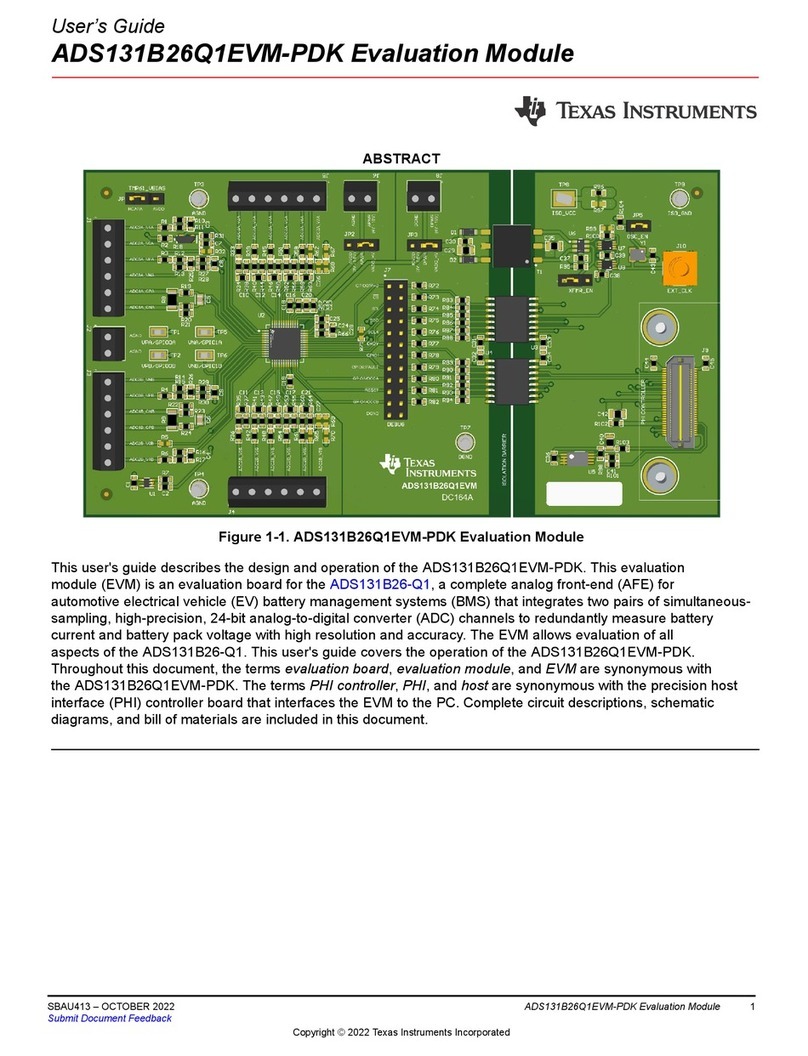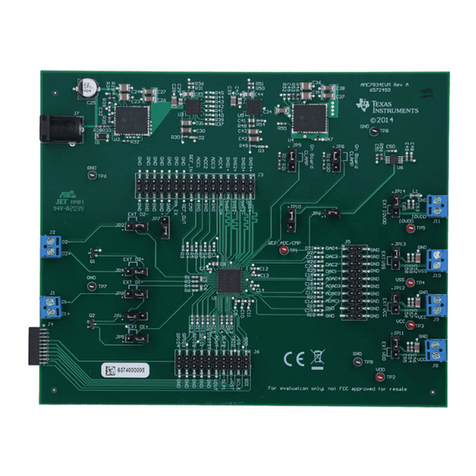
User’s Guide
DAC12DL3200 Evaluation Module
ABSTRACT
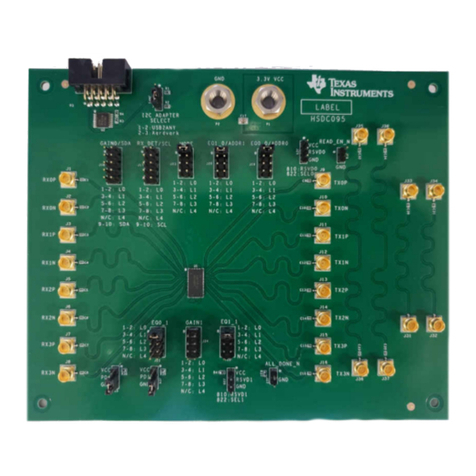
The DAC12DL3200 evaluation module (EVM) is used to evaluate the DAC12DL3200 digital-to-analog converter
(DAC) from Texas Instruments. Throughout this document, the terms evaluation board, evaluation module, and
EVM are synonymous with the DAC12DL3200EVM.
Table of Contents
1 Introduction.............................................................................................................................................................................2
1.1 Low Latency Evaluation of Receive and Transmit............................................................................................................. 3
1.2 Related Documentation......................................................................................................................................................4
2 Equipment............................................................................................................................................................................... 4
2.1 Evaluation Board Feature Identification Summary.............................................................................................................4
2.2 Required Equipment.......................................................................................................................................................... 5
3 Setup Procedure..................................................................................................................................................................... 6
3.1 Install the High Speed Data Converter (HSDC) Pro Software........................................................................................... 7
3.2 Install the Configuration GUI Software...............................................................................................................................7
3.3 Connect the DAC12DL3200EVM and TSW14DL3200EVM.............................................................................................. 7
3.4 Connect the Power Supplies to the Boards (Power Off).................................................................................................... 7
3.5 Connect the Signal Generators to the EVM (*RF Outputs Disabled Until Directed).......................................................... 8
3.6 Turn On the TSW14DL3200EVM 12-V Power and Connect to the PC..............................................................................8
3.7 Turn On the DAC12DL3200EVM 5-V Power Supply and Connect to the PC.................................................................... 8
3.8 Turn On the Signal Generator RF Outputs.........................................................................................................................8
3.9 Open the DAC12DL3200EVM GUI and Program the DAC and Clocks for Single Channel, NRZ Mode 2 Operation....... 9
3.10 Open the HSDC Software and Load the FPGA Image to the TSW14DL3200EVM....................................................... 11
3.11 DxSTRB Timing Adjustment...........................................................................................................................................14
4 Other Modes of Operation....................................................................................................................................................17
4.1 Single-Channel RF Mode 2 (2nd Nyquist Zone).............................................................................................................. 17
4.2 Dual-Channel Output Mode 0.......................................................................................................................................... 17
4.3 Dual Channel Mode1 Setup............................................................................................................................................. 18
4.4 Dual-Channel 2xRF Mode 0 DAC Setup..........................................................................................................................18
4.5 Direct Digital Synthesis Mode.......................................................................................................................................... 18
5 Register Log File...................................................................................................................................................................21
6 Device Configuration............................................................................................................................................................22
6.1 Tab Organization.............................................................................................................................................................. 22
6.2 Low-Level Control............................................................................................................................................................ 22
A Troubleshooting the DAC12DL3200EVM........................................................................................................................... 24
B DAC12DL3200EVM Onboard Clocking Configuration...................................................................................................... 25
List of Figures
Figure 1-1. DAC12DL3200EVM.................................................................................................................................................. 2
Figure 1-2. Low Latency LVDS-Based ADC Receiver and DAC Transmitter.............................................................................. 3
Figure 1-3. Low Latency ADC EVM, Capture Card and Pattern Generator, and DAC EVM....................................................... 3
Figure 2-1. DAC12DL3200EVM Features................................................................................................................................... 4
Figure 3-1. EVM Test Setup.........................................................................................................................................................6
Figure 3-2. Configuration GUI: LMK04828 Tab........................................................................................................................... 9
Figure 3-3. Low Level View Tab.................................................................................................................................................10
Figure 3-4. Selecting Configuration File.................................................................................................................................... 10
Figure 3-5. No Firmware Loaded............................................................................................................................................... 11
Figure 3-6. Selecting DAC Mode 2............................................................................................................................................ 12
Figure 3-7. HSDC Pro GUI Setup..............................................................................................................................................13
Figure 3-8. IO Delay.................................................................................................................................................................. 14
www.ti.com Table of Contents
SBAU374 – MAY 2021
Submit Document Feedback
DAC12DL3200 Evaluation Module 1
Copyright © 2021 Texas Instruments Incorporated
