2.11 Quick-Start Guide (SMBus Slave Mode)........................................................................................................................ 11
3 Schematics............................................................................................................................................................................13
4 PCB Layouts..........................................................................................................................................................................20
5 Bill of Materials..................................................................................................................................................................... 23
List of Figures
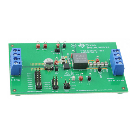
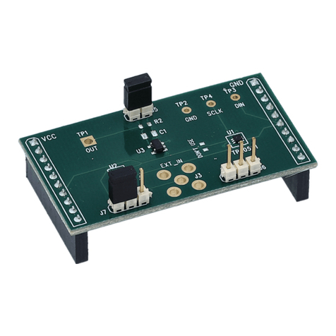
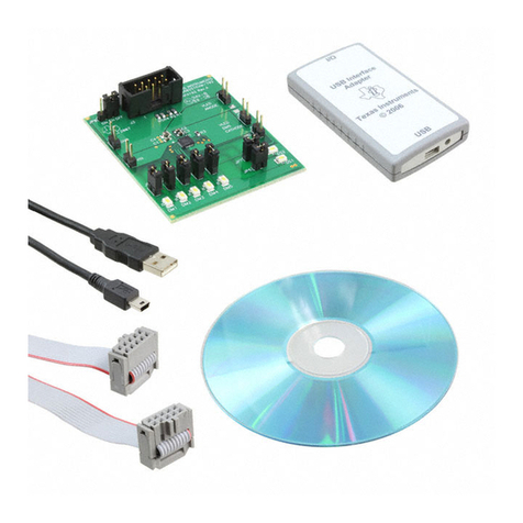
Figure 1-1. DS320PR412-421EVM............................................................................................................................................. 1
Figure 2-1. SigCon Architect DS320PR412-421 High Level Page............................................................................................ 12
Figure 3-1. DS320PR412.......................................................................................................................................................... 13
Figure 3-2. DS320PR421.......................................................................................................................................................... 14
Figure 3-3. Configuration Headers............................................................................................................................................ 15
Figure 3-4. I2C Adapter Selection............................................................................................................................................. 15
Figure 3-5. Power...................................................................................................................................................................... 16
Figure 3-6. EDGE Finger........................................................................................................................................................... 17
Figure 3-7. PCIe Clock.............................................................................................................................................................. 18
Figure 3-8. PCIe x8 Connector A...............................................................................................................................................18
Figure 3-9. PCIe x16 Connector B.............................................................................................................................................19
Figure 4-1. Top Layer.................................................................................................................................................................20
Figure 4-2. Layer 2.................................................................................................................................................................... 20
Figure 4-3. Layer 3.................................................................................................................................................................... 21
Figure 4-4. Layer 4.................................................................................................................................................................... 21
Figure 4-5. Layer 5.................................................................................................................................................................... 22
Figure 4-6. Bottom Layer........................................................................................................................................................... 22
List of Tables
Table 2-1. Five-Level Control Pin Settings...................................................................................................................................4
Table 2-2. Modes of Operation.................................................................................................................................................... 4
Table 2-3. Redriver-Mux SMBus Address Map............................................................................................................................4
Table 2-4. Equalization Control Settings......................................................................................................................................5
Table 2-5. Rx Detect Control Pin Settings................................................................................................................................... 6
Table 2-6. GAIN Control...............................................................................................................................................................6
Table 2-7. EVM Global Controls.................................................................................................................................................. 7
Table 2-8. EVM Downstream Devices Controls...........................................................................................................................8
Table 2-9. EVM Upstream Devices Controls............................................................................................................................... 9
Table 2-10. Pin Mode Shunt Configuration................................................................................................................................ 10
Table 2-11. SMBus/I2C Mode Shunt Configuration....................................................................................................................11
Table 5-1. DS320PR412-421 Bill of Materials........................................................................................................................... 23
Trademarks
All trademarks are the property of their respective owners.
Trademarks www.ti.com
2DS320PR412-421EVM User's Guide SNLU301 – NOVEMBER 2021
Submit Document Feedback
Copyright © 2021 Texas Instruments Incorporated
