1
SLAU812–July 2019
Submit Documentation Feedback Copyright © 2019, Texas Instruments Incorporated
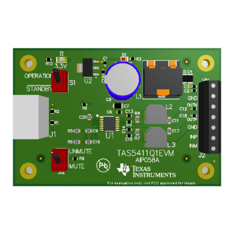
TAS2564YBGEVM-DC User's Guide
User's Guide
SLAU812–July 2019
TAS2564YBGEVM-DC User's Guide
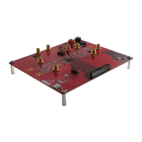
The TAS2564YBGEVM-DC is designed to demonstrate the performance of TAS2564 in a stereo
configuration. The design utilizes the PPC3-EVM-MB hardware to provide an interface and supply
voltages to the EVM. TAS2564 is a mono, digital-input, Class-D audio amplifier optimized for efficiently
driving high peak power into small loudspeaker applications. The Class-D amplifier is capable of delivering
8 W of peak power into a 4 Ωload at a battery voltage of 3.6 V. Integrated speaker voltage and current
sense provides real time monitoring of loud speakers. Up to four devise can share a common bus via
I2S/TDM + I2C interfaces.
Contents
1 Export Control Notice ....................................................................................................... 3
2 Description ................................................................................................................... 3
3 Specifications ................................................................................................................ 3
4 Software ...................................................................................................................... 3
5 Device Configuration ....................................................................................................... 4
6 3 Wire Speaker Connection ................................................................................................ 9
7 Digital Audio Interfaces ................................................................................................... 10
8 EVM Schematics .......................................................................................................... 11
9 EVM Layer Plots ........................................................................................................... 12
10 Bill of Materials ............................................................................................................. 15
List of Figures
1 Requesting PPC3 Access ................................................................................................. 4
2 Default Jumper Settings .................................................................................................... 4
3 Address Select............................................................................................................... 5
4 Mono Setup................................................................................................................... 5
5 Windows Playback Devices ................................................................................................ 6
6 Texas Instruments USB Audio Device Control Panel................................................................... 6
7 Windows Playback device Sample Rate ................................................................................. 7
8 Stereo Setup ................................................................................................................. 7
9 Windows Playback Devices ................................................................................................ 8
10 Texas Instruments USB Audio Device Control Panel................................................................... 8
11 Windows Playback device Sample Rate ................................................................................. 9
12 ................................................................................................................................ 10
13 TAS2564 Three Wire connection ........................................................................................ 10
14 EVM Schematic ............................................................................................................ 11
15 TAS2564YBGEVM-DC Top Silk Screen ............................................................................... 12
16 TAS2564YBGEVM-DC Top Solder Mask .............................................................................. 12
17 TAS2564YBGEVM-DC Top Copper .................................................................................... 12
18 TAS2564YBGEVM-DC Copper Layer 2 ................................................................................ 12
19 TAS2564YBGEVM-DC Copper Layer 3 ................................................................................ 12
20 TAS2564YBGEVM-DC Copper Layer 4 ................................................................................ 12
21 TAS2564YBGEVM-DC Copper Layer 5 ................................................................................ 13
22 TAS2564YBGEVM-DC Bottom Copper ................................................................................ 13
