User’s Guide
TPS23755EVM-894 Evaluation Module
ABSTRACT
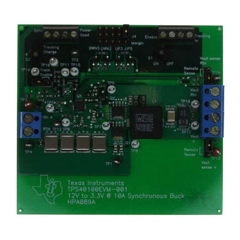
This user’s guide describes the TPS23755 evaluation module (EVM). The TPS23755 evaluation module
(TPS23755EVM-894) contains evaluation and reference circuitry for the TPS23755 device. The TPS23755
device is an IEEE 802.3at Type 1 compliant, powered-device (PD) controller and power supply controller
optimized for primary side regulation flyback converter topologies. TPS23755EVM-894 is targeted for a 12-V
diode-rectified high efficiency 13-W PD solution.
Table of Contents
1 Introduction.............................................................................................................................................................................2
1.1 Features............................................................................................................................................................................. 2
1.2 Applications........................................................................................................................................................................2
2 Electrical Specifications........................................................................................................................................................ 2
3 Description.............................................................................................................................................................................. 2
4 Schematic................................................................................................................................................................................4
5 General Configuration and Description................................................................................................................................5
5.1 Physical Access................................................................................................................................................................. 5
6 TPS23755EVM-894 Performance Data.................................................................................................................................. 5
6.1 Startup to PSE and DCDC Startup.................................................................................................................................... 5
6.2 Transient Response........................................................................................................................................................... 6
6.3 Efficiency............................................................................................................................................................................8
6.4 Load Regulation................................................................................................................................................................. 8
6.5 Recovery from VOUT Short............................................................................................................................................... 9
6.6 Slew Rate Adjust................................................................................................................................................................9
7 EVM Assembly Drawings and Layout Guidelines............................................................................................................. 12
7.1 PCB Drawings..................................................................................................................................................................12
7.2 Layout Guidelines............................................................................................................................................................ 16
7.3 EMI Containment............................................................................................................................................................. 17
8 Bill of Materials..................................................................................................................................................................... 18
Revision History.......................................................................................................................................................................23
List of Figures
Figure 4-1. TPS23755EVM-894 Schematic.................................................................................................................................4
Figure 6-1. Startup Response When Connected to a PoE PSE (TPS23861) and DCDC Startup.............................................. 6
Figure 6-2. Transient Response from 100 mA to 1 A for a 48-V Input.........................................................................................7
Figure 6-3. Efficiency of the TPS23755EVM-894........................................................................................................................ 8
Figure 6-4. TPS23755EVM-894 Load Regulation....................................................................................................................... 8
Figure 6-5. DCDC Recovery From Output Short......................................................................................................................... 9
Figure 6-6. SRF = 0 Ω..................................................................................................................................................................9
Figure 6-7. SRF = 100 Ω............................................................................................................................................................10
Figure 6-8. SRR = 0 Ω............................................................................................................................................................... 10
Figure 6-9. SRR = 15 Ω............................................................................................................................................................. 11
Figure 7-1. Top-Side Component Placement.............................................................................................................................12
Figure 7-2. Layer 2 Routing....................................................................................................................................................... 13
Figure 7-3. Layer 3 Routing....................................................................................................................................................... 14
Figure 7-4. Bottom-Side Routing............................................................................................................................................... 15
List of Tables
Table 2-1. TPS23755EVM-894 Electrical and Performance Specifications at 25°C....................................................................2
Table 5-1. Connector Functionality.............................................................................................................................................. 5
www.ti.com Table of Contents
SLVUBG8A – JULY 2018 – REVISED DECEMBER 2020
Submit Document Feedback
TPS23755EVM-894 Evaluation Module 1
Copyright © 2020 Texas Instruments Incorporated
