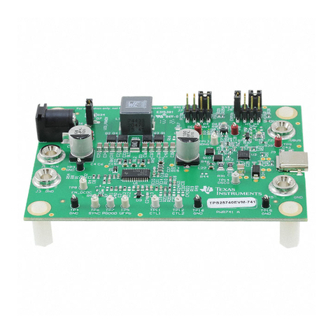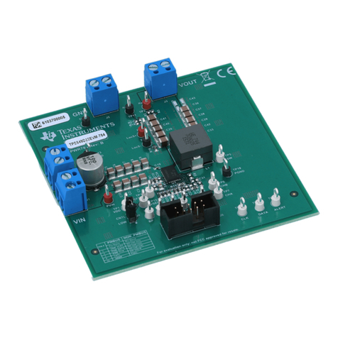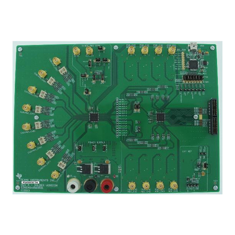
Description
www.ti.com
9 Bill of Materials ............................................................................................................. 25
List of Figures
1 TPS53819AEVM-123 Schematic ......................................................................................... 4
2 Tip and Barrel Measurement for VOUT Ripple............................................................................ 6
3 Probe with Short Ground Lead for VOUT Ripple Across C14........................................................... 6
4 TPS53819AEVM-123 Recommended Test Set Up .................................................................... 7
5 Selection of Device Scan Options ........................................................................................ 9
6 TPS53819A GUI Configure General Tab................................................................................ 9
7 TPS53819A GUI Configure, All Config Tab............................................................................ 10
8 TPS53819A GUI Status .................................................................................................. 10
9 TPS53819AEVM-123 Efficiency......................................................................................... 12
10 TPS53819AEVM-123 Load Regulation................................................................................. 12
11 TPS53819AEVM-123 Line Regulation.................................................................................. 13
12 TPS53819AEVM-123 fSW Versus Load ................................................................................. 13
13 TPS53819AEVM-123 Loop Response Gain and Phase ............................................................. 14
14 TPS53819AEVM-123 Load Transient, 12 VIN, 0–15-A Eco-mode ................................................. 14
15 TPS53819AEVM-123 Load Transient, 12 VIN, 0–15-A FCCM ...................................................... 15
16 TPS53819AEVM-123 Output Ripple, 12 VIN, 25 A.................................................................... 15
17 TPS53819AEVM-123 Output Ripple, 12 VIN, 1-A Load Eco-mode ................................................. 16
18 TPS53819AEVM-123 Switching Node, 12-VIN, 25-A Load Full Bandwidth ........................................ 16
19 TPS53819AEVM-123 Enable Turn on Waveform, 12-VIN, 1-ΩLoad ............................................... 17
20 TPS53819AEVM-123 VIN Turn on Waveform, 12-VIN, 1-ΩLoad .................................................... 17
21 TPS53819AEVM-123 Enable Turn off Waveform, 12 VIN, 1-ΩLoad ............................................... 18
22 TPS53819AEVM-123 VIN Turn off Waveform, 12 VIN, 1-ΩLoad .................................................... 18
23 TPS53819AEVM-123 Enable Turn on waveform, 12 VIN, 1-ΩLoad, 1-V Pre-bias ............................... 19
24 TPS53819AEVM-123 Top Board, 12 VIN, 25-A Fan .................................................................. 19
25 TPS53819AEVM-123 Bottom Board, 12 VIN, 25-A Fan .............................................................. 20
26 TPS53819AEVM-123 Top Layer Assembly Drawing (Top view) ................................................... 21
27 TPS53819AEVM-123 Bottom Layer Assembly Drawing (Bottom view)............................................ 21
28 TPS53819AEVM-123 Top Copper (Top view)......................................................................... 22
29 TPS53819AEVM-123 Internal Layer 1 (Top view).................................................................... 22
30 TPS53819AEVM-123 Internal Layer 3 (Top view).................................................................... 23
31 TPS53819AEVM-123 Internal Layer 4 (Top view).................................................................... 23
32 TPS53819AEVM-123 Internal Layer 5 (Top view).................................................................... 24
33 TPS53819AEVM-123 Bottom Copper (Top view)..................................................................... 24
List of Tables
1 TPS53819AEVM-123 Electrical Performance Specifications ......................................................... 3
2 The Functions of Each Test Points....................................................................................... 8
3 Enable Selection ............................................................................................................ 8
4 TPS53819AEVM-123 List of Materials ................................................................................. 25
1 Description
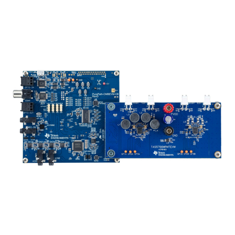
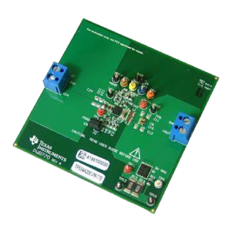
The TPS53819AEVM-123 is designed to use a regulated 12-V bus to produce a regulated 1.2-V output at
up to 25 A of load current. The TPS53819AEVM-123 is designed to demonstrate the TPS53819A in a
typical low voltage application while providing a number of test points to evaluate the performance of the
TPS53819A.
2Using the TPS53819AEVM-123 Wide Input Voltage, Eco-mode, Single SLVU719A–May 2012–Revised December 2012
Synchronous Step-Down Controller with PMBus™ Submit Documentation Feedback
Copyright © 2012, Texas Instruments Incorporated
