User’s Guide
Using the UCC14131EVM-070 for Biasing GaN and Gate
Driver ICs in Automotive and Industrial Applications
ABSTRACT
This user’s guide provides a description and instructions for use of the UCC14131EVM-070 to evaluate the
UCC14131-Q1; a high frequency, integrated transformer, DC-DC converter module from Texas Instruments. This
EVM allows designers to quickly and efficiently evaluate the UCC14131-Q1 for use in automotive or industrial
applications requiring gate driver IC bias power as high as 1.5 W, meeting up to 5 kVRMS isolation.
Table of Contents
1 Introduction.............................................................................................................................................................................3
1.1 Pin Configuration and Functions........................................................................................................................................ 3
2 Description.............................................................................................................................................................................. 5
2.1 EVM Electrical Performance Specifications....................................................................................................................... 6
3 Schematic................................................................................................................................................................................7
4 EVM Setup and Operation......................................................................................................................................................8
4.1 Recommended Test Equipment......................................................................................................................................... 8
4.2 External Connections for Easy Evaluation......................................................................................................................... 8
4.3 Powering the EVM............................................................................................................................................................. 9
4.4 EVM Test Points.................................................................................................................................................................9
4.5 Probing the EVM.............................................................................................................................................................. 11
5 Performance Data................................................................................................................................................................. 12
5.1 Efficiency Data................................................................................................................................................................. 12
5.2 Regulation Data............................................................................................................................................................... 14
5.3 Steady State Input Current...............................................................................................................................................15
5.4 Start-Up Waveforms.........................................................................................................................................................15
5.5 Inrush Current.................................................................................................................................................................. 18
5.6 AC Ripple Voltage............................................................................................................................................................ 20
5.7 EN and Timing..................................................................................................................................................................22
5.8 RLIM.................................................................................................................................................................................22
5.9 Shutdown......................................................................................................................................................................... 24
5.10 Thermal Performance.................................................................................................................................................... 25
6 Assembly and Printed Circuit Board (PCB) Layers...........................................................................................................26
7 Bill of Materials (BOM)..........................................................................................................................................................30
List of Figures
Figure 1-1. DWN Package, 36-Pin SSOP (Top View)..................................................................................................................3
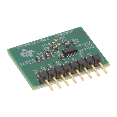
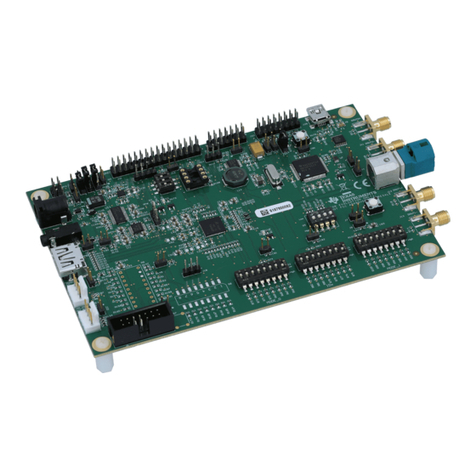
Figure 2-1. UCC14131EVM-070 (Top View)................................................................................................................................5
Figure 2-2. UCC14141EVM-070 (Bottom View).......................................................................................................................... 5
Figure 3-1. UCC14131EVM-070 Schematic Diagram................................................................................................................. 7
Figure 4-1. Typical Efficiency Measurement Setup......................................................................................................................8
Figure 4-2. UCC14131EVM-070, PCB Scope Probe Test Points.............................................................................................. 11
Figure 5-1. Measured Efficiency, VDD-VEE = 12-V Loading Only.............................................................................................12
Figure 5-2. Regulation vs Power, VDD-VEE Loading Only....................................................................................................... 14
Figure 5-3. Regulation vs Current, VDD-VEE Loading Only..................................................................................................... 14
Figure 5-4. Input Current vs Power, VDD-VEE Loading Only....................................................................................................15
Figure 5-5. Start-up 1: VIN = 12 V, IVDD = 0 mA, I[+5V] = 0 mA.................................................................................................. 15
Figure 5-6. Start-up 2: VIN = 12 V, IVDD = 130 mA, I[+5V] = 0 mA.............................................................................................. 16
Figure 5-7. Start-up 3: VIN = 12 V, IVDD = 0 mA, I[+5V] = 10 mA................................................................................................ 16
Figure 5-8. Start-up 4: VIN = 12 V, IVDD = 130 mA, I[+5V] = 10 mA............................................................................................ 17
www.ti.com Table of Contents
SLUUCU2 – MARCH 2023
Submit Document Feedback
Using the UCC14131EVM-070 for Biasing GaN and Gate Driver ICs in
Automotive and Industrial Applications
1
Copyright © 2023 Texas Instruments Incorporated

