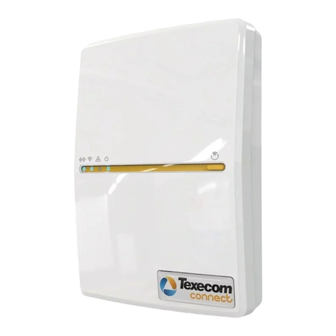
Texecom Premier IXP-W User manual

Installation Manual
Premier IXP-W
INS538

Premier IXP-W Installation Manual
INS538 2
1. Contents
1. Contents........................................................................................................... 2
2. Premier IXP-W Interface ................................................................................ 3
Premier 8XP-W & 32XP-W Firmware............................................................... 3
3. Quick Start Guide............................................................................................ 4
4. System Overview ............................................................................................ 5
Mounting the IXP-W.......................................................................................... 7
Wiring ................................................................................................................ 8
5. Programming................................................................................................... 9
Option Switch Settings................................................................................ 9
Configuring Radio devices .......................................................................... 9
Adding Devices to the Receiver ...................................................................... 9
Ricochet Monitor™ ...................................................................................... 9
Engineers Keypad ....................................................................................... 9
Premier 8XP-W & 32XP-W Learn Switch...................................................... 9
6. Specifications................................................................................................ 10
Electrical ......................................................................................................... 10
Standards........................................................................................................ 11
Warranty.......................................................................................................... 11

Premier IXP-W Installation Manual
3INS538
2. Premier IXP-W Interface
The Premier IXP-W Interface is designed to be used in conjunction with a Premier 8XP-W/32XP-W
Wireless Mesh Networking Expander.
The IXP-W allows you to use Ricochet™ enabled sensors and devices on any control panel.
For the purposes of illustration the Texecom Veritas is shown in this manual as an example for
connection.
This manual should be read along with INS467 for the Premier 8XP-W & 32XP-W, and with any
device specific installation manuals.
Premier 8XP-W & 32XP-W Firmware
The Premier IXP-W is only compatible with firmware version 1.3.4 and later of the Premier 8XP-W &
32XP-W.
To check the firmware version of your receiver you can use either Ricochet Monitor software, or a
Premier Engineers keypad. The firmware version is also printed on a small sticker located on the
main processor on the PCB.
Please see INS467 Installation Instructions Premier 8XP-W/32XP-W or the Ricochet Monitor Help
files.

Premier IXP-W Installation Manual
INS538 4
Connect IXP-W to 8XP-W or
32XP-W 12V 0V T & R
Connect 12V & 0V to control
panel Aux supply
Firmware for the Premier
32XP-W & 8XP-W must be
V1.3.4 or later for the Premier
IXP-W to function
3. Quick Start Guide
Set Option switch 2 Premier
8XP-W/32XP-W to ON
Make Control panel
connections for Zones, Global
Tamper, Global Poll Error &
Global Battery
Learn Devices to the Receiver
with Engineers Keypad,
Ricochet Monitor or onboard
LED’s
See INS467 for more detail
Place Devices in desired
location, use LED to indicate
Signal Security
See INS467 for more detail
Wait 15 Minutes for Mesh
Network to establish
Walk Test System
See INS467
Change Device Attributes
according to application
See INS467

Premier IXP-W Installation Manual
5INS538
4. System Overview
1: Address Switches
Not Used.
2: Option Switches
Only Switch 4 is used to enable/disable Walktest Mode, this is the same as on the receiver, please
see INS467 for more information.
3: Global Poll Error
Connect to a spare Zone on the control panel to signal a polling error from a device.
SYSTEM STATUS INPUTS
1 654
3
2 7
GPE GT GLB
+12V 0V T R
Z8 Z7 Z6 Z5
Z4
Z3 Z2 Z1
Sw1 Sw2
1 2 3 4 5 6
10
11
12
13
14
8
9
7

Premier IXP-W Installation Manual
INS538 6
4: Global Tamper
Connect to Global Tamper, or a spare circuit on the control panel to indicate Tamper on either a
device, the IXP-W or the Receiver.
5: Global Low Battery
Connect to a spare zone on the control panel to signal low battery from devices on the system. If
not required link out.
6: Flash Programming Port
For future use.
7: Heartbeat LED
This LED beats once per second.
8: Transmit LED
Pulses when data is being transmitted.
9: Receive LED
Pulses when data is being received.
10: Network Connection
Network connections for connecting the IXP to the receiver.
11: Cover Tamper
Tamper Switch connection.
12: Tamper Disable
Link out to disable cover tamper.
13: Zone Connections
For connecting the IXP-W to the control panel.
14: System Status Connections
For Future Use

Premier IXP-W Installation Manual
7INS538
Mounting the IXP-W
Remove the Screw cover by locating the two small indents on the upper and lower edge with a small
screwdriver, excessive force is not required.
Remove the retaining screw
1
ON
2 4
3 1
ON
2 4
3

Premier IXP-W Installation Manual
INS538 8
Wiring
It is strongly recommended that the system is completely powered down (mains and battery) before
wiring the expander and interface card. Connect the expander to the interface using 4-core cable,
and make all other connections as follows:
Expander
Interface
Panel Description
+ + Aux + +12V Supply
- - Aux - 0V Supply
T T N/A Transmit Data
R R N/A Receive Data
Z1-Z8 Panel Zones Radio Devices
N/C Input
GPE Panel Zone or Separate*
Aux Input
Global Poll Error
N/C Input
GLB Panel Zone or Separate*
Aux Input
Global Low Battery
N/C Input
GT Global Tamper or Separate*
Aux Input
Global Tamper for devices,
Expander & Interface
To ensure correct operation, all four terminals on the interface must be connected to the
corresponding terminals on the expander.
If Global Poll or Global Low battery are not required, link out the connections on the IXP-W.
*Do not wire all of these to the same input!
Standard 7/0.2 alarm cable can be used for most installations. However, under certain
conditions it may be necessary to use screened cable.

Premier IXP-W Installation Manual
9INS538
5. Programming
Option Switch Settings
All switches on the IXP-W should be turned OFF.
Option switch 2 on the Premier 8XP-W/32XP-W should be turned ON.
Configuring Radio devices
Up to 8 wireless devices of any combination can be learnt to the system. When learning devices the
receiver needs to be in “commission mode”, please see INS467 for details.
Adding Devices to the Receiver
Devices can be learned onto the system in three ways. It is highly recommended that Ricochet
Monitor ™ is used to add/delete devices and to monitor system status and the Signal Security™of
the mesh network.
Ricochet Monitor™
To use Ricochet Monitor follow the instructions detailed in the Information files of the programme for
Adding & Deleting Devices.
Engineers Keypad
To use an Engineers Keypad follow the instructions in INS467 the Installation Manual for the Premier
8XP-W & 32XP-W.
Premier 8XP-W & 32XP-W Learn Switch
It is possible to learn devices directly to the receiver using the learn switch on the receiver, to use
this option please follow the instructions in INS467 the Installation Manual for the Premier 8XP-W &
32XP-W.

Premier IXP-W Installation Manual
INS538 10
6. Specifications
Electrical
Operating Voltage 10 - 13.7VDC
Current Consumption <20mA
Network 4-wire standard 7/0.2 alarm cable up to 250m.
Inputs 1 - 8 N/C
Weight Boxed 176g unboxed 151g
Dimensions L147mm x W92mm x H32mm
Operating Temperature -10°C (+14°F) to +50°C (+122°F)
Storage Temperature -20°C (-4°F) to +60°C (+140°F)
Maximum Humidity 95% non-condensing
EMC Environment
Residential, Commercial, Light Industrial
or Industrial

Premier IXP-W Installation Manual
11 INS538
Standards
The Premier IXP conforms to European Union (EU) Low Voltage Directive (LVD) 2006/95/EC. Electro-
Magnetic Compatibility (EMC) Directive (2004/108/EC. RoHS Directive 2002/95/EC this device does
not contain lead, mercury, cadmium, hexavalent chromium, polybrominated biphenyls (PBB) or
polybrominated depheny ethers (PBDE) in more than the percentage described in the EU Directives,
except exceptions described in the EU Directive.
WEEE Directive (2002/96/EC) Products marked with this symbol cannot be disposed of as unsorted
municipal waste in the European Union. For proper recycling, return this product to your local supplier
upon the purchase of equivalent new equipment or dispose of it at designated collection points.
For more information see www.recyclethis.info
EN50131-1 Alarm systems. Intrusion & hold up alarm systems. System requirements. Grade 2 Class II
EN50131-3 Alarm systems. Intrusion & hold up alarm systems. Control and indicating equipment. Grade 2 Class II
PD6662 Scheme for the application of European standards for intrusion and hold up alarm systems. Grade 2
Class II
Warranty
All Texecom products are designed for reliable, trouble-free operation. Quality is carefully monitored
by extensive computerised testing. As a result the Premier IXP-W expander is covered by a two-year
warranty against defects in material or workmanship.
As the Premier IXP-W interface is not a complete alarm system but only a part thereof, Texecom
cannot accept responsibility or liability for any damages whatsoever based on a claim that the
Premier IXP-W interface failed to function correctly. Due to our policy of continuous improvement
Texecom reserve the right to change specification without prior notice.
Premier is a trademark of Texecom Ltd.
Prestige is a trademark of Texecom Ltd.
SmartKey is a trademark of Texecom Ltd.
Ricochet is a trademark of Texecom Ltd.
SignalSecurity is a trademark of Texecom Ltd.
©TEXECOM LTD 2011

Texecom Limited, Bradwood Court, St. Crispin Way, Haslingden,
Lancashire BB4 4PW, England.
Technical Support:
UK Customers Tel: 08456 300 600
(Calls charged at local rate from a BT landline. Calls from other networks may vary.)
International Customers Tel: +44 1278 686197
Email: techsupport@texe.com
© Texecom Limited 2011
INS538
Table of contents
Other Texecom Network Hardware manuals
Popular Network Hardware manuals by other brands

New Media Technology
New Media Technology IP Power 9212 user manual
Cisco
Cisco Rack-Mount and Cable Mgmt. 7505/7010 installation instructions
United Technologies
United Technologies Interlogix TruVision NVR 22 S quick start guide
Triax
Triax TWB 40 Quick instructions
Neoway
Neoway N27 Hardware user's guide

Juniper
Juniper CTP150 manual
