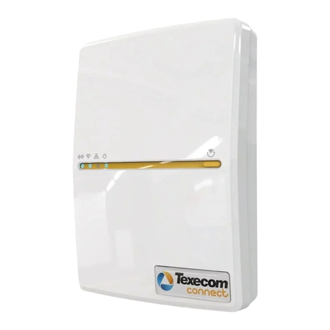
Texecom SmartCom 4G User manual

Texecom SmartCom
4G
INS884EN-4

11-03-2022
• Manual creation
• Corrected Typographical errors
• Updated the managed network port information in section 6.2

INS884EN-4 3/87
Content
1.0 Introduction 4 ............................................................................................................................
2.0 SmartCom 4G 4 ..........................................................................................................................
3.0 Future Support 5 .......................................................................................................................
4.0 Requirements - System 5 .........................................................................................................
4.1 Hardware requirements 6 .......................................................................................................
4.2 Firmware requirements 6 .......................................................................................................
4.3 Network requirements 7 .........................................................................................................
5.0 Texecom Connect 10 .................................................................................................................
6.0 Installation process 12 .............................................................................................................
6.1 SmartCom 4G Opening & Identification 12 .............................................................................
6.2 Removal from mounting tamper 15 ........................................................................................
6.3 Connecting to the Panel 17 ....................................................................................................
6.4 Substitution and Information Security 28 ...............................................................................
6.5 Availability Monitoring 29 ........................................................................................................
6.6 Panel configuration 31 ............................................................................................................
6.7 Generating an App Code 38 ...................................................................................................
7.0 Connecting to the Cloud 39 ......................................................................................................
8.0 Appendix 61 ................................................................................................................................
8.1 Connect V2 App setup 61 .......................................................................................................
9.0 Fault finding & trouble shooting 61 .......................................................................................
9.1 Enable Texecom Connect App - Error Messages 61 ...............................................................
9.2 Frequently Asked Questions 68 ..............................................................................................
10.0 Panel upgrade Local from V1 70 ...........................................................................................
11.0 Specifications 84 .....................................................................................................................

INS884EN-4 4/87
1.0 Introduction
The Texecom SmartCom 4G creates a new generation of simple connectivity for
customers. With the emergence of cloud technologies Texecom has introduced the
SmartCom to take the Premier Elite product line into the future and enable
customers to transition their systems. Texecom are now offering the SmartCom 4G
in addition to the existing SmartCom product.
The SmartCom 4G comes with an in-built world roaming eSIM and there is no
configuration required. Simply connect to the Texecom Cloud by generating an
App code and you can choose between either Single Path 4G or Dual Path with the
IP path as the primary and 4G as the back-up.
The SmartCom 4G supports the Texecom Cloud service and the Texecom Connect
app.
Texecom Monitor
Texecom Monitor enables communication to selected ARC's to provide alarm
signalling based on the requirements of EN50131-1, EN50136-2 and EN50131-10.
Care should be taken when installing systems using Texecom Monitor to ensure
the following requirements are met.
Wi-Fi is not permitted1.
Ethernet connections must use screened cable2.
The antenna lead must be less than 3mtrs long3.
CIE congfiguration should be left at factory settings for Grade 2 or Grade 3. 4.
2.0 SmartCom 4G
The SmartCom 4G is compatible with all Premier Elite panels including Premier
Elite 640, it does require V5.04 firmware or above. It is supplied as a separate
module that is connected to two COM Ports within the panel. For those familiar
with fitting the SmartCom product the SmartCom 4G follows exactly the same
process.

INS884EN-4 5/87
Key Features
Ethernet and WiFi
GSM - 4G connection (also connects to 2G and 3G networks, when no 4G is
available)
In built eSIM - for security
Private secure APN connection
Enables Texecom Connect (V2) and Texecom Cloud Service
Easy integration with Premier Elite V5.04 firmware
Compatible with future cloud systems management
Simple user web page for WiFi configuration
Secure - no need to open firewalls for port forwarding
3.0 Future Support
At launch SmartCom 4G will not provide alarm signalling services. SmartCom 4G
has been designed to enable it to be used to provide dual path EN50136 graded
communicators for secure alarm transmission. This will provide connection direct
to ARC’s as primary signalling services. This solution is branded Texecom Monitor
and will be released later this year. At that point your SmartCom 4G will be
firmware upgradeable to support this service.
4.0 Requirements - System
To setup a Texecom Cloud connection or Texecom Connect system you will need
the following as a bare minimum:
A Texecom Premier Elite security system with V5.04 or later firmware
installed
SSID & Password for the Network if you intend to connect by WiFi
A Texecom SmartCom 4G (also with Ethernet & WiFi)
A Texecom Cloud Installers account
Texecom Connect V2 App for iOS or Android (to use the Texecom Connect
service)
When attaching the system to the cloud you will be offered alternative

INS884EN-4 6/87
service plans for
Texecom Connect app visibility
System and Texecom Connect management
Note: Service plans include payment for 4G data plans
4.1 Hardware requirements
The following hardware is compatible with the Texecom Connect (V2) app.
Premier Elite Control Panel (live-front, polymer or metal)
Premier Elite 12, 12-W, 24-W & 48-W (discontinued, but may be flash
upgraded, see Section 8)
Premier Elite 24
Premier Elite 48
Premier Elite 64-W
Premier Elite 88
Premier Elite 168
Premier Elite 640
Communication Module
Texecom SmartCom (WiFi and Ethernet)
Texecom SmartCom 4G (also with Ethernet and WiFi)
Security & Other Devices
All wired and Ricochet enabled wireless devices
Texecom Connect SmartPlug
4.2 Firmware requirements
The following firmware and software versions are required to fully use Texecom
Connect V2 App and the Texecom Cloud Services
Premier Elite Control Panel Firmware* V5.04 and above
NOTE: The control panel firmware can be upgraded using the Premier Elite Flasher

INS884EN-4 7/87
Interface. See Appendix A.
4.3 Network requirements
Texecom Connect needs to be able to communicate with the outside world so that
push notifications can be sent to the users device; and so that commands from the
device can be sent to the system.
Wherever possible you should always use Ethernet as the primary connection, this
offers the most stable and reliable connection type. WiFi may be used as the
primary path and 4G should be used as secondary signal path in all dual path
configurations.
Note: Screened Ethernet cable should be used in all installations.
Where a physical connection is not possible then the SmartCom 4G offers the
facility to switch resiliently between available networks via the roaming eSIM.
Should a fault occur on one network it will switch to the next best available
network. During configuration you can use the "SmartCom 4G radio signal" screen
to check how many alternative networks are available. The page provides a
resilience checker that gives an indication as to whether there are enough
alternative network options available.
Complete connecting the panel to the Texecom Cloud service (Section 7) and then
use the 'SmartCom 4G radio signal' facility to improve antenna location.
The Refresh button can be used to test alternative locations for the antenna to
improve signal strength and the The Re-scan button is used to check additional
alternative networks (note a Re-scan will disconnect from the current connection).
Texecom also check the signal quality by measuring the response time of the
network regularly, this enables the SmartCom 4G to validate the current
connection regularly. If the response time of the network degrades substantially
then the SmartCom 4G will automatically compare the network options again and
re-select an alternative.
For WiFi you will need access to the end users site network SSID & password,

INS884EN-4 8/87
which must have a router or router/modem. Modem only systems are not
supported.
For Ethernet and WiFi connections SmartCom 4G functions best on networks with
DHCP enabled. If you need to set a static IP address details can be found in the
section Managed Networks which details Static IP.
SmartCom 4G operates at 2.4 GHz WiFi supporting 802.11b/802.11g & 802.11n
wireless technology. 5GHz networks are not supported.

INS884EN-4 9/87

INS884EN-4 10/87
5.0 Texecom Connect
The Texecom Connect app is reliant on an existing Texecom security system in
order for it to work. Below is an overview of the full Texecom Connect system so
you can understand the full ecosystem.
Note: The Texecom connect app is a supplementary feature and not considered
part of the graded ATS
Note: Screened Ethernet cable should be used for all installations.

INS884EN-4 11/87

INS884EN-4 12/87
6.0 Installation process
To enable the use of the Texecom Cloud services or Texecom Connect (V2) app
please follow the following steps:-
Physically install your control panel and security system (upgrading the
control panel firmware if necessary see section 11)
Configure the control panel and security system.
Install & configure the SmartCom 4G (the device should be fixed to a solid
surface using the appropriate sized screws, and utilising both fixing points.
Ensure the rear tamper breakout is fixed to the mounting substrate)
Minimum screw size 3.5 X 16mm CSK
Maximum screw size 4.0 X 70mm CSK
Connect the SmartCom 4G to the Texecom Cloud service
Purchase a service plan
Check your SmartCom 4G signal resilience
Invite customers to the Texecom Connect app using App management
6.1 SmartCom 4G Opening & Identification
The Texecom SmartCom 4G is an advanced intelligent communicator compatible
with all Premier Elite control panels with V5.04 or later firmware installed.
The SmartCom 4G is remotely upgradable enabling new features and functions to
be delivered to the device over the air, reducing the need for site visits. It is also
possible to remotely upgrade the control panel via the Texecom Cloud.
By default the SmartCom 4G obtains its IP address by DHCP which must be
enabled on the router. It is possible to utilise a static IP address which is detailed in
section Static IP Feature
Device LED Indications
The Cloud LED will be on solid when connected to our servers and all
information is correct to enable bi-directional communication.
The LAN or WiFi/4G LED will be on solid when connected to the network. The

INS884EN-4 13/87
Lan LED will be illuminated when connected by ethernet cable.
The Power LED should be on solid.
If the Cloud LED is flashing, please check that the system is configured
correctly. If symptoms persist and the light does not go solid please contact
Tech Support.
When a firmware upgrade is taking place all LED’s may flash sporadically,
this is normal.
Device LED Indications
Cloud WiFi Ethernet Mobile
Comms
Function Connection to
Cloud server WiFi connection Ethernet
connection
4G modem
connection
Off No power No connection
configured No local link No modem or
not configured
Flash
(2.5hz)
No cloud
connection
Connection
configured but
in path fail
Local link
present but in
path fail
Mobile
configured but
in path fail
On Cloud
connected Path connected Path connected Path
connected
Any other
state AP mode - Fast
Flash (0.5hz)
No local server
connection (No
IP or other fault)
Fast flash
(0.5hz) (NTH)
Modem LED indications
The modem has 4 status LED’s. They will display the following:

INS884EN-4 14/87
Modem LED indications
LED1 LED2 - APN LED3 - mobile
net
LED4 -
power
Solid N/A Registered Registered Powered
Off N/A Not registered Not registered No power
Flashing N/A Registering Registering N/A
Note: The modem is NOT plug and play, if the modem USB has been unplugged,

INS884EN-4 15/87
the SmartCom 4G must be power cycled to enable the modem.
Note: See Section 10 FAQ’s & Troubleshooting.
6.2 Removal from mounting tamper
The removal from mounting tamper should be used for all installations. Ensure a
suitable sized screw and fixing is used for the substrate where the device is
mounted. Forced removal of the device from the mounting surface will cause the
plastic to be break and cause a tamper condition.
Note: The plastic housings rear tamper breakout is sacrificial and cannot be
reinstated.

INS884EN-4 16/87

INS884EN-4 17/87
6.3 Connecting to the Panel
The SmartCom 4G requires two Com Ports on the control panel. The 4 wire
connector identified as SmartCom in the panel Com Port device list, the two wire
connector identified as ComIP in the panel Com Port device list.
A Premier Elite ComPort+ is provided which may be used to utilise the digi modem
connection to provide Com Port 3 on Premier Elite 24/48/64/88 & 168. The Premier
Elite 640 has 3 Com Ports.
Insert the black connector into the SmartCom.
DO NOT EXTEND THE LENGTH OF THE SUPPLIED CABLE. DOING SO
MAY RENDER THE UNIT INOPERABLE AND MAY INHIBIT OVER THE
AIR UPGRADES OF BOTH THE SMARTCOM 4G AND THE PANEL.
Note: the yellow wire should be on the upper right hand side.
Plug the 4 wire connector onto Com Port 1 on the Control Panel. This should be
configured as SmartCom.
Plug the 2 wire connector onto Com Port 2 on the Control Panel. This should be
configured as Com IP

INS884EN-4 18/87
Ethernet DHCP
To operate as an Ethernet Communicator, plug a screened Ethernet cable into the
SmartCom 4G and the other end into a spare LAN port on the router or switch.
By default you do not need to know any details from the router for the system to
work. An IP address will be assigned by DHCP from the router, and automatically
programmed into the panel.
Managed Networks
The SmartCom 4G communicator has been designed to work with minimal setup or

INS884EN-4 19/87
help from IT professionals, however on high security or managed networks
typically seen in larger commercial properties, it may be necessary to open some
outbound ports to ensure the SmartCom 4G operates correctly.
Remember the SmartCom 4G does not require any inbound ports to be opened on
the network, this ensures the network remains as secure as possible. We
recommend following the below steps for correct operation of your SmartCom 4G
communicator.
Where you suspect a network may be restricted, we suggest sending the below
port list to the IT administrator prior to attending site. Or if it’s easier you can ask
the IT administrator to perform a wildcard setup opening all outbound traffic to
*.texe.com and *.pool.ntp.org.
Static IP Feature
A static IP address can be manually assigned to the SmartCom 4G.
Currently this is for ETHERNET CONNECTIONS ONLY (doesn't affect WiFi which
remains as DHCP). The IP data is entered into the panel in the same way as for a
Com-IP module.
Enter Engineer mode on the keypad.
Enter Engineer mode on the keypad.1.
Press 7 then y/y (UDL/Digi Options).2.
Press 7 then y/y for (Setup Modules).3.
Press 2 then y/y for (Setup IP data). Then select Com Port 2.4.
Press n/n and enter the IP address of the ComIP you noted in the5.
previous steps. Pressing y/y when complete. Pressing the O/B key
twice will enter a dot. For Example 192.168.0.150
Scroll down once to change the port number. This is required if you wish to6.
setup port forwarding through the router. The port can be left as 10001.
Scroll down and enter the Gateway address assigned to the ComIP.7.
Scroll down once and enter the subnet mask assigned to the ComIP.8.
Press N/N three times.9.
Press 8 then y/y (Com Port Setup).10.
Scroll to the comport you have the ComIP plugged onto.11.

INS884EN-4 20/87
Press n/n 4 and y/y for ComIP module.12.
The IP data should be entered for the ComIP com port of the SmartCom prior to
Com Port Setup (just like for Com-IP modules)
The data is uploaded to the SmartCom when the Com Port is changed from
'Nothing Fitted' to 'ComIP'.
It takes up to 45 seconds for the data to be uploaded to the SmartCom.
The SmartCom 4G can be returned to DCHP mode by clearing the IP data from the
panel com port and then changing the comport to 'Nothing Fitted' and then back to
'ComIP'. When the blank IP data is uploaded the SmartCom will automatically
switch back to DHCP mode.
IP addresses will only show for the ComIP com port. This is normal and correct.
Another way to revert back to DCHP mode is to use the new SmartCom 4G default
procedure.
To default SmartCom:
Remove SmartCom cover to create a tamper condition.1.
Press the Wi-Fi button 5 times within 3 seconds.2.
All four LEDs will flash for 10 seconds and then the SmartCom will reboot into3.
a default state.
WiFi
To enable a WiFi connection you will need access to the customers network SSID &
password. The SmartCom 4G will only function on networks with DHCP enabled.
The SmartCom 4G operates at 2.4 GHz supporting 802.11b/802.11g & 802.11n
wireless technology. 5GHz bands are not supported.
Table of contents
Other Texecom Network Hardware manuals
