Textron Aviation Cessna 525B User manual

TEXTRONAVIATIONINC.
AIRCRAFTDIVISION
WICHITA,KANSAS67277
ELEVATORTRIMSERVOCAPSTANCABLERETENTION
IMPROVEMENT
ICASupplement
MODELNO:525B
SUPPLEMENTNO:ICA-525B-27-00009
SUPPLEMENTDATE:7/13/2020
©TEXTRONAVIATIONINC.
Form2261Rev1

TEXTRONAVIATIONINC.
AIRCRAFTDIVISION
WICHITA,KANSAS67277
REVISIONS
ICA-525B-27-00009Rev:-Date:Jul/13/2020
ICASummaryPages1-6
ManualsAffectedDescriptionTitle
MaintenanceManual27-30-02pages
401-427
ELEVATORANDTABSYSTEMCOMPONENTS-
REMOVAL/INSTALLATION
•ThissectioncontainstherevisedproceduresforinstallationoftheGSM86ElevatorTrimServo
GearboxandCable.
AppendixA:IllustratedParts
Catalog
SeeAttached
PartsT able
AppendixB:WiringDiagram
Manual
NOTUSED
1.ExportCompliance
A.ThispublicationcontainstechnicaldataandissubjecttoU.S.exportregulations.Thisinformationhas
beenexportedfromtheUnitedStatesinaccordancewithexportadministrationregulations.Diversion
contrarytoU.S.lawisprohibited.
ECCN:9E991
2.RevisionBars
A.RevisionbarsinthisICAsupplementidentifynewICAsand/orchangestothecurrentICAsinthe
releasedmaintenancemanual.
•NewICAsthatarenotinthecurrentmaintenancemanualwillhavearevisionbarfromtopto
bottomalongtheleftmargin.
•ICAsthatareinthecurrentmaintenancemanualandhaveinformationadded,deletedorrevised
willhavearevisionbar(s)intheleftmarginadjacenttotheadded,deletedorrevisedinformation.
•Neworchangedillustrationswillhaveachangebarfortheentirelengthofthepage.
3.PageNumbering
A.ThepagenumbersystemforICAincludedinthissupplementhavethree-elementnumbersthatare
separatedbydashes.Thethree-elementnumberisfoundatthebottomrightcornerofthepage,left
ofthepagenumber.Thedateisfoundbelowthepagenumber.
B.Whenthechapter/systemelementnumberisfollowedwithzerosinthesection/subsystemand
subject/unitelementnumber(28-00-00),theinformationisapplicabletotheentiresystem.
Page1of6
Jul13/2020
©TEXTRONAVIATIONINC.
ICA-525B-27-00009Form2261Rev1

TEXTRONAVIATIONINC.
AIRCRAFTDIVISION
WICHITA,KANSAS67277
C.Whenthesection/subsystemelementnumberisfollowedwithzerosinthesubject/unitelement
number(28-21-00),theinformationisapplicabletothesubsystemsinthesystem.
D.Thesubject/unitelementnumberisusedtoidentifyinformationapplicabletounitsinthesubsystems.
Thesubject/unitelementnumbercontinuesinsequencefromthenumber-01-withthenumberof
subsystemunitsinwhichmaintenanceinformationisnecessary.
E.Allsystem/subsystem/unit(chapter/section/subject)maintenancedataisseparatedintospecied
typesofinformation:DescriptionandOperation,Troubleshooting,MaintenancePractices,etc.
Blocksofpagenumbersthatareinsequenceareusedtoidentifythetypeofinformation:
(1)DescriptionandOperationorTroubleshootinginformationmaynotbeincludediftheprocedure
iseasy.Whensubtopicsareshort,theymaybeputtogetherintotheMaintenancePractices
section.MaintenancePracticescanhaveamixofsubtopicsthatincludesinformationtoservice,
remove,install,adjust,test,clean,paintordoapprovedrepairs.
(2)Longerproceduresthatarenotaseasytodomaybeincludedinaspeciedsection.
Page1through99-DescriptionandOperation
Page101through199-Troubleshooting
Page201through299-MaintenancePractices
Page301through399-Servicing
Page401through499-Removal/Installation
Page501through599-Adjustment/T est
Page601through699-Inspection/Check
Page701through799-Cleaning/Painting
Page801through899-ApprovedRepairs
F.Atypicalpagenumber:
G.Illustrationsusethesamegurenumbersasthepageblockinwhichtheyappear.Forexample,Figure
202wouldbethesecondgureinaMaintenancePracticessection.
4.SupplementRevisions
A.Revisionstothissupplementmaybeaccomplishedifchangestothissupplementarerequiredafter
releaseoftheoriginalissueandpriortoincorporationintothemanualslistedintheREVISIONStable.
B.Allrevisionstothissupplementwillhavechangesidentiedindetailintherevisionblock(s)above.
C.AllpagesinthisICAsupplementwillhavethesamedateandarevalidasofthedateshown.
5.ICAIncorporationintoApplicableManuals
NOTE:MostICAsupplementswillbeincorporatedinthenextavailablerevisiontothemanuals
listedaboveandshouldbeusedinconjunctionwiththosemanualsuntilthenextavailable
revisionisreleased.
A.TheICASupplementListlocatedintheIntroductionsectionofeachmanuallistedintheREVISIONS
tablewillindicatetheincorporationstatusasofthereleasedateofthepublishedrevision.
Page2of6
Jul13/2020
©TEXTRONAVIATIONINC.
ICA-525B-27-00009Form2261Rev1

TEXTRONAVIATIONINC.
AIRCRAFTDIVISION
WICHITA,KANSAS67277
B.Themanualrevisionlevelofthesupplementincorporationwillbelistedinthe"ManualIncorporation
Status"columnintheICASupplementList,whenthoseICAsassociatedwiththatmanualhavebeen
incorporated.AfterICAsareincorporated,themanualthattheyareincorporatedinmustnowbeused
forthoseICAsinsteadofthesupplement.
•Basedonrevisioncycletimesfortheaffectedmanuals,MMICAs,WDMICAs,etc.inthis
supplementmaybeincorporatedinthemanualsatdifferenttimes.
•Therewillnotbearevisiontothissupplementtoindicateincorporationinthemanuals.Usersare
requiredtochecktheICASupplementListforeachmanualaffectedtodetermineincorporation
status.
C.ThissupplementwillbecompletelysupersededbythemanualslistedintheREVISIONStablewhen
ithasbeenincorporatedinallofthemanuals.
Page3of6
Jul13/2020
©TEXTRONAVIATIONINC.
ICA-525B-27-00009Form2261Rev1

TEXTRONAVIATIONINC.
AIRCRAFTDIVISION
WICHITA,KANSAS67277
INTRODUCTION
1.Purpose
A.ThepurposeofthisSupplementistoprovidethemaintenancetechnicianwiththeinformation
necessarytoensurethecorrectfunctionalityandperformanceoftheELEVATORTRIMSERVO
CAPSTANCABLERETENTIONIMPROVEMENTontheCessnaModel525Buntilthisinformation
getsincorporatedintothenextrevisiontothemanualslistedinthe"REVISIONS"sectionofthis
supplement.
B.ThisICAsupplementisdesignedtosatisfytherequirementsof14CFR23.1529"Instructionsfor
ContinuedAirworthiness"associatedwiththisinstallation.Thisdocumentisasupplementtothe
Model525BMaintenanceManualandwillbeincorporatedinthenextrevisiontothemanual.
C.Whenthisinformationisincorporatedinthenextrevisiontothemanualslistedinthe"REVISIONS"
section,thosemanualsshalltakeprecedenceoverthissupplementaldocument.Refertothe"ICA
SupplementList"inthe"Introduction"sectionoftherespectivemanualforthestatusofallapplicable
ICASupplements.
D.RevisionstothissupplementmayoccurifthereisachangetoanyoftheICAsinthissupplement
priortoincorporationintoalloftheaffectedmanuals.
NOTE:Thisdocumentmustbeplacedwiththeaircraftoperator'sTechnicalLibraryCD-ROM
orModel525BMaintenanceManualandincorporatedintotheoperator'sscheduled
maintenanceprogram.
2.Effectivity
A.TheseInstructionsforContinuedAirworthiness(ICA)areeffectiveforthefollowingaircraftmodeland
serialization.
ModelBeginningEffectivityEndingEffectivity
525B-0632andOn
3.CompleteICADocuments
A.Thefollowingdocument(s),inconjunctionwiththissupplement,constitutetheInstructionsfor
ContinuedAirworthinessfortheELEVATORTRIMSERVOCAPSTANCABLERETENTION
IMPROVEMENTontheCessnaModel525B.Allitemsmustbeavailabletotheoperatoratinitial
delivery.
(1)Model525BMaintenanceManual
4.SystemComponents
A.RefertoAppendixA:IllustratedPartsCatalog
Page4of6
Jul13/2020
©TEXTRONAVIATIONINC.
ICA-525B-27-00009Form2261Rev1

TEXTRONAVIATIONINC.
AIRCRAFTDIVISION
WICHITA,KANSAS67277
LISTOFINSTRUCTIONSFORCONTINUEDAIRWORTHINESS
1.Model525BMaintenanceManual
A.Chapter27FlightControls
(1)ATA27-30-02ElevatorandT abSystemComponents-Removal/Installation
Page5of6
Jul13/2020
©TEXTRONAVIATIONINC.
ICA-525B-27-00009Form2261Rev1

TEXTRONAVIATIONINC.
AIRCRAFTDIVISION
WICHITA,KANSAS67277
INSPECTIONPROGRAMANDAIRWORTHINESSLIMITATIONS
1.ContinuousInspectionProgram
A.ThisICASupplementdoesnotaffectthecurrentinspectionprogram.
2.AirworthinessLimitations
A.CessnaAircraftCompanyModel525BMaintenanceManual,Chapter4,AirworthinessLimitations,
containsthesystemandairframelimitationsfortheModel525B.
NOTE:TheAirworthinessLimitationssectionisFAA-approvedandspeciesmaintenance
requiredunderSection43.16and91.403ofTitle14CodeofFederalRegulations,unless
analternativeprogramhasbeenFAAapproved.
(1)Therearenonew(oradditional)airworthinesslimitationsassociatedwiththisequipmentand/or
installation.
Page6of6
Jul13/2020
©TEXTRONAVIATIONINC.
ICA-525B-27-00009Form2261Rev1


CESSNA®
MODEL525B
MAINTENANCEMANUAL
ELEVATORANDTABSYSTEMCOMPONENTS-REMOVAL/INSTALLATION
1.General
A.Thissectiongivesinformationabouttheremovalandinstallationofcomponentsrelatedtotheelevator
andelevatortrimtabsystems.Forcontrolcableremoval/installationandrigginginformation,referto
ElevatorandT abSystemControlCables-MaintenancePractices.
B.Forremovalandinstallationoftheelevator,refertoChapter55,Elevator-Removal/Installation.
2.ToolsandEquipment
A.Foralistoftoolsandequipment,refertoFlightControls-General.
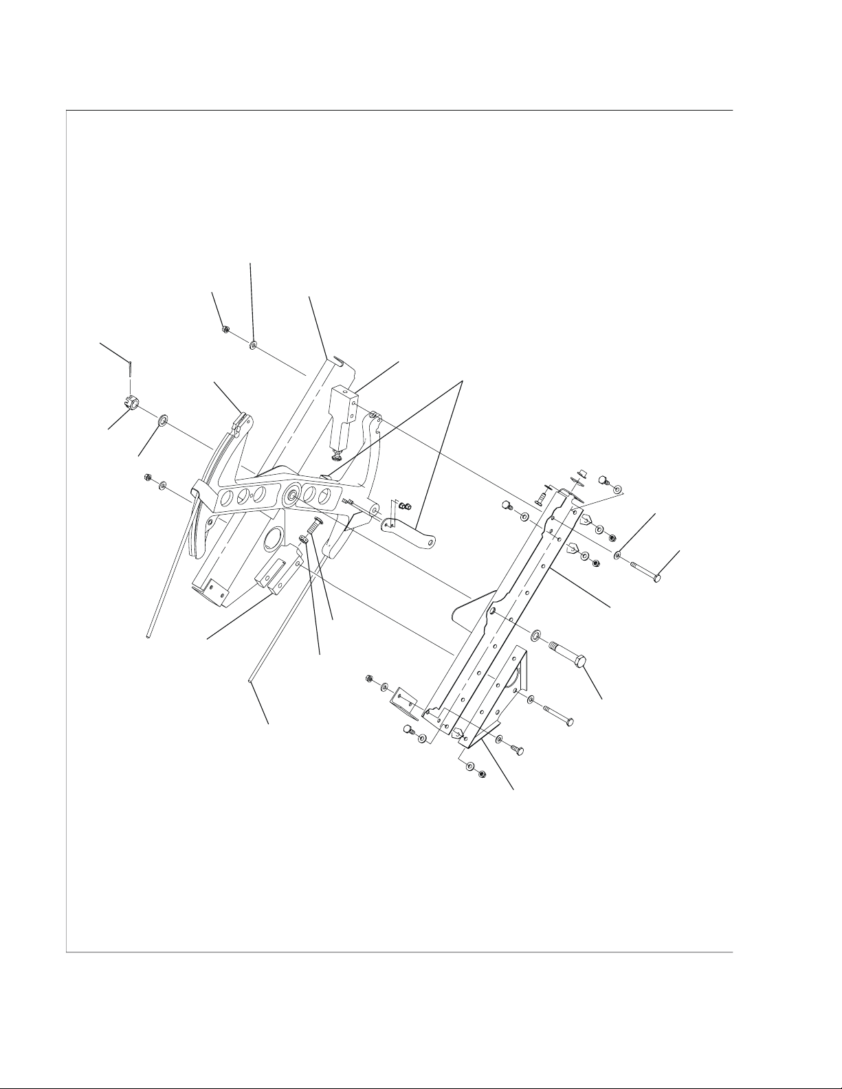
3.ForwardElevatorSectorAssemblyRemoval/Installation
A.RemovetheForwardElevatorSectorAssembly(Airplanes-0001thru-0056and-0058thru-0450)
(RefertoFigure401).
(1)Removethecopilot'sseat.RefertoChapter25,FlightCrewSeats-MaintenancePractices.
(2)Getaccesstotheforwardelevatorsector.
(a)Removethecockpitoorboardpanels251BTCand251CTC.RefertoChapter6,Access
PlatesandPanelsIdentication-DescriptionandOperation.
(3)Getaccesstotheelevatorcontrolcableturnbuckles.
(a)Removethetailconebaggagepanel321BL.RefertoChapter6,AccessPlatesandPanels
Identication-DescriptionandOperation.
(4)Installarigpinintheaftsector.
(a)Removetheclipandloosentheelevatorautopilotcableturnbuckle.
(b)Removethesafetyclipsandloosentheelevatorcontrolcableturnbuckles.
(5)Identifyandlabeltheforwardelevatorcontrolcables.
(6)Removethenuts,washers,andscrewsthatkeeptheforwardelevatorcablesintheforward
elevatorsector.Keepthehardware.
(7)Removethecotterpin,nut,washers,andboltthatattachtheconnectinglinktotheforward
elevatorsector.
(8)Removethescrewsthatattachthestopblocktotheupperandlowersectorbrackets.
(9)Removethesafetywire,pivotbolt,andwasherthatattachtheforwardelevatorsectortoupper
andlowersectorbrackets.
(10)Removethescrewsthatattachtheuppersectorbrackettolowersectorbracket.
(a)Removetheaileronandruddertrimcontrols.
(b)Removeuppersectorbracket,spacer,andstopblock.
(11)Removetheforwardelevatorsectorfromairplane.
B.InstalltheForwardElevatorSector(Airplanes-0001thru-0056and-0058thru-0450)(RefertoFigure
401).
(1)Puttheforwardelevatorsectorinpositiononthelowersectorbracket.
(2)Putthestopblockinpositiononthelowersectorbracket.
(3)Puttheuppersectorbracketandspacerinpositiononthelowersectorbracket.
(4)Putthewasheronthepivotboltandattachthesectorassemblytotheupperandlowersector
brackets.
(5)Attachthestopblocktothesectorbracketswithtwoscrews.
(6)Putasafetywireonthepivotbolthead.RefertotheCitationStandardPracticesManual,Chapter
20,Safetying-MaintenancePractices.
(7)Installthescrewsthatattacheachendoftheuppersectorbrackettothelowersectorbracket.
(8)Installtheforwardelevatorcablesintheforwardelevatorsectorwiththescrews,washers,and
nutskeptfromtheremoval.
(9)Attachtheconnectinglinktoforwardelevatorsectorwithabolt,washers,nut,andcotterpin.
(a)Installtheaileronandruddertrimcontrolsremovedbefore.
(10)Rigtheelevatorcontrolsystemcablesandadjustthestopbolts.RefertoElevatorandTab
SystemControlCables-MaintenancePractices.
(11)Installthetailconebaggagecompartmentpanel321BL.RefertoChapter6,AccessPlatesand
PanelsIdentication-DescriptionandOperation.
27-30-02Page401
©TEXTRONAVIATIONINC.Jul13/2020
ICA-525B-27-00009Form2261Rev1

CESSNA®
MODEL525B
MAINTENANCEMANUAL
A29101
A
BOLT
SPACER
WASHER
PIVOT
BOLT
SCREW
UPPER SECTOR
BRACKET
STOP
BLOCKSTOP
BOLT
NUT
FORWARD
ELEVATOR
CABLE, RIGHT
STOP
BOLT
FORWARD
ELEVATOR
CABLE, LEFT
LOWER SECTOR
BRACKET
SCREW
NUTCOTTER PIN
WASHERROD END
CONNECTING
LINK
WASHER
6310T1072
A6363T1017
DETAIL AAIRPLANES −0001 THRU −0056 AND
AIRPLANES −005 THRU −0450
ForwardElevatorSectorInstallation
Figure401(Sheet1)
27-30-02Page402
©TEXTRONAVIATIONINC.Jul13/2020
ICA-525B-27-00009Form2261Rev1

CESSNA®
MODEL525B
MAINTENANCEMANUAL
A94137
A6315T116
PIVOT BOLT
UPPER BRACKET
STOP BLOCK
STOP BOLT
ELEVATOR CABLE
(RIGHT)
FORWARD
ELEVATOR
SECTOR
ELEVATOR CABLE
(LEFT)
LOWER BRACKET
ROD END
CONNECTING
LINK
SPACER
SCREW
TRIM BEARING PLATE
WASHER
BOLT
WASHER
WASHER
NUT
COTTER PIN
NUT
SCREW
DETAIL AAIRPLANES −0057 AND −0451 AND ON
ForwardElevatorSectorInstallation
Figure401(Sheet2)
27-30-02Page403
©TEXTRONAVIATIONINC.Jul13/2020
ICA-525B-27-00009Form2261Rev1

CESSNA®
MODEL525B
MAINTENANCEMANUAL
(12)Installcockpitoorboardpanels251BTCand251CTC.RefertoChapter6,AccessPlatesand
PanelsIdentication-DescriptionandOperation.
(13)Installthecopilot'sseat.RefertoChapter25,FlightCrewSeats-MaintenancePractices.
C.RemovetheForwardElevatorSectorAssembly(Airplanes-0057and-0451andOn)(RefertoFigure
401).
(1)Removecopilotsseat.RefertoChapter25,FlightCrewSeats-MaintenancePractices.
(2)Gainaccesstotheforwardelevatorsectorbyremovingpanels251BTCand251CTC.Referto
Chapter6,AccessPlatesandPanelsIdentication-DescriptionandOperation.
(3)Gainaccesstotheelevatorcontrolcableturnbucklesinthetailconebyremovingpanel321BL.
RefertoChapter6,AccessPlatesandPanelsIdentication-DescriptionandOperation.
(4)Disconnecttheelevatorforwardtrimcablesfromthechainatthecontrolpedestalinthecockpit.
RefertoElevatorandTabSystemControlCables-MaintenancePractices.
(5)Disconnecttherudderforwardtrimcontrolcablesfromthechainatthecontrolpedestalinthe
cockpit.RefertoRudderandT abSystem-MaintenancePractices.
(6)Disconnectthefuselageailerontrimcablesfromthechainatthecontrolpedestalinthecockpit.
RefertoAileronandT abSystemControlCables-MaintenancePractices.
(7)Removesafetyclipsandloosenelevatorcontrolcableturnbuckles.
(8)Removenuts,washersandscrewssecuringelevatorcontrolcablestoforwardsector.
(9)Taganddisconnectelevatorcontrolcables.
CAUTION:Becarefultopreventdamagetotheavionicsdisplayswhenyou
disconnecttheconnectinglinkfromtheforwardelevatorsector.
Thecontrolcolumncanfallforwardanddamagethedisplaysif
protectivepadsorfoamcoversarenotinstalledontheavionics
displays.
(10)Putaprotectivepadorfoamcoverontheavionicsdisplays.
(11)Removeanddiscardthecotterpinfromthenutandtheboltthatconnecttheforwardelevator
connectinglinktotheforwardelevatorsector.
(a)Removethenut,washers,andboltandcarefullymovethecontrolcolumnsforwardasyou
disconnecttheconnectinglinkfromthesector.
(12)Removetheaftpedestalswitchpaneltogetaccesstotheailerontrimgearbox.RefertoChapter
31,InstrumentandSwitchPanels-MaintenancePractices.
(13)Removethescrews,washers,andnutsthatattachtheailerontrimgearboxtothepedestal
structure.
(14)Removethescrewsthatattachtheruddertrimgearboxtothepedestalstructure.
(15)Removethescrewsthatattachthetrimbearingplatetotheuppersectorbracket.
(16)Liftthesprocketssufcientlytopullthebearingplateawayfromtheuppersectorbracket.
(a)Removethebearingplatefromtheairplane.
(17)Removescrewssecuringstopblocktoupperandlowersectorbrackets.
(18)Removesafetywire,pivotboltandwasherssecuringsectorassemblytoupperandlowersector
brackets.
(19)Removescrewssecuringuppersectorbrackettolowersectorbracket.Removeuppersector
bracketandstopblock.
(20)Removeelevatorsectorfromairplane.
D.InstalltheForwardElevatorSectorAssembly(Airplanes-0057and-0451andOn)(RefertoFigure
401).
(1)Positionforwardelevatorsectorassemblyinitspositiononthelowersectorbracket.
(2)PuttheNAS43DD6-29spacerontopoftheforwardelevatorsectorassemblybearing.
(3)Puttheuppersectorbracketinitspositionontheforwardelevatorsector.
(a)Looselyinstallthepivotboltwiththewasherthroughtheuppersectorbracket,spacer,
forwardelevatorsector,andlowersectorbracket.
(4)Putthestopblockinitspositionbetweentheupperandlowersectorbracket.
(a)Looselyinstallthescrewsthatattachthestopblocktotheupperandlowersectorbrackets.
(5)Installthescrewsthatattachtheuppersectorbrackettothelowersectorbracket.
(6)Tightenthescrewsthatattachthestopblocktotheupperandlowersectorbrackets.
27-30-02Page404
©TEXTRONAVIATIONINC.Jul13/2020
ICA-525B-27-00009Form2261Rev1

CESSNA®
MODEL525B
MAINTENANCEMANUAL
(7)Tightenthepivotbolt.
(a)Safetythepivotboltwithsafetywire.RefertotheCitationStandardPracticesManual,
Chapter20,Safetying-MaintenancePractices,SafetyWireInstallation.
(8)Installelevatorcablestoelevatorsectorassemblyusingscrews,washersandnuts.
(9)Looselyputthetrimbearingplateassembly,aileronsprocket,andruddertrimsprocketintheir
positionontheuppersectorbracket.
(a)Makesurethatthechainsareintheircorrectroutingpositionsonthesprockets.
(b)Installthescrewsthatattachthetrimbearingplateassemblytotheuppersectorbracket.
(10)Puttheruddertrimgearboxinitspositiononthepedestalstructure.
(a)Installthescrews.
(11)Puttheailerontrimgearboxinitspositiononthepedestalstructure.
(a)Installthescrews,washers,andnuts.
(12)Connectthefuselageailerontrimcablestothechainatthecontrolpedestalinthecockpit.Refer
toAileronandTabSystemControlCables-MaintenancePractices.
(13)Connecttherudderforwardtrimcontrolcablestothechainatthecontrolpedestalinthecockpit.
RefertoRudderandTabSystem-MaintenancePractices.
(14)Connecttheelevatorforwardtrimcablestothechainatthecontrolpedestalinthecockpit.Refer
toElevatorandTabSystemControlCables-MaintenancePractices.
(15)Attachthecontrolcolumnconnectinglinktoelevatorsectorassemblyusingbolt,washers,
nutandcotterpin.RefertotheCitationStandardPracticesManual,Chapter20,Safetying-
MaintenancePractices,CotterPinInstallation.
(16)Dotheriggingoftheelevatorcontrolsystemcablesandtheadjuststopblocks.RefertoElevator
andTabSystemControlCables-Adjustment/Test.
(17)Installtheaftpedestalswitchpanel.RefertoChapter31,InstrumentandSwitchPanels-
MaintenancePractices.
(18)Installpanel321BL.RefertoChapter6,AccessPlatesandPanelsIdentication-Description
andOperation.
(19)Installpanels251BTCand251CTC.RefertoChapter6,AccessPlatesandPanelsIdentication
-DescriptionandOperation.
(20)Installthecopilotseat.RefertoChapter25,FlightCrewSeats-MaintenancePractices.
(21)Removetheprotectivepadorfoamcoverfromtheavionicsdisplays.
4.AftElevatorSectorRemoval/Installation
NOTE:Theleftelevatorsectorchannelcanberemovedtohelpwithremovaloftheaftelevatorsector.
Therightsectorchannelisrivetedtothestructure.
A.RemoveAftElevatorSector(RefertoFigure402).
(1)Getaccesstotheelevatorcontrolcableturnbuckles.Removetailconebaggagepanel321BL.
RefertoChapter6,AccessPlatesandPanelsIdentication-DescriptionandOperation.
(2)Carefullyclampthehornstothehorizontalstabilizertoattachbothelevatorsurfaces.
(a)Removethesafetyclipsandloosentheelevatorcontrolcableturnbuckles.
(3)Getaccesstotheaftelevatorsectorandaftelevatorcontrolcables.Removeverticalstabilizer
accesspanels340ATC,340AL,340AR,340BL,340BR,340DL,340EL,340CRand340ER.
RefertoChapter6,AccessPlatesandPanelsIdentication-DescriptionandOperation.
(4)Removethescrewsandnutsthatattachtheretainersoverthepushrodattachboltintheaft
elevatorsector.Removetheretainers.
CAUTION:Iftheelevatorsurfacesaremovedwiththepushrodsnotattached,
youcancausedamagetheribwhichtheypassthrough.
(5)Removecotterpin,nut,washers,andboltthatkeepelevatorpushrodsinaftelevatorsector.
(6)Removenuts,washers,andscrewsthatattachaftelevatorcablestoaftelevatorsector.
(7)Identify,tag,anddisconnectaftelevatorcablesfromtheaftelevatorsectorassembly.
(8)Removenuts,washers,andboltsthatattachstopblockstorightrigidchannel,leftremovable
channel,andstopblocklowerattachbracket.Removestopblocks.
(9)Removebolts,washers,andnutsfromlowerendofleftremovablechannel.
(10)Removeboltsandwashersfromupperendofleftremovablechannel.
27-30-02Page405
©TEXTRONAVIATIONINC.Jul13/2020
ICA-525B-27-00009Form2261Rev1

CESSNA®
MODEL525B
MAINTENANCEMANUAL
(11)Removebolts,washers,andnutsfromoutersurfaceofleftremovablechannel.
(12)Removecotterpin,nut,washers,andpivotbolt.
(13)Removeaftelevatorsectorandleftremovablechannelfromairplane.
B.InstallAftElevatorSectorAssembly(RefertoFigure402).
(1)Puttheaftelevatorsectorandleftremovablechannelintheverticalstabilizer.Makesurethe
elevatorpushrodboltholeisbelowtheelevatorsectorcenterline.
(2)Installthepivotbolt,washers,nut,andcotterpintoattachtheaftelevatorsectorandleft
removablechanneltotherightrigidchannel.
(3)Installbolts,washers,andnutstothelowerendoftheleftremovablechannel.
NOTE:Makesuretherearewashersundertheboltheadsand,betweenthechanneland
thenuts.
(4)Putthestopblocksbetweenupperpartoftheelevatorsectorchannelsandthelowerattach
brackets.Attachinpositionwithbolts,washers,andnuts.
NOTE:Thedownstopblockislongerthantheupstopblock.
(5)Installbolts,washers,andnutstoattachtheoutersurfaceoftheaftelevatorsectorleftremovable
channeltothestructure.Makesurewashersareinstalledbetweentheboltheadsandchannel,
andbetweenthenutsandthestructure.
NOTE:Theupperboltisthelongestboltthatattachestheelevatorleftremovablechannel
tothestructure.
(6)Installtheboltsandwashersintotheupperendoftherightrigidchannel.
(7)Attachtheelevatorpushrodtotheaftelevatorsectorusingabolt,nut,washers,andcotterpin.
Makesurewashersareagainsttheouterbearingsurfaceofeachpushrod.
(8)Installretainersovertheelevatorpushrodattachbolt.Attachwithscrewsandnuts.
(9)Installtheaftelevatorcablestotheaftelevatorsectorwithscrews,washers,andnuts.
(10)Rigelevatorcontrolcables.RefertoElevatorandT abSystemControlCables-Maintenance
Practices
(11)Installverticalstabilizeraccesspanels340ATC,340AL,340AR,340BL,340BR,340DL,340EL,
340CRand340ER.RefertoChapter6,AccessPlatesandPanelsIdentication-Description
andOperation.
(12)Installaftbaggagecompartmentpanel321BL.RefertoChapter6,AccessPlatesandPanels
Identication-DescriptionandOperation.
5.ElevatorPushrodsandHornRemoval/Installation
A.RemovetheElevatorPushrods(RefertoFigure402).
(1)Getaccesstothepushrods.Removeverticalstabilizeraccesspanels340ATC,340BLand
340BR.RefertoChapter6,AccessPlatesandPanelsIdentication-DescriptionandOperation.
(2)Removecotterpin,nut,washers,andboltthatattachtheelevatorpushrodstoelevatorhorns.
Carefullylowertheelevator.
(3)Removethescrews,nuts,andretainersoverthepushrodattachmentbolt,ontheaftelevator
sector.Removetheretainers.
(4)Removecotterpin,nut,washers,andboltthatattachelevatorpushrodstoaftelevatorsector
assembly.
(5)Removetheelevatorpushrodsfromairplane.
B.InstalltheElevatorPushrods(RefertoFigure402).
(1)Installbolts,withwashers,onbothsidesofeachpushrodclevis,nuts,andcotterpinstoattach
theelevatorpushrodstotheelevatorhorns.
(2)Installbolt,withwashersoneachsideoftheelevatorpushrodbearings,nut,andcotterpinto
attachelevatorpushrodstotheaftelevatorsector.
(3)Installretainersoverpushrodattachmentboltlocationonaftelevatorsectorwithscrewsand
nuts.
27-30-02Page406
©TEXTRONAVIATIONINC.Jul13/2020
ICA-525B-27-00009Form2261Rev1

CESSNA®
MODEL525B
MAINTENANCEMANUAL
DETAIL A
B
AFT ELEVATOR
SECTOR
BOLT
WASHER
ELEVATOR
PUSHROD,
RIGHT
NUT
COTTER PIN
PUSHROD EYE END
JAM NUT
ELEVATOR
PUSHROD,
LEFT
ELEVATOR HORN
ATTACH FITTING
ELEVATOR
TORQUE
TUBE
ELEVATOR
HORN,
LEFTPUSHROD
CLEVIS
END
A
ELEVATOR
HORN,
RIGHT
A29102
6310T1072
A6363T101
PIVOT
BOLT
ElevatorAftSector,Pushrod,andHornInstallation
Figure402(Sheet1)
27-30-02Page407
©TEXTRONAVIATIONINC.Jul13/2020
ICA-525B-27-00009Form2261Rev1
CESSNA®
MODEL525B
MAINTENANCEMANUAL
B6363T1027
A45
NUT
WASHERRIGHT
RIGID
CHANNEL
DOWN
STOP
BLOCKRETAINER
WASHER
BOLT
LEFT
REMOVABLE
CHANNEL
PIVOT
BOLT
STOP BLOCK
LOWER ATTACH
BRACKET
AFT
ELEVATOR
CABLE
UP
STOP
BLOCK
BLOCK
BOLT
WASHER
NUT
COTTER
PINAFT
ELEVATOR
SECTOR
DETAILB
JAM NUT
ElevatorAftSector,Pushrod,andHornInstallation
Figure402(Sheet2)
27-30-02Page408
©TEXTRONAVIATIONINC.Jul13/2020
ICA-525B-27-00009Form2261Rev1

CESSNA®
MODEL525B
MAINTENANCEMANUAL
(4)Makesuretheelevatorriggingiscorrect.RefertoElevatorandT abSystemControlCables-
MaintenancePractices.
NOTE:Ifthecablesandelevatoraftsectorstopswerenotdisturbed,thenonlythetravelof
theaffectedmustbechecked.
(5)Installverticalstabilizeraccesspanels340ATC,340BLand340BR.RefertoChapter6,Access
PlatesandPanelsIdentication-DescriptionandOperation.
C.RemovetheElevatorHorn(RefertoFigure402).
NOTE:Leftandrightelevatorhornremoval/installationistypical.
(1)Getaccesstotheelevatorhorn.Removeverticalstabilizerpanel340ATC.RefertoChapter6,
AccessPlatesandPanelsIdentication-DescriptionandOperation.
(2)Removethecotterpin,nuts,washers,andboltwhichattachthepushrodtothehorn.
(a)Removethecotterpin,nuts,washers,andboltswhichattachthepushrodtothehorn.
(a)Removethecotterpin,nut,washer,andboltsthatattachtheelevatorhorntotheelevator
torquetube.
(3)Removethecotterpin,nut,washer,spacer,andboltthatattachtheelevatorhorntotheelevator
hornattachtting.
(4)Removetheelevatorfromtheaircraft.RefertoChapter55,Elevator-MaintenancePractices.
(5)Removethecotterpin,nut,washers,andboltthatattachelevatorpushrodtoelevatorhorn.
(6)Removetheelevatorhornfromairplane.
D.InstalltheElevatorHorn(RefertoFigure402).
(1)Installthepivotbolt,washer,spacer,nut,andcotterpintoattachelevatorhorntoelevatorhorn
attachtting.
(2)Installbolt,withwashersonbothsidesofeachpushrodclevis,nut,andcotterpintoattachthe
elevatorpushrodtotheelevatorhorn.
(3)Installtheelevatorontotheaircraft.RefertoChapter55,Elevator-MaintenancePractices.
(4)Installverticalstabilizerpanel340ATC.RefertoChapter6,AccessPlatesandPanels
Identication-DescriptionandOperation.
(5)Installbolts,washers,nuts,andcotterpinstoattachelevatorhorntoelevatortorquetube.
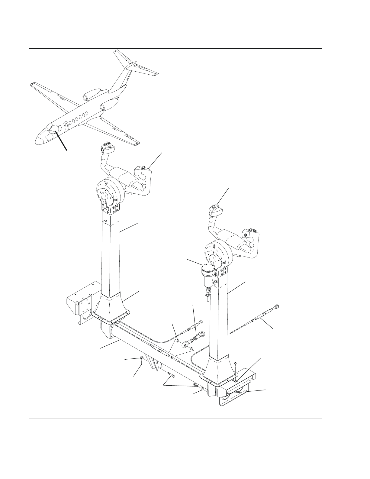
6.ControlColumnRemoval/Installation
NOTE:Pilotandcopilotcontrolcolumnremoval/installationaretypical,exceptasnoted.
A.RemovetheControlColumn(RefertoFigure403).
(1)DisengagePITCHTRIM,AUDIO,XPDR,ANGOFATTACKANDAP(DCandAC)circuit
breakers.Putalabelonthecircuitbreakers:DONOTENGAGE-MAINTENANCEIN
PROGRESS.
(2)Removethepilot'sandcopilot'sseats.RefertoChapter25,FlightCrewSeats-Maintenance
Practices.
(3)Removethescrewsthatattachcontrolcolumnboottocockpitoorboardpanels.
(4)Getaccesstothecontrolcolumnbyremovingcockpitoorboardpanels251BT ,251CT ,251BTC,
251CTC,252CTand252CTC.RefertoChapter6,AccessPlatesandPanelsIdentication-
DescriptionandOperation.
(5)Disconnecttheaileroncrossovercable.Disconnecttheleftandrightaileronforwardcontrol
cables.RefertoAileronandT abSystemControlCables-MaintenancePractices.
(a)RemovetheAileronForwardPulleyBracketandbothleftandrightSupportPlate
Assembliesfromtheaircraft.
(6)Removethecotterpin,nut,washers,andboltthatattachconnectinglinktothetorquetube.
(7)Disconnecttheelectricalconnector(JC303,leftorJF303,right)fromcontrolcolumnwire
bundles.
(8)Removetheboltsandwashersthatattachthetorquetubetothecontrolcolumn.
(9)Movethetorquetubeaftuntilclearofthecontrolcolumns.
(10)Movethecontrolcolumninboardtofreeitfromthebearingsupportandremovethecontrol
columnfromairplane.
27-30-02Page409
©TEXTRONAVIATIONINC.Jul13/2020
ICA-525B-27-00009Form2261Rev1
CESSNA®
MODEL525B
MAINTENANCEMANUAL
DETAILA
COPILOT'S CONTROL WHEEL
PILOT'S CONTROL WHEEL
COPILOT'S
CONTROL COLUMN
STICK
SHAKER
BOOT
PILOT'S
CONTROL COLUMN
TURNBUCKLE
CLIP-ON NUT
BEARING
SUPPORT
WASHER
BOLT
COTTER PIN
NUT
TORQUE TUBE
CONNECTING
LINK
WASHER
A
6310T1072
A6315T1094
A29105
ControlColumnInstallation
Figure403(Sheet1)
27-30-02Page410
©TEXTRONAVIATIONINC.Jul13/2020
ICA-525B-27-00009Form2261Rev1

CESSNA®
MODEL525B
MAINTENANCEMANUAL
B.InstalltheControlColumn(RefertoFigure403).
(1)Putthecontrolcolumninpositiontothebearingsupport.
(2)Movethetorquetubeforwardandattachbothcontrolcolumnstothetorquetubewithwashers
andbolts.
(3)InstalltheleftandrightSupportPlateassembliesandtheForwardAileronPulleyBracket
Assembly.
(4)Attachtheconnectinglinktothetorquetubeusingbolt,nut,andcotterpin.
(a)Installarigpinintheforwardelevatorsector.
(b)Putaninclinometeronthepilotseatrailandzeroit.
(c)Puttheinclinometerontheaftfaceofthepilot'scontrolcolumn.
(d)Adjusttheconnectinglinktogetanangleof92degrees,+0.5or-0.5degreesbetweenthe
aftfaceofthepilot'scolumnandtheoorboards(i.e.columnangleis2degreesforward
ofvertical).
(e)Removetherigpin.
(5)Rigtheaileroncables.RefertoAileronandT abSystemControlCables-MaintenancePractices.
(6)Attachtheaileroncrossovercableandforwardaileroncontrolcable.RefertoAileronandTab
SystemControlCables-MaintenancePractices.
(7)Connectelectricalconnector(JC303,leftorJF303,right)tothecontrolcolumnwirebundle
assembly.
(8)Installcockpitoorboardpanels251BT,251CT,251BTC,251CTC,252CTand252CTC.Refer
toChapter6,AccessPlatesandPanelsIdentication-DescriptionandOperation.
(9)Attachthecontrolcolumnboottothecockpitoorboardpanelswithscrews.
(10)Installthepilotandcopilotseats.RefertoChapter25,FlightCrewSeats-Maintenance
Practices.
(11)Removethemaintenancelabelfromthecircuitbreakerpanel.
(12)EngagethePITCHTRIM,AUDIO,XPDR,ANGOFATTACKandAPcircuitbreakers.
7.ElevatorTrimTabActuatorRemoval/Installation
A.RemovetheTrimT abActuator(RefertoFigure404).
(1)DisengagethePITCHTRIMcircuitbreakerontheleftcircuitbreakerpanel.
(a)Ifpossible,turntheelevatortrimcontrolwheeluntilthetrimtabsarestreamlinedwiththe
elevators.
(2)Getaccesstotheelevatortrimtabactuatorandturnbuckles.
(a)Removethetailconebaggagepanels322BT,322CT,321BBand322BB.RefertoChapter
6,AccessPlatesandPanelsIdentication-DescriptionandOperation.
(3)Removetheelevator.RefertoChapter55,Elevator-MaintenancePractices.
(4)Loosentheelectrictrimcableturnbuckleandthetrimtabcableturnbuckles.
(5)Removethecotterpins,nuts,washers,andboltsthatattachthepushrodstotheelevatortrim
tabactuator.
(6)Removethescrewandspacerfromthechainguardandbendthechainguardawayfromthe
sprocket.
(7)Removethechainfromsprocket.Usetapetoholdthechaintothehorizontalstabilizer.
(8)Removeboltsthatattachtheelevatortrimtabactuatortothehorizontalstabilizer.
(9)Movetheelevatortrimtabactuatorafttoremoveitfromtheairplane.Measureandrecordthe
distancefromthefaceoftheactuatortothecenteroftherodendbearings.
B.InstalltheTrimTabActuator(RefertoFigure404).
NOTE:Iftrimtabactuatorpartnumber6396022-3(left)or6396022-4(right)isinstalled,the
actuatormustalsohaveastainlesssteeltrimcontrolchain(partnumberS3526-25-109)
installed.Thetrimtabactuatorpartnumberisstampedontheactuatorbody.
(1)Lubricatetheelevatortrimtabactuatoratthegreasettingswith5565450-28grease.
(a)Manuallyturnthedrivesprocketoftheactuatoruntilthedistancefromthefaceofthe
actuatortothecenterlineoftherodendbearingsequalsthevalueobtainedbefore.
(2)Puttheelevatortrimtabactuatorinpositionnearthehorizontalstabilizer.
(3)Installtheboltsthatattachthetrimtabactuatortothehorizontalstabilizer.
(4)Installtheelevatorontotheaircraft.RefertoChapter55,Elevator-MaintenancePractices.
27-30-02Page411
©TEXTRONAVIATIONINC.Jul13/2020
ICA-525B-27-00009Form2261Rev1

CESSNA®
MODEL525B
MAINTENANCEMANUAL
6310T1072
A6363T1021
A29106
A
B
B
A
A
DETAIL A(LEFT SIDE SHOWN,
RIGHT SIDE OPPOSITE)
CHAIN
SPACER
SCREW
CHAIN
GUARD
HORIZONTAL
STABILIZER
BOLT
OUTBOARD
ADJUSTABLE
PUSHRODSPROCKET
CABLE
ELEVATOR
TRIM TAB
ACTUATOR
PUSHROD
ELEVATOR
TRIM TAB
HORN
ElevatorTrimTabActuatorInstallation
Figure404(Sheet1)
27-30-02Page412
©TEXTRONAVIATIONINC.Jul13/2020
ICA-525B-27-00009Form2261Rev1
Other manuals for Cessna 525B
1
Table of contents
Other Textron Aviation Aircraft manuals

Textron Aviation
Textron Aviation Cessna 525 User manual

Textron Aviation
Textron Aviation 680A User manual

Textron Aviation
Textron Aviation Cessna 172R NAV III Skyhawk User manual

Textron Aviation
Textron Aviation Cessna 525B User manual

Textron Aviation
Textron Aviation Cessna 172S NAV III Skyhawk SP Quick setup guide

Textron Aviation
Textron Aviation 400T User manual


