Teze 12V200AH User manual

12V200AH
LiFePO4
https://tezepower.com/
(200A BMS)
PRODUCT
MANUAL
Lithium lron Phosphate (LiFePO4)Battery
Originate from TezePower

www.tezepower.com [email protected]m
1
PRODUCT OVERVIEW
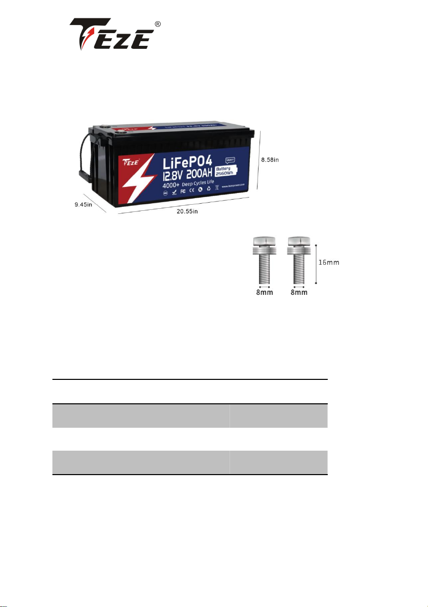
BATTERY
Combination: 12.8V200Ah
Dimension: L20.55*W9.45*H8.58 inch
Plastic Shell Color: Black
TERMINAL & POST BOLTS
Terminal Size:
M8 (1.25mm Metric Thread)
Post Bolts:
M8 (1.25mm Metric Thread*16mm Bolt Length)
(The bolts can be replaced with M8 bolts of other lengths based on actual needs.)
GENERAL INFORMATION
Operating Voltage
12.8V
Charging Voltage
14.4±0.2V
Max Continuous Load Power
2560W
Max Continuous Charge/ Discharge Current
200A
www.tezepower.com [email protected]m
2
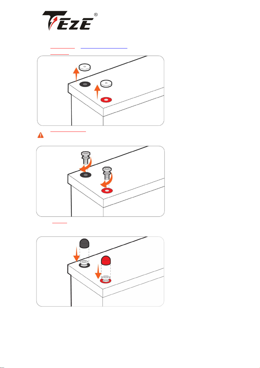
NOTICE BEFORE USING
Step 1:CONTACT US at service@tezepower.com to activate the FIVE-YEAR WARRANTY
Step 2:PULL OUT Insulating Plugs
Step 3: TIGHTLY SCREW IN Post Bolts
Please tightly screw in the post bolts. Having loose battery terminals will cause the terminals to
build up heat resulting in damage to the battery.
Step 4: PUT ON Insulating Covers
Please put on the insulating covers to avoid metal or conductive objects touching the positive and
negative terminals of the battery at the same time, otherwise it is likely to cause a short circuit.
www.tezepower.com [email protected]m
3
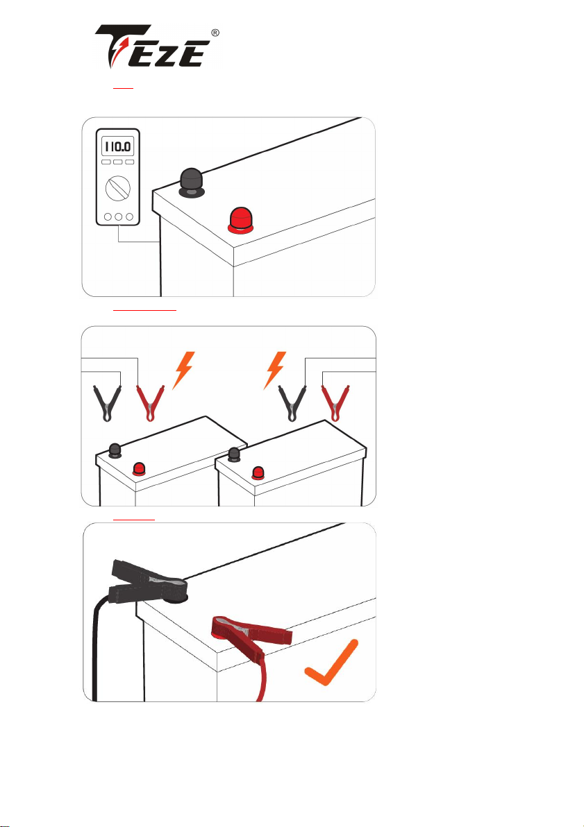
Step 5:TEST The Battery Voltage with Multimeter
≥12V To Step6
<12V Contact us at service@tezepower.com to help solve the problem.
Step 6: FULLY CHARGE The Battery Separately
(Refer to Page 06 for battery charging methods)
Step 7:CONNECT To Use

www.tezepower.com [email protected]m
4
contents
BATTERY- PACK MAIN PARAMETERS .............................................................................5
APP type battery function ............................................................................................. 5
Bluetooth module..............................................................................................................6
Self -heating module..........................................................................................................8
Active equilibrium module (Optional Features)................................................................8
THINGS TO KNOW BEFORE USING ................................................................................ 8
CHARGING METHODS .................................................................................................9
THE VOLTAGE WHEN CHARGING & DISCHARGING...........................................................9
Battery Charging Logic.....................................................................................................10
LiFePO4 Battery Charging Mode..................................................................................... 10
SOLAR PANEL(S) & CONTROLLER.....................................................................................10
Solar Panel......................................................................................................................................................10
Controller ........................................................................................................................................................10
Controller Settings .......................................................................................................................................... 11
BATTERY CHARGER.......................................................................................................... 11
ALTERNATOR/GENERATOR..............................................................................................11
HOW TO ESTIMATE THE BATTERY CAPACITY ................................................................12
STATE OF CHARGE (SOC)................................................................................................. 12
SERIES/PARALLEL CONNECTION .................................................................................. 13
THE PREMISE OF CONNECTION.......................................................................................13
LIMITATION FOR SERIES/PARALLEL CONNECTION..........................................................13
HOW TO CONNECT BATTERIES........................................................................................13
Accessory Recommendation ........................................................................................................................... 13
Step 1 Wear Insulating Gloves ........................................................................................................................14
Step 2 Voltage Balancing Before Connection ................................................................................................. 14
Step 3 Battery-to-Battery Connection .............................................................................................................15
Step 4 Rebalancing Every 6 Months ............................................................................................................... 16
Wiring Diagrams .............................................................................................................................................17
INVERTER SETTINGS ................................................................................................... 19
WHAT TO DO WHEN THE BATTERY STOPS WORKING? ................................................. 20
ATTENTION ................................................................................................................. 21
WARNING ................................................................................................................... 21

www.tezepower.com [email protected]m
5
BATTERY-PACK MAIN PARAMETERS
Cell
Prismatic LiFePO4 Battery
Nominal Capacity
200Ah
Usable Capacity
200Ah
Nominal Voltage
12.8V
Energy
2560Wh
Charge Method
CC/CV
Charge Voltage
14.4V±0.2V
Recommend Charge Current
40A(0.2C)
Battery Management System (BMS) Board
200A
Max. Continuous Charge / Discharge Current
200A
Max. Discharge Current 5 Seconds
400A
Max. Continuous Load Power
2560W
Cycle Life
≥4000 times
Internal Impedance
≤40mΩ
Battery Pack Case
Acrylonitrile Butadiene Styrene (ABS) Plastic
Protection Class
IP65
Weight
45.64lb/20.7kg
Dimension
L20.55*W9.45*H8.58 inch
L522*W240*H218 mm
Temperature Range
Normal-Charge:0C to 50℃/32°F to 122°F
Normal-Discharge:-20℃to 60℃/-4°F to 140°F
Self-Heating Charge: -20℃~50℃/-4℉-122℉
Self-Heating Discharge: -20℃~60℃/-4℉-140℉
Storage:-10℃to 50℃/14F to 122°F

www.tezepower.com [email protected]m
6
APP Type Battery Function (Optional Features)
Bluetooth Module
How to download “Smart BMS” APP
Android:
1. Redirect to download: https://www.dalyelec.cn/daly/SMART_BMS.apk .
2. Redirect to download: https://www.appgallery.huawei.com/#/app/C102450269 .
3. Scan the QR code download below:
Apple:
1. Redirect to download: http://apps.apple.com/cn/app/smart-bms/id1519968339 .
2. Search and Download ‘Smart BMS’ APP in Apple Store.
3. Scan the QR code download below:
Smart APP instruction
1. Once you download “Smart BMS” APP, make sure the Bluetooth in function.
2. Be sure the battery has been activated or follow the included product instruction to activate the
battery.
3. Click “Smart BMS” APP icon to launch.
4. You can see related Bluetooth series number on the APP interface.
5. Click the Bluetooth series number, direct to an interface with real time parameters of voltage,
current, capacity etc.
6. Entering the parameter interface, you will see 5 blocks, including protection, cell, acquisition,
temperature and charge/discharge control.
7. To get stable date, non-professional not recommended to make these setting.
8. Professionals need to use initial password 123456 to set up.


www.tezepower.com [email protected]m
8
Self-heating Module(Optional Features)
Heating power: Use the charger/battery itself to heat. heating
Logic: Connect the charger.
A. When the ambient temperature is detected to be lower than the set temperature (the customer
provides the temperature value), the heating is started and the charge and discharge are
disconnected
B. When the ambient temperature is detected higher than the set temperature (the customer
provides the temperature value), the heating is disconnected and can be charged and discharged
Heating module: Use a separate heating module. It is used separately from the protective plate, but
the heating is controlled by the protective plate.
Active Equilibrium Module
qualification
Data specification
Balance current
0.5~1A
Balance mode
Active equilibrium
Balance on condition
Reach the user-defined opening voltage and
differential pressure
Minimum voltage of single unit ≥ 3.2V (factory
default) and equalizing opening differential
pressure: ≥50mV (factory default)
Balance closing condition
Closing voltage and differential pressure
reaching the user-defined setting
Minimum voltage of single unit <3.2V (factory
default) and equalizing differential pressure: <
50mV (factory default)
Working power consumption
<11mA
Sleep current
300uA
working temperature
-20℃~60℃
Data Monitoring
Bluetooth APP
THINGS TO KNOW BEFORE USING
Always put on the insulating covers on the post bolts to avoid metal or conductive objects
touching the positive and negative terminals of the battery at the same time, otherwise it is
likely to cause a short circuit.
Install the battery upright with post bolt facing up, and it could not be mounted upside
down. If you need to mount the battery at its side, please contact service@tezepower.com to
confirm the direction.
Tightly screw in the post bolts. Having loose battery terminals will cause the terminals to
build up heat resulting in damage to the battery.
This battery is not intended to be used to start any devices, please DO NOT use it as a
starting battery.
www.tezepower.com [email protected]m
9
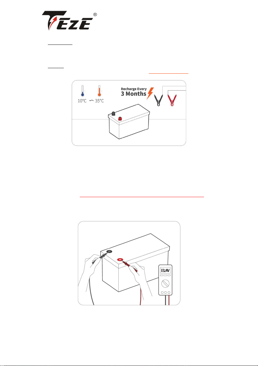
Suggestions for Long-term Storage:
• Temperature
The battery can be operated at a temperature of-20 ℃to 60 ℃/-4°F to 140F, and a temperature
between 10℃to 35℃/50°F to 95°F is ideal for long-term storage. Store in a fireproof container and
away from children.
• Capacity
For a longer-lasting product, it is best to store your battery at a 50% charge level and recharge
every three months if it is not going to be used for a long time.
CHARGING METHODS
THE VOLTAGE WHEN CHARGING & DISCHARGING
Based on the characteristics of Lithium lron Phosphate (LiFePO4) batter- ies, the voltage measured
by all LiFePO4 batteries during charging/dis- charging is not the real yoltage of the battery.
Therefore, after charging/discharging and disconnecting the battery from the power source, the
voltage of the battery will gradually drop/increase to its real voltage.
If you need to test the real voltage of the battery, please disconnect all the connections to the
battery and test its voltage after putting it aside for over 30 mins.
Tips When Testing The Battery Voltage by A Multimeter
①Put the red probe (+) tightly on the positive terminal (not the post bolts), and the black probe (-)
on the negative terminal.
②Do not touch the metal part of the probes with your hands during use.
www.tezepower.com [email protected]m
10
Battery Charging Logic
The material characteristics of the LiFePO4 battery determine that its charging curve is obviously
different from that of a lead-acid battery. Compared with a lead-acid battery, the LiFePO4 battery
has a simpler charging process and mode. Therefore, it is recommended to select LiFePO4 for your
charging mode.
If LiFePO4 mode is not available, please refer to the recommended parameters on Page 10 for
setting.
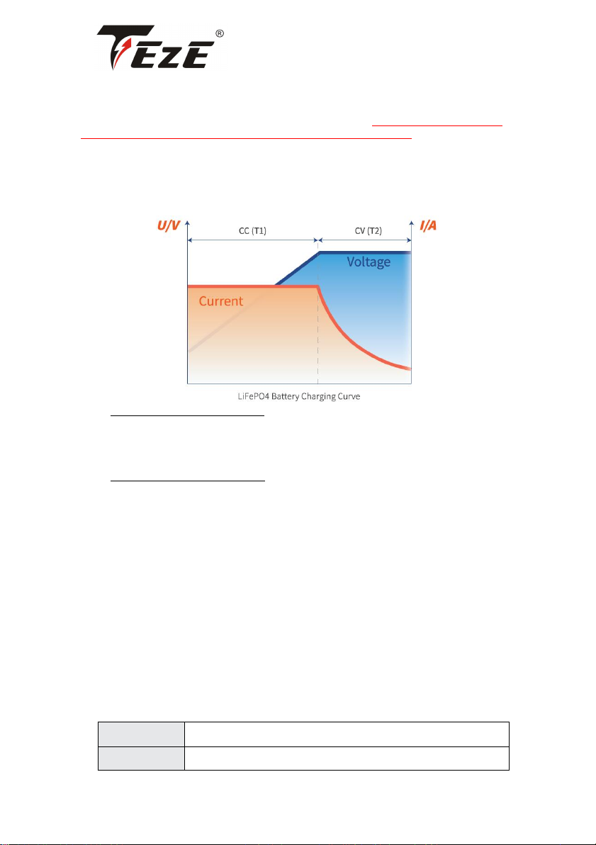
LiFePO4 Battery Charging Mode
•CC (Constant Current) Phase (T1)
In the beginning, a discharged battery will be charged with a constant current and voltage will be
climbing steadily until reaching the constant voltage setpoint which varies for different charging
methods.
•CV (Constant Voltage) Phase (T2)
The battery maintains a constant voltage during this phase while the current gradually decreases to
6A (0.02C) which is also known as tail current. At this point, the charging is cut off and the battery is
fully charged.
SOLAR PANEL(S) & CONTROLLER
Solar Panel
• Recommend Power: ≥900W
• The battery can be fully charged in one day (with effective sunshine 4.5hrs/day) by 900W
solar panels.
• It may take more than one day to fully charge the battery by 900W solar panels since the
duration and intensity of light would be a great factor for their charging efficiency.
Controller
Recommend Charging Current:
40A(0.2C)
The battery will be fully charged in around 5hrs to 100% capacity
100A(0.5C)
The battery will be fully charged in around 2hrs to around 97% capacity
www.tezepower.com [email protected]m
11
Recommend Charging Mode:12V (14.6V) LI (LiFePO4)
Controller Settings
Refer to the below parameters if you need to manually set up your controller.
As different types of batteries have different charging modes (refer to Page 09), it is recommended
to set only the following parameters for LiFePO4 batteries. The settings for other types of batteries
do not apply to LiFePO4 batteries except for the following settings.
CHARGING
charge/Bulk/Boost Voltage
14.4V/14.6V
Absorption Voltage
14.4V/14.6V
Over Voltage Disconnect
15V
Over Voltage Reconnect
14.2V
Tail Current
4A(0.02C)
DIS-CHARGING
Under Voltage Warning
11.6V
Under Voltage Recover
12V
Low Voltage Disconnect
10.8V
Low Voltage Reconnect
12.4V
BATTERY CHARGER
Use 14.6V lithium iron phosphate (LiFePO4) battery charger to maximize the capacity.
Recommend Charging Voltage: Between 14.2Vto 14.6V
Recommend Charging Current:
40A(0.2C)
The battery will be fully charged in around 5hrs to 100% capacity
100A(0.5C)
The battery will be fully charged in around 2hrs to around 97% capacity
Tips
① Connect the charger to the battery before connecting it to the grid power in case of sparks.
② It's recommended to disconnect the charger from the battery after fully charging.
ALTERNATOR/GENERATOR
TEZE battery can be charged by an alternator or generator.
If the alternator/generator supports DC output, a DC-to-DC charger needs to be added between the
battery and the generator; if the alternator/gen- erator supports AC output, please refer to the
recommendations in "Battery Charger" above to add a suitable battery charger between the battery
and the generator.

www.tezepower.com [email protected]m
12
Recommend Charging Voltage: Between 14.2V to 14.6V
Recommend Charging Current:
60A(0.2C)
The battery will be fully charged in around 5hrs to 100% capacity
150A(0.5C)
The battery will be fully charged in around 2hrs to around 97% capacity
HOW TO ESTIMATE THE BATTERY CAPACITY
STATE OF CHARGE (SOC)
The battery capacity could be roughly estimated by its rest voltage (not charging/discharging
voltage). As there are subtle differences in the voltage of each battery, the below parameters are
for reference only.
Rest Voltage : The voltage needs to be tested at rest (with zero current) after 30 mins of
disconnecting from the charger & loads.
CAPACITY
CHARGE VOLTAGE
100%
13.5V
99%
13.4V
90%
13.3V
70%
13.2V
40%
13.1V
30%
13.0V
20%
12.9V
10%
12.8V
1%
10.8V(recommend low voltage disconnect voltage)
0%
9.5V

www.tezepower.com [email protected]m
13
SERIES/PARALLEL CONNECTION
THE PREMISE OF CONNECTION
To connect in series or/and parallel, batteries should meet the below conditions;
a. identical batteries with the same battery capacity (Ah) and BMS (A);
b. from the same brand (as lithium battery from different brands has their special BMS);
c. purchased in near time (within one month).
LIMITATION FOR SERIES/PARALLEL CONNECTION
Support connecting up to 16 identical batteries for up to
4 in series as 48V (51.2V) battery system/
4 in parallel as 1200Ah battery system.
HOW TO CONNECT BATTERIES
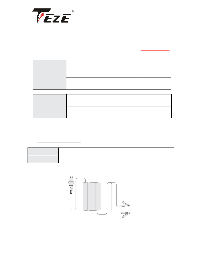
Accessory Recommendation
Battery-to-Battery Connection Cable: 2*6AWG Copper Cable
Total Input & Output Connection: Adding two copper bars except for the cables.
Step 1:Refer to Page 14-16 to finish your battery-to-battery connection.
Step 2:Connect all the positive output cables of the batteries to one copper bar.
If the positive (+) of the battery is connected to the negative (-) of other batteries (i.e. in series

www.tezepower.com [email protected]m
14
connection), the + cannot be connected to the copper bar, otherwise the battery system will fail to
connect in series.)
Step 3:Connect the of the load to the copper bar.
The cable gauge used in this step should be able to support the total input & output current of
the entire battery system.
Step 4:The of the battery system and load are also connected to another copper bar
following the above steps.
Step 1 Wear Insulating Gloves
Wear Insulating Gloves for protection before connecting. Please pay attention to operation safety in
the process of connection.
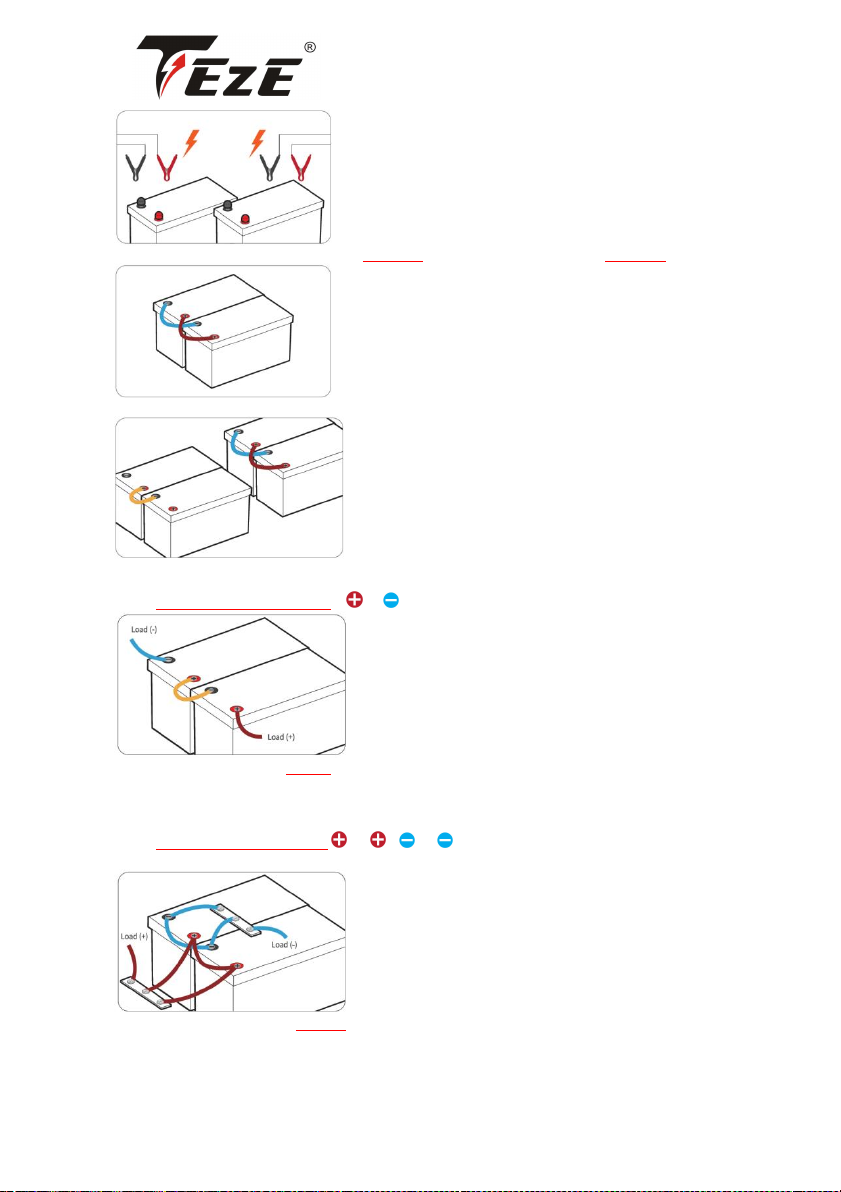
Step 2 Voltage Balancing Before Connection
Below two steps are necessary to reduce the voltage difference between batteries and let the
battery system perform the best of it in series or/and in parallel.
• Fully charge the batteries separately
(voltage at rest: ≥13.4V)
www.tezepower.com [email protected]m
15
• Connect the batteries one by one in parallel, and leave them together for 12~24 hrs.
• They can then be connected in series or parallel.
Step 3 Battery-to-Battery Connection
Connect Batteries in Series to
After series connection, the voltage of the battery system will be doubled according to the number
of batteries you connect.
E.g. If two 12V 200Ah batteries are connected in series, the battery system will be 24V (25.6V)
200Ah.
Connect Batteries in Parallel to to
Refer to Page 11 for total input & output connection
After parallel connection, the capacity of the battery system will be doubled according to the
number of batteries you connect.
E.g. If two 12V 200Ah batteries are connected in parallel, the battery system will be 12V (12.8V)
400Ah.
www.tezepower.com [email protected]m
16
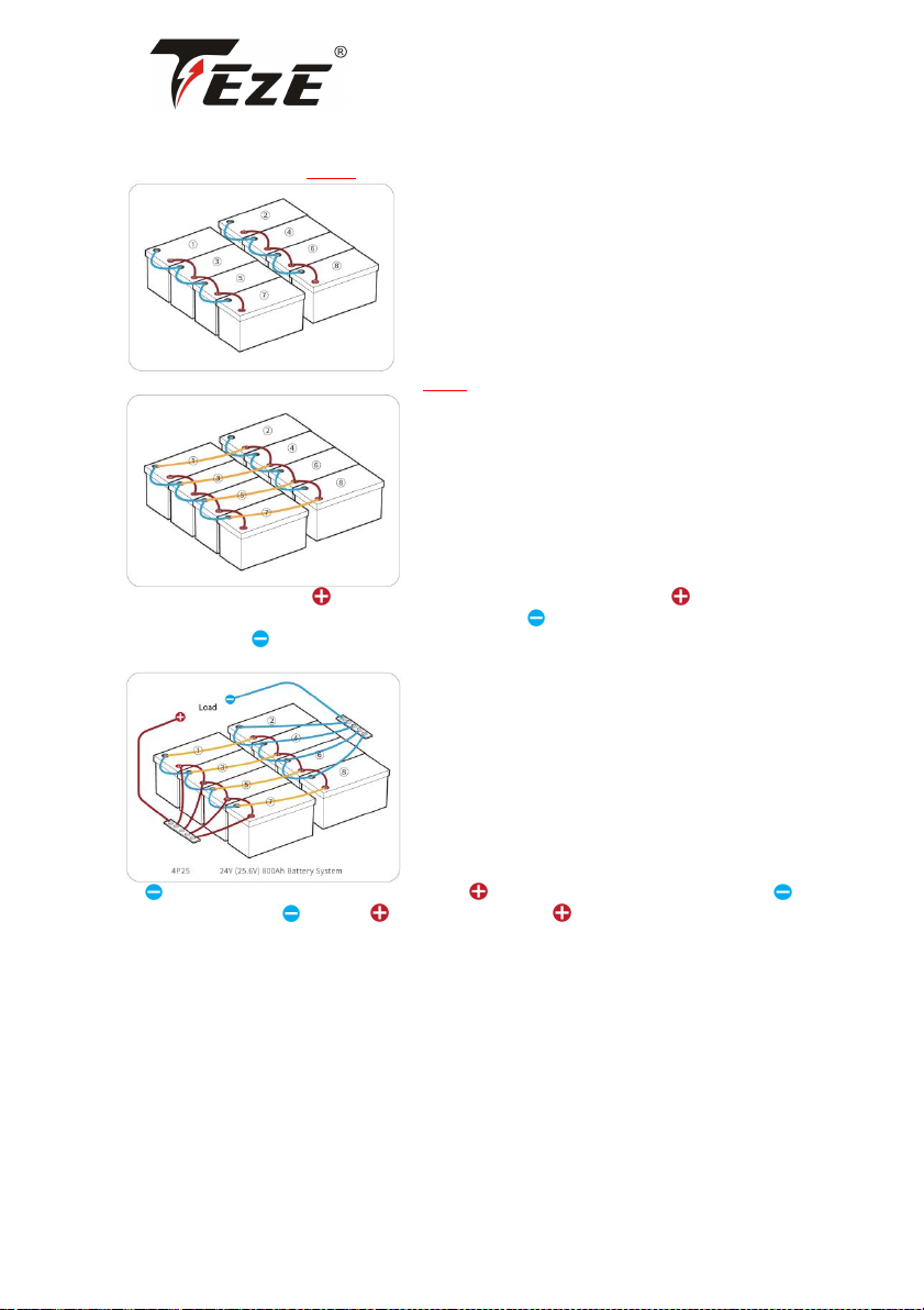
Connect Batteries Both in Series & Parallel
Optimal Connection Method Recommendation
1. Connect the batteries in parallel
2. Connect the paralleled battery systems in series.
Connect the positive of battery①/③/⑤/⑦ to a copper bar and the of the load to
the same copper bar. And then connect the negative of②/④/⑥/⑧ to another copper
bar and the of the load to the same copper bar.
Refer to Page16-17 for 2P2S, 2P4S battery system wiring diagram
As of①/③/⑤/⑦ is connected in series with of ②/④/⑥/⑧, please do not connect
of①/③/⑤/⑦ with of load or of ②/④/⑥/⑧ with of load, otherwise the battery
system will fail to connect in series.
Step 4 Rebalancing Every 6 Months
It is recommended to rebalance the battery voltage every six months following Step 2 on Page 13 if
you're connecting multiple batteries as a battery system, as there might be voltage differences after
six months of the battery system
running.

www.tezepower.com [email protected]m
17
Wiring Diagrams
2S2P
Battery System
24V(25.6V)400Ah
Energy
10,240Wh
Max. Continuous Charge / Discharge Current
200A
Max. Continuous Load Power
5120W
2P4S
Battery System
48V (51.2V)400Ah
Energy
20,480Wh
Max. Continuous Charge / Discharge Current
200A
Max. Continuous Load Power
10,240W

www.tezepower.com [email protected]m
18
4P2S
Battery System
24V (25.6V)800Ah
Energy
20,480Wh
Max. Continuous Charge / Discharge Current
200A
Max. Continuous Load Power
10,240W
·
Table of contents
Other Teze Batteries Pack manuals


