TFC Boiler Plus Optimum Vibe User manual
OPTIMUM VIBE PROGRAMMABLE THERMOSTAT - INSTALLATION INSTRUCTIONS
The OPTIMUM VIBE is a radio frequency programmable thermostat. It MUST be installed by a qualied person, in
accordance with best pracse and current IEE wiring regulaons. Before programming, complete all set-up instrucons.
The control set - when congured for T.P.I. control - meets the UK Government BEIS Department’s criteria for Class
IV control, contribung 2% towards energy eciency of the system.
The transmier is baery-powered (2 x AAA alkaline); the receiver is mains-powered, with volt-free switching.
The control set uses the license - free 868 MHz radio band to communicate between transmier and receiver
Installaon procedure: transmier and receiver posioning
The receiver will normally be located close to the heat source, and should derive it’s mains supply from the same
circuit that powers the heater / boiler. However avoid locang it directly next to the boiler’s case - see 1 below.
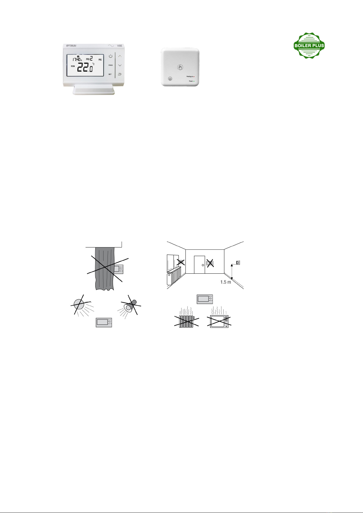
The transmier should be located within the property bearing in mind the following requirements:
The transmier has an on-board temperature sensor, which it uses to detect ambient temperature, and calculates
whether to send a demand or no-demand signal to the receiver. The transmier should be located in a main living
area, where it is visible, has a free air-ow and is not unduly inuenced by draughts or extraneous heat sources:
radiator / direct sunlight / lamp— please refer to the diagrams below:
1 The radio-frequency signal range is 20 to 30 metres in convenonal brick / mber / le structures. Note that me-
tallic materials such as reinforced concrete and foil-backed plasterboard will reduce or in some cases block the ra-
dio frequency signals. It is best to posion both transmier and receiver so that they are not close to large metallic
objects, and bear in mind that mirrors reect radio waves in the same way they reect light.
Transmier - installaon
Place 2 x AAA alkaline baeries in the baery compartment at the back of the transmier; ensure correct polarity.
Set the me and day: Aer inserng baeries, the transmier will jump to me-seng mode, or during normal
operaon, touch SET for ve seconds, change the minutes, touch SET, change the hours, touch SET, change the
day, touch SET. Then touch the ON/OFF icon to put in run mode. Full set-up can be completed later.
The transmier can be wall-mounted, or placed on a table-top or counter, using the back-plate or the stand includ-
ed in the carton. If wall-mounng, x the back-plate to the wall observing the UP ↑ ↑ marks, align the top two
recesses on the back of the transmier, to the top two lugs on the back-plate, then rotate downwards to ‘click’ the
other two lugs in place. Reverse this procedure to remove the transmier from the back-plate. Note that - if you
hold the transmier for longer than a few seconds, it will start to detect your body temperature, rather than the
ambient room temperature, and this will aect the calculaon of demand / no demand for heat. Replace the
transmier onto the back-plate or stand so that it will again start to detect the ambient room temperature.
Transmier Receiver
Receiver - installaon
The receiver is intended for wall-mounng in a clean, dry environment. It is a class II control,
suitable for ambient temperature from 0 to 500C. It has 60mm wall-xing centres which are com-
pable with standard paress boxes. A back-plate channel is provided if wiring has to be surface-run.
The receiver requires a 230 volt live and neutral supply, and controls a volt-free changeover switch.
Separate the receiver top cover from the base by gently levering the cover upwards with a at-bladed screwdriver
placed into the two slots on the underside.
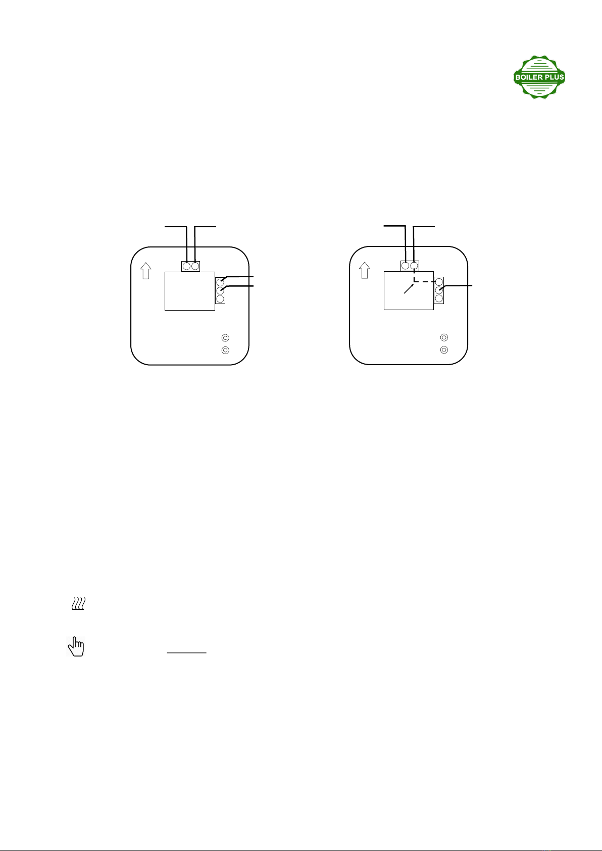
Fit the receiver to the wall, and connect to the terminals provided. See the wiring diagrams below:
N
AC230V L
COM
N O
N C
UP
Neutral Live
SW1
SW2
N
AC230V L
COM
N O
N C
UP
Neutral Live
Switched
Live
Link
Wiring for volt-free switching:
Connect 230V AC Live and Neutral to L & N
Connect the volt-free boiler connecons
(SW1 / SW2) to COM & N O (common and
normally open)
Do not connect anything to terminal N C
Wiring for mains switching:
Connect 230V AC Live and Neutral to L & N
Fit a short link wire between L & COM
Connect the (230V mains) switched live to N O
Do not connect anything to terminal N C
The VIBE receiver is a double-insulated Class II control. No earth connecon is needed. Use a separate single
screw terminal block to provide earth connuity if required. Clip the cover on top of the installed receiver: align the
two lugs on the upper edge of the cover with the tabs on the base, and pivot downwards, applying light pressure
unl the housing clicks into place.
Power-up the control set and complete the seng up procedure.
Aer ng baeries to the transmier; ng the receiver to the wall and installing wired connecons appropri-
ate for the heang appliance, switch on the mains supply to the receiver. The green Power L E D should be visi-
ble on the receiver. Now check the receiver response: keep the transmier approximately 1 to 2 metres from the
receiver, and touch the UP arrow to raise the SET temperature above the measured ROOM temperature. Within
2 or 3 seconds the demand symbol (see le) should appear in the display, and within a further ~10 seconds, the
receiver Heang on LED should illuminate. There is an audible click as the switching relay operates. The heang
appliance should now be running. The receiver can also be operated manually by briey pressing the centre
override buon. Note that if the transmier is le in demand mode aer the receiver is manually overridden to
o (and vice-versa), the transmier will re-assert control and switch back on approximately 10 minutes later.
The transmier and receiver control set is pre-commissioned at the factory. Refreshing of the RF link is possible
(see Refresh RF Link on page 4), but this should not be necessary. The transmier and receiver should communi-
cate as soon as they are both powered-up. If there is a problem, make sure that:
- the green Power LED on the receiver is illuminated. If not, check the mains supply and ensure the receiver is on.
If necessary, briey press the receiver ON/OFF buon.
- the demand symbol is visible in the transmier’s LCD. If not, increase the SET temperature to at least one de-
gree above the ROOM temperature. The demand symbol should be visible within three seconds of seng a de-
mand temperature.
Before connecng the receiver to the boiler, make sure that you have followed the boiler external thermostat
connecon instrucons. A mains connecon to a volt-free terminal could damage the boiler circuitry.
To open the conguraon menu, rst touch the transmier ON/OFF buon to turn the display o (touch
any buon to ‘wake-up’ the transmier, then touch the ON/OFF buon to turn o), then touch the SET and
UP buons at the same me for 5 seconds:
You will be viewing the rst of 15 opons which can be congured to adjust the operaon of the OPTIMUM
VIBE, to best suit the installaon and the user’s requirements.
Touch the UP or DOWN arrows to adjust the parameter, and touch SET to move sequenally through the
opons. Changes will be saved by pressing the ON/OFF buon. If no buon is touched for 10 seconds, the
display will ‘me-out’, but your changes will sll be saved.
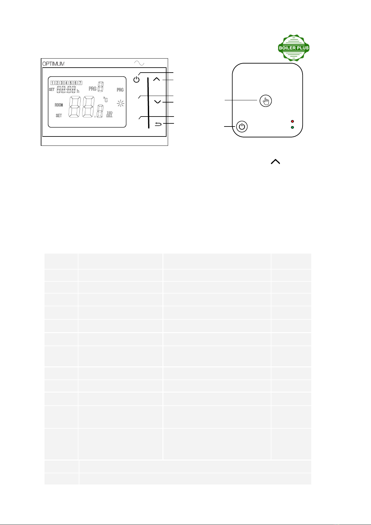
Transmier and receiver display / controls
Assuming the receiver response is O.K., proceed to the rest of the seng-up procedure.
SET
Parameter seng — how to congure the way your Opmum Vibe thermostat works: +
Opon Descripon Range Default value
01 Temperature calibraon -80C ~ +80C00C
02 Maximum temperature seng 50C ~ 350C350C
03 Minimum temperature seng 50C ~ 350C50C
> 05 Frost-protecon temperature OFF (- - in cong. Screen), or 50C ~ 150C50C
09 Hysteresis (dierenal) 0.50C ~ 3.50C0.50C
> 10 Display seng 0 ~ 1 0
17 Reset (reset all values to
factory default)
Change to 1. Then touch Power buon
for 5 seconds
0
18 Firmware code Non adjustable * 5091
19 Firmware code Non adjustable * 0202
50 Backlight 0: OFF 1: AUTO 1
> 51 Programme mode 76: 7 days / 6 periods
526: Weekday / Weekend / 6 periods
526
> 52 Temperature regulaon mode NOr: Normal (ON/OFF)
OPs: Opmum Start
tPi: Time Proporonal / Integral
NOr
Power
Heang on
OVERRIDE
(short press)
RF LINK
(long press)
ON/OFF
Receiver
VIBE
ON/OFF
UP
PROGRAM
DOWN
SETTINGS
BACK
PROG
SET
Transmier
>See addional notes about these conguraon opons on Page 4
*Firmware is pre-loaded in the factory, and visible for reference but cannot be changed.

Refresh RF link
Press and hold the centre override buon on the receiver unl the Heang on LED ashes rapidly. Release the
override buon—the LED must be ashing. Turn o the transmier by touching the ON/OFF icon. The display
will go blank. Now touch the SET icon for 5 seconds. A unique pre-set four-character code will show in the top
le of the display. Release and then briey touch the SET icon once more. The receiver LED will stop ashing and
the RF link has been refreshed. Quit back to normal running mode by touching the ON/OFF icon.
Receiver ON / OFF
You can turn o the receiver. The receiver’s output will switch o, and it will stop responding to the transmier.
Transmier ON/OFF
You can save baery power on the transmier, by touching the ON/OFF icon. The transmier is switched o and
will stop sending control signals; the receiver will remain in it’s current state (ON or OFF).
Specicaon:
868 MHz radio frequency control set, with 4 character hexadecimal coding giving 65,536 code combinaons.
Transmier power 2 x AAA alkaline. Touch-screen keys. 70 x 40mm backlit LCD. Dimensions 120 x 85 x 22.5mm
Receiver power 230V AC, volt-free changeover 10A (resisve) switching, ON/OFF & manual override buons. Di-
mensions 85 x 85 x 25mm. Wall-xing centres 60mm.
Set control features: 20—30m range in buildings. ON/OFF, Opmising & TPI temperature regulaon. Hysteresis
+/- 0.50C. 5 & 2 or 7 day programming. 6 me / temperature periods. Temperature range 5—35 0C.
Boiler Plus compable: Class IV control, 2% contribuon to system eciency
Approvals: CE - Radio Equipment Direcve EN 2014/53/EU - RoHS
Do not dispose of this product with household waste - use local recycling facilies
Opon Descripon Range Default value
> 53 Time interval for Ops 10 min, 15 min, 20 min 20 min
> 54 Number of heang cycles/hour (for TPi) Range: 2 ~ 3 ~ 6 ~ 12 6
> 55 Proporonal Bandwidth (for TPi) Range: 1.50C— 30C20C
Conguraon opons—addional notes:
Opon Descripon
05 If you set a frost-protecon temperature, the heang will be switched on when the
measured temperature falls below this level, even if the transmier has been turned o.
10 0 - (default) Room and Set temperatures displayed. 1 - only Set temperature displayed
51 76— you can set every day with a dierent programme
526—two programme sequences can be set, one for weekdays, one for weekends. The fac-
tory default programme shown in the user instrucon is the default programme for both.
52 Please read ‘how it works’ for a full explanaon of temperature regulaon modes
53 Set if you chose OPs (Opmum Start) regulaon. For the best results, the me interval se-
lected should approximate the me taken to increase the room temperature by 1 degree.
54 Set if you chose TPi regulaon. Select a lower number for heang systems with a slow re-
sponse, and a higher number for heang systems with a fast response.
55 Set if you chose TPi regulaon. Sets the temperature below the set-point at which TPi con-
trol will begin
QR058 Prepared for TFC Group by: J. Todd Issue 3: June 2019
Table of contents
Other TFC Thermostat manuals


