TFC RF205-TS User manual

RF205 Series
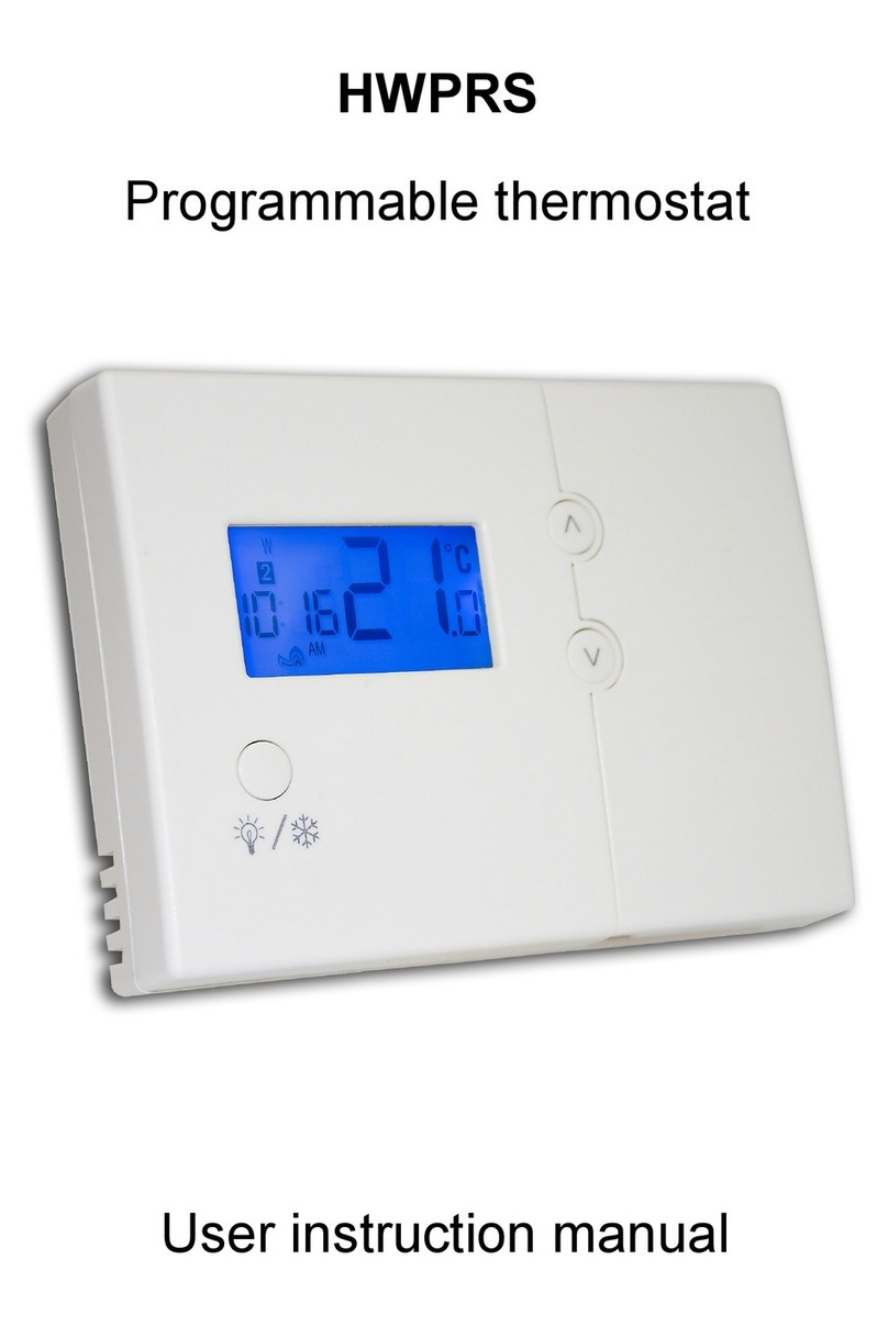
Programmable RF room thermostat
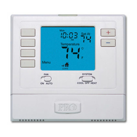
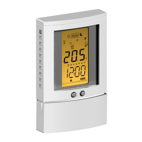
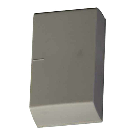
RF205-TS programmable room thermostat (transmitter) T55 (Receiver)
1. General
The RF205-TS is a radio controlled room thermostat which requires no wiring and is designed to be fitted in a
conventional household installation, at a maximum 30 metres range of the T55 “boiler module”, which is a
boiler-mounted modular receiver.
The T55 receiver must be installed by a qualified installation engineer. Do not place it too close to objects
which might interfere with the radio signal. It is preferable to mount the receiver such that an imaginary
straight line between it and the transmitter thermostat is not obscured by the boiler or any other large metal
objects such as kitchen appliances. When installing these devices, please avoid touching the PCB as static
damage can occur.
The RF205 control set has already been commissioned, or matched, in the factory. Just connect power to the
receiver / put batteries in the transmitter, and the set will communicate. If for any reason you wish to verify
the RF link please refer to the fourth option under section 7. Configuration Setting
2. Technical data
Operating voltage: receiver: 230VAC ± 10%; transmitter: 3.0V ± 0.2 V DC
Time regulation: < 3s/Day Transmitter power supply: 2 x AA alkaline
Consumption: <0.06W Set-point range: 5.0ºC - 35.0ºC
Accuracy: ±0.5ºC Load current: 2A
Thermostat size: 136mm x 90mm x 30mm Receiver size: 60mm x 60mm x 32mm
3. T55 receiver fitting and wiring
RF205 BM(EN) V1 2016-11-15
Transmitter link via RF Frequency: 433MHz
LED indicator for matching/output status
Recessed button for RF matching
Connections:
1 –Neutral input
2 –Live input
3 –Common input
4 –Normally open output

RF205 Series
Programmable RF room thermostat
4. Installation instructions
1) Loosen the screws on the underside of the
RF205-TS.
2) Release the top half of the housing (there is a
small clip adjacent to the battery compartment)
and open the device. Be careful not to touch the
PCB, in case of static discharge.
3) Please use two screws (provided) to fasten
the rear housing of the LCD unit on the wall or
box. Several fixing points are provided, including
two on 60mm pitch for a standard wall box.
4) Replace the top housing of the device.
5) Press lightly to close, and tighten the screws.
6) Put two AA batteries into the compartment,
observing the polarity markings, and slide the
cover into position.
5. Keys and function instruction
Power on/off –press briefly to switch the device ON or OFF
Manual Mode.
Programme Run Mode.
Economy –press briefly for Economy mode. Press to restore Programme Run Mode
Time adjustment. Press the key in sequence: minute-hour-day.
Programme entry Mode - Press the key to access programme setting.
Confirm. Press the key to confirm the setting parameters.
In Programme Run and Manual mode: temperature increase. In Programme Entry Mode: hour,
minute or temperature increase.
In Programme Run and Manual mode: temperature decrease. In Programme Entry Mode: hour,
minute or temperature decrease.

RF205 Series
Programmable RF room thermostat
6. Menu & setting
6.1. Temperature setting.
Press or once, the backlight will turn on. Then Press to increase the set temperature, or
press , to reduce the set temperature. From Programme Run Mode, this will initiate Temporary Manual
Mode, which will revert to Programme Run Mode at the next timed setting. See 6.4 below.
6.2. Manual mode setting
Switch to manual mode by pressing . The hand symbol will be displayed on the LCD screen.
Having selected Manual mode you can set a fixed temperature. Manual Mode is a permanent selection.
6.3. Weekly Programme Run mode setting
Switch to Programme Run Mode by pressing . The symbol will be displayed on the LCD screen and
the automatic programme will operate.
6.4. Temporary manual mode setting
During Programme Run Mode, press or once to turn on backlight (to prevent misoperation), and
press or again to check the set-point in the current period of Weekly programming mode. Then
press or to set the desired temperature for the Temporary Manual Mode. If both symbols
are visible in the display, the device is in Temporary Manual Mode.
The thermostat runs according to the manually set temperature during Temporary Manual Mode, and
returns to Weekly Programme Run Mode at the next period start time (the temperature set in Temporary
Manual Mode is not stored).
6.5. Confirmation key
At any time while programming, press to confirm programming, changed data is stored, and the
device will revert to Weekly Programme Run Mode.
6.6. Economy key
Press the ‘moon’ button to switch to economy mode. The moon symbol will show in the display. In
Economy mode you can set the temperature value to a lower ‘economy’ level to suit your requirements –
e.g. 8 / 10 / 12 degrees –using the or buttons. Press the button to go back to the normal
Programme Run mode.
6.7. Clock Setting
Press to set minute, hour and week. Press and to change the flashing value. Press to
move to the next step, or press to confirm.
6.8. 5+2 Day programmable schedule setting
Press to enter the Weekly programming mode setting. Press and to adjust the parameters.
After setting each parameter, press to store your change and select the next parameter.
Programming is in the following sequence: (icons representing the six available programme spaces can be
seen at each step on the right-hand side of the screen) –for example:
Start time (hours, then minutes) setting of 1st period of Monday to Friday morning →
Temperature setting of 1st period of Monday to Friday morning →………..→
Continue with the same sequence to set the remaining time / temperature requirements for Monday to
Friday. You will then reach Saturday / Sunday settings. Continue until you complete the temperature
setting of 6th period of Saturday & Sunday. Or if you have completed programme changes mid-way
through the sequence, press to confirm changes and return to Run mode.
Please follow the sequence below to view and (if required) adjust each time and temperature set-point.

RF205 Series
Programmable RF room thermostat
7. Configuration Setting
Enter into Configuration Setting by pressing briefly during Power-off Status. Then press sequentially to
view and amend (if required) parameters noted below.
You can confirm any changed parameters by pressing . Press the Power Button to exit configuration.
Display symbols
Options Properties
Remark
01
Inside sensor temperature
correction
Range: -9 to +9℃
Press ▲ or ▼ for adjustment.
02
Temperature differential
Range: 1 –5 ℃Press ▲ or ▼ for adjustment.
03
5+2 days, 6+1 days or 7
days programmable
schedule selection
A1: 5+2 days programmable
A2: 6+1 days programmable
A3: 7 days programmable
Press ▲ or ▼ to select A1, A2 or A3.
00 or AA
Display IP address XX XX
To refresh the RF matching. When power is connected, press
and hold the Recessed button in receiver for 5 seconds, the LED
indicator will be flickering for 10 seconds. During the period of
flicker, select OO / AA configuration display (Keep transmitter
close to receiver), press for matching.
OO: waiting for match. AA: matched already.
The receiver’s IP code (printed on the side of the receiver) is
shown in the lower right-hand corner of the LCD.
RS
Reset to factory setting
Press for 5 seconds to reset schedule
8. Warranty
This product has 12 months warranty from purchase date. Malfunctions due to mis-use or mis-application are
not covered by the warranty.
9. ErP Directive (EU regulation no. 811/2013)
ErP Class I : Contribution to system energy efficiency: 1% On/off room thermostat: A room thermostat
that controls the on/off operation of a heater. Performance parameters are determined by the thermostat’s
mechanical construction.
This manual suits for next models
2
Other TFC Thermostat manuals
