7
3. Technical parameters
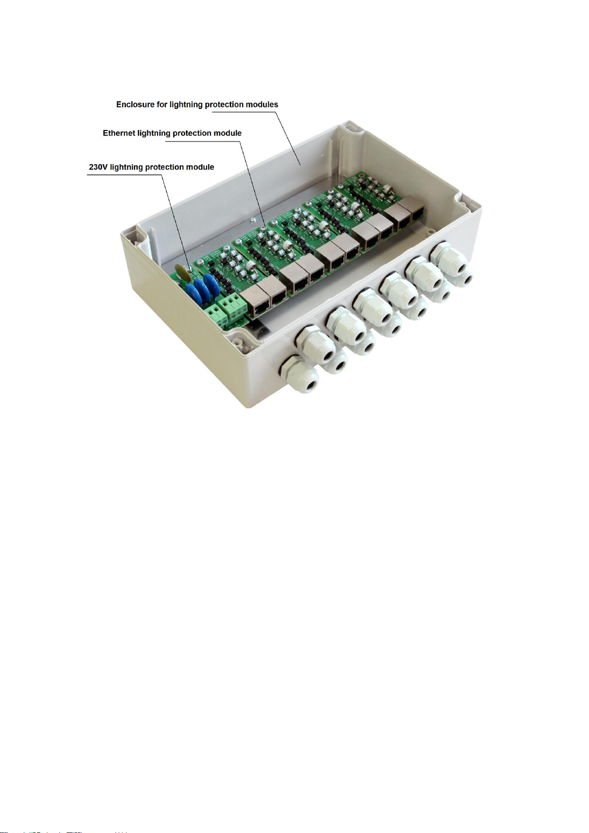
TFortis SG-Switch lightning protection device
Dust and moisture protection –IP66.
Number of modules –6.
Number of cable glands –13 (PG9).
Grounding pin –M4
Dimensions 240x160x90 mm.
Maximum weight –2 kg.
Ethernet lightning protection module (ESG)
Supports 10/100/1000Base-T
Supports IEEE802.3af/at (including 60W)
All conductors are protected by the twisted pair
Protects Ethernet ports of TFortis PSW switches from powerful pulse
interferences –4 kV, 6.5/700 µs based on the «wire-ground» scheme
with performance criterion B (GOST R 51317.4.5)
230V power supply lightning protection module (PSG)
Protects 230 VAC power supply circuits of TFortis PSW switches
from powerful pulse interferences –4 kV, 1/50 µs based on the «wire-
wire» and «wire-ground» scheme with performance criterion B
(GOST R 51317.4.5)
Terminal block for the screw
Maximum cable section is 2.5 sq. mm.