TFortis PSW-2G2F+UPS User manual

Operating Manual
PSW-2G2F+UPS
Multifunction Gigabit Managed Switch
with built-in UPS for connection to IP video cameras that
support IEEE802.3at.
Version 5

!
!
!
Elements of the power units are under high
voltage. It is strictly forbidden to touch conducting
elements of the power supply unit under voltage.
It is forbidden to transport the switch with the
battery installed in it.
It is forbidden to connect very low battery (voltage
at the terminals below 9.6V)
SFP port operates only at 1000 Mbps. Fast Ethernet
SFP modules will not operate.
2

Contents
1. Purpose.....................................................................................................4
2. Description................................................................................................6
2.1. Appearance........................................................................................6
2.2. Components layout ............................................................................8
2.3. PoE power supply..............................................................................9
2.4. Lightning protection..........................................................................10
2.5. Restarting cameras in case of hanging ...........................................11
2.6. Cable tester......................................................................................11
2.7. Remote camera polling....................................................................12
2.8. Built-in UPS......................................................................................12
2.8.1. Control of incoming voltage.......................................................12
2.8.2. Description of UPS operation....................................................13
2.8.3. Estimation of uninterrupted operation time ...............................15
2.8.4. Battery function check...............................................................16
2.8.5. Battery installation.....................................................................16
2.8.6. Control of fans operation...........................................................17
3. Technical parameters .............................................................................18
4. Operating conditions...............................................................................18
5. Preliminary setting ..................................................................................19
5.1. Resetting the switch to factory settings ...........................................19
5.2. IP address setting ............................................................................19
5.3. User name and password setting ....................................................20
5.4. Activation of redundancy protocols..................................................20
6. Installation of the switch..........................................................................21
6.1. Mounting of the housing...................................................................21
6.1.1. Wall mounting............................................................................21
6.1.2. Mounting on the pole.................................................................21
6.1.3. Installation into TFortis CrossBox cabinet.................................21
6.2. Optical connections..........................................................................23
6.3. Power supply connection.................................................................23
6.4. Camera connection..........................................................................24
7. Manufacturer's warranty .........................................................................25
3
1. Purpose
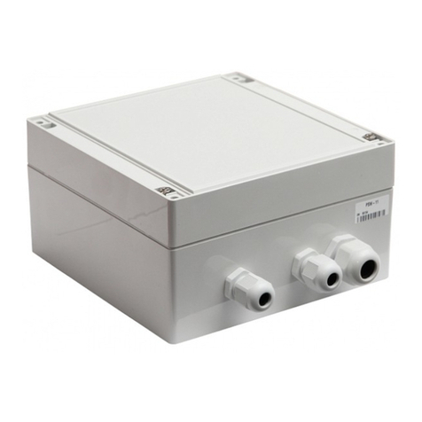
PSW-2G2F+UPS device is a multifunction gigabit outdoor managed switch
with built-in UPS designed for connecting IP video cameras with
IEEE802.3at (PoE+) support
one camera with 60W power consumption (Figure 1-1)
two cameras with 30W power consumption each (Figure 1-2)
Figure 1-1. Connection scheme for one 60W camera.
Figure 1-2. Connection scheme for two 30W cameras.
4

Weatherproof design
The switch body is made of technopolymer resistant to severe operating
conditions. Dust and moisture protection rating is IP66. It is possible to
operate the device without additional enclosures.
Operation is a wide temperature range
The device is manufactured from industrial-type components and does not
need additional heating. The exceptions are batteries that are heating using
two heaters, which ensures operation of the device in the range from - 45
to +40C.
High performance gigabit switch
The key element of the switch is high performance chip from Marvell, which
is able to process a large volume of traffic coming from the IP cameras.
PoE+ support for one port up to 60W
The switch supports IEEE802.3at power supply. Power can be supplied
either by pairs with data (pairs 1,2 and 3,6), or by free pairs (pairs 4,5 and
7,8) simultaneously. As a result, 60W can be supplied to the camera
(30W+30W).
PoE+ support for two ports, 30W each
The switch can support operation of two ports with 30W power for each
port.
Uninterrupted power supply for the whole system
Because the switch is equipped with UPS and cameras can be supplied by
PoE, the whole system has power backup.
Withstands the voltage of 380V
When 380V voltage is supplied to the switch, it will be supplied from the
battery and the whole system will continue to operate from the reserve
power supply.
Connection to 220V
A built-in power supply unit ensures direct connection of the switch to 220V
power supply, eliminating the need for additional power supply unit.
Lightning protection
A built-in lightning protection for Ethernet ports and 220V power supply
protects the switch and connected cameras from surges caused by
electrostatic discharges.
5

Automatic restart in case of camera hanging The switch controls
operation of the video camera. In case of hanging, the switch will restart the
camera automatically over PoE. It allows to create unattended IP video
surveillance networks.
Operation in a ring or in a chain configuration
Two gigabit ports allow to connect switches in a chain. Support of
STP/RSTP protocols allow to create ring topologies, which significantly
improves fault tolerance of the system.
2. Description
2.1. Appearance
Figure 2.1-1. PSW-2G2F+UPS switch, external appearance
6

Figure 2.1-2. PSW-2G2F+UPS switch, internal appearance
7

2.2. Components layout
Figure 2.2-2. Layout of components in PSW-2G2F+UPS switch
During normal operation, CPU indicator should blink intermittently with 2
sec. period (1 sec. –ON, 1 sec. –OFF). DEFAULT indicator shall be ON,
when the device operates with factory settings (IP 192.168.0.1).
8

2.3. PoE power supply
PSW-2G2F+UPS switch supports IEEE802.3at power supply. The switch
can supply
either one camera with 60W power consumption (by default)
or two cameras with 30W power consumption each
Port 1 (60W)
Power is supplied by pairs 1,2 and 3,6 over data, and by free pairs 4,5 and
7,8 simultaneously. This way of power supply is implemented in powerful
video cameras with power consumption up to 60W.
60 W
PSW-2G2F+UPS
Pairs 1,2 and 3,6
IEEE802.3at
Pairs 4, 5 and 7, 8
IEEE802.3at
Figure 2.3-1. Power supply scheme over PoE+ (60W)
WARNING! For operation with BEWARD cameras that support UltraPoE,
this mode has to be activated in the switch via WEB interface (see
Configuration Manual).
Port 2 (30W)
Power is supplied via pairs 1, 2 and 3, 6 over data.
30 W
PSW-2G2F+UPS
Pairs 1,2 and 3,6
IEEE802.3at
Figure 2.3-2. Power supply scheme over PoE+ (30W)
WARNING! First switch port 1 to 30W mode, then activate PoE on port 2
(see Configuration Manual).
9

2.4. Lightning protection
PSW-2G2F+UPS switch has built-in lightning protection modules that
protect Ethernet ports and 220V power circuits from common-mode and
differential electromagnetic interferences.
The switch is resistant to powerful microsecond pulse interferences
according to GOST R 51317.4.5 standard with the degree of severity
according to Table 2.4-1, performance criteria B.
The switch is resistant to AC transients in the power supply circuit
according to GOST R 51317.4.11 standard, Table 2.4-2, performance
criteria B.
Table 2.4-1.
port
Degree of severity according to
Table 1 GOST R 51317.4.5
Voltage pulse
value, kV + 10%
Power supply lines
3
2
“wire-to-wire”
Power supply lines
4
4
“wire-to-ground”
Symmetrical communication lines
3
2
“wire-to-ground”
Table 2.4-2.
Type of impact
Degree of test severity
Test voltage,
% Un, + 5 %
Amplitude of dynamic
voltage changes
% Un
Period of voltage changes
(ms)
Voltage dips
1
70
30
10 (200)
Voltage
interruptions
1
0 to 20
100
1 (20)
Voltage surges
2
120
20
25 (500)
Note: Un is the nominal power supply voltage.
10

("Performance criteria B" means temporary disruption of performance or
functioning with further recovery without operator's intervention)
Continued operation with changes in the supply voltage from ~187 to
~246 V
2.5. Restarting cameras in case of hanging
The switch continuously monitors camera operation.
There are two ways to detect camera hanging:
1. Network activity falls down
2. No response to service Ping requests
Camera restart due to reduced network activity
The switch continuously monitors the intensity of traffic from the camera. If
network activity is lost, the switch will restart the camera by disconnecting
PoE power supply. "Auto Restart" option is available via WEB interface in
the "Special Function" section.
Camera restart due to no response to Ping request
The switch constantly (1 time per minute) polls the IP camera. If the switch
does not receive a response, then a one-minute timer is started,
вduring this time the poll is repeated every 10 seconds. If the camera has
not responded within a minute, the switch removes power from the camera
for 10 seconds and supplies it again, restarting the camera. If the camera
has responded at least once, the switch makes a decision that the camera
is functional and starts the poll cycle again, polling the camera 1 time per
minute. "Auto Restart" option is available via WEB interface in the "Special
Function" section. To use this function, it is necessary to enter the IP
address of the camera. Make sure your camera responds to PING
2.6. Cable tester
The switch has the functions of a virtual cable tester (VCT), which allows to
determine the breakage of the twisted pair, short-circuiting the wires of the
twisted pair, unconnected cable to the camera, the distance from the switch
to the fault. The cable tester diagnoses couples that transmit data (1, 2
11

и3, 6). Note that the accuracy of the cable tester is ± 2 meters.
By default, VCT operates on an average algorithm and does not take into
account the specific features of a particular cable, which can affect the
accuracy of the measurement. To improve the accuracy of the cable tester,
it is recommended to calibrate it. Note that calibration is not recommended
for cables shorter than 10 meters.
2.7. Remote camera polling
Using the switch, it is possible to ping any device on the network through
the WEB interface, which is convenient when solving network problems.
2.8. Built-in UPS
2.8.1. Control of incoming voltage
The switch monitors the input voltage. If the input voltage is above 260V or
below 180, the switch is disconnected from the power supply and switches
to battery power. This unit protects the device from
1. phase unbalance
2. loss of zero (380V)
3. connection error (380V)
Table 2.8.1 –Indicators of the voltage monitoring relay
Indicator Description
NORM
The switch is powered from the power supply
ALARM
Power supply voltage is not applied to the switch
due to increased or decreased voltage.
WARNING! When the power is turned on, the ALARM indicator always
lights up. Only after 5-10 seconds the device goes into normal operation
mode.
12

2.8.2. Description of UPS operation
The switch has a built-in UPS based on PSU, charge controller and battery
(if included). The operation status is described by three indicators "VBAT",
"VOUT" and "VAC".
Table 2.8.2-1 –UPS indicators Indicator Description
VOUT Presence of an output voltage
VBAT Presence of a connected battery
VAC
Presence of an alternating current network
When supply voltage is present, the switch is powered and the battery is
charging. Every 10 seconds the battery charge circuit is disconnected for 1
second and the voltage level at the battery terminals is checked. If the
battery is not connected, or is not properly connected, or if the battery
terminals are closed, the "VBAT" light diode is not lit.
When supply voltage is disconnected, the system automatically
switches to battery backup power. "VAC" indicator goes off. In the backup
mode, the voltage level at the battery terminals is monitored. When this
voltage drops below 46V, "VBAT" indicator starts to flash intermittently with
2 sec. interval (1 sec. –ON, 1 sec. –OFF). In case of further voltage drop
below 42V, "VBAT" indicator turns off and the switch goes into sleep mode
to prevent deep battery discharge.
The switch has the function of delayed start. The operating principle is as
follows. If battery terminals are connected in the absence of external supply
voltage of 220V, the switch will not start. It will go into sleep mode and wait
for the supply voltage to appear. In this state, the "VBAT" indicator flashes
once every 10 seconds. This function allows to save the battery capacity
before the start of the entire system. After 220V power is supplied, the
batteries will go into the backup mode.
In practice, usually the entire system is initially assembled and only then,
when everything is checked, 220 V power is supplied. Sometimes this
process takes time. If there is no delayed start function, then after
connecting the battery, the switch and cameras will start working
immediately. Loads will gradually discharge the battery to a safe voltage.
Deep discharge is prevented. However, a prolonged stay in a semi-
discharged state
13

leads to a drop in battery capacity. To prevent this, delayed start function
was implemented.
Table 2.8.2-2 –Indication of UPS state
VBAT VOUT VAC
Description
The switch operates from the power grid,
battery is present, the battery voltage is normal.
The switch operates from the power grid,
battery failure (battery not connected, wrong
polarity or terminals are closed)
The switch operates from the battery (battery
voltage is above 46V), supply voltage is absent.
The switch operates from the battery (battery
voltage is below 46V, but above 42V), supply
voltage is absent. Blinking of VBAT light diode
indicates, that the battery is low.
The switch is completely de-energized, or
is in sleep mode with discharged
battery.
The switch is in
delayed start mode and is expecting
the 220V supply.
where
indicator is OFF
indicator is ON
indicator is ON for 1 second and OFF for 1 second
indicator blinks 1 time in 10 seconds.
WARNING! It is forbidden to connect very low battery (voltage at the
terminals below 9.6V)
14

2.8.3. Estimation of uninterrupted operation time
Uninterrupted operation time depends on the following factors: power
consumption of the camera, ambient temperature, residual capacity of the
battery. The most significant is the power consumption of the camera.
Table 2.8.3. Estimation of uninterrupted operation time
Load *, W
Time
0
7:10
5
5:40
10
4:10
15
3:10
20
2:30
25
2:10
30
1:50
35
1:40
40
1:30
45
1:10
50
1:00
55
0:55
60
0:50
* Load is the total power of the cameras + loss of power on the twisted
cable
** In the camera documentation the manufacturer normally specifies the
maximum power consumption with the IR illumination and heating ON.
Note that Table 2.8.3 shows the approximate battery life. These values are
recommended for use during system design.
The switch constantly recalculates the remaining operation time from the
battery based on the current power consumption. This information is
available through the WEB interface.
15

2.8.4. Battery function check
Battery capacity is the amount of electricity given by a fully charged battery
until it is discharged to reach the final voltage. Battery capacity changes
throughout the service life. During operation, the capacity remains stable
for a while, and then begins to gradually decrease (residual capacity).
Residual capacity can be estimated by special devices (battery capacity
testers). It is recommended to estimate the battery condition once a year.
Using a battery with a small residual capacity reduces the uninterrupted
operation time of the switch. Switch batteries operate in the floating mode.
The service life of the batteries supplied in this kit (if included) is 5 years
under normal conditions. When the switch operates with frequent power
outages or in hot climates, the battery wears more rapidly. If it is not
possible to test the battery as described above, we recommend replacing
the battery every 2 years.
2.8.5. Battery installation
Recommended battery models
1. DTM12022 Delta
2. DJW12-2.3 Leoch
3. BP2.3-12 BB
4. GP1222 CSB
Figure 2.8.5. Connecting the battery.
16

Put the battery into the battery compartment, observe the polarity. Place a
board with thermocouple between the batteries, fix the batteries with metal
holders. The thermocouple should fit tightly against the battery housings.
Connect the wires (Figure 2.8.5).
WARNING! During installation be careful not to short-circuit the battery
terminals with holders.
WARNING! 220 V voltage is supplied to the thermocouple.
2.8.6. Control of fans operation
The switch is equipped with fans. They are switched on only in case of high
temperature inside the unit. To check the functionality of fan control
circuits, it is necessary to apply 220 volts to the switch and press the
control button (Figure 2.8.6). The fans should turn on. This check is
recommended after installation of the switch in place.
Figure 2.8.6. Checking functionality of the fans.
17

3. Technical specifications
Gigabit Ethernet ports
1000Base-X with SFP connector;
Number of ports –2;
Fast Ethernet ports
Port 1 10/100Base-Tx with PoE (60W);
Port 2 10/100Base-Tx with PoE(30W);
supports IEEE802.3at –60W per port;
supports Auto-MDIX for port 10/100Base-Tx;
supports IEEE 802.3x flow control;
PoE and data transfer distance –up to 100 m.
Power supply
PSU voltage ~ 220V (187 to 246V);
maximum power consumption 220W.
battery characteristics
- nominal voltage 12V;
- capacity 2.2A * h;
- dimensions 178*35*61 mm;
- quantity –4.
Design
dimensions 240x360x120 mm;
maximum weight 6 kg;
environmental protection rating IP66;
cable glands
- diameter 4-8 mm –5.
- diameter 6-12 mm –2.
Reliability
meantime between failures at least 50 000 hours (5.7 years).
4. Operating conditions
PSW-2G2F+UPS switch is designed for 24-hour operation in outdoor
conditions at an ambient temperature from minus 45 to plus 40 C when
used industrial SFP modules.
Note 4.1.
The switch remains fully functional at storage temperatures from minus
55C to plus 50C.
Note 4.2.
Observe the storage conditions of the battery.
18

5. Presetting
WARNING! Remove PoE jumpers for the port to which a computer will be
connected.
5.1. Resetting the switch to factory settings
Before start, set the switch to the default settings. To do this, press and
hold the DEFAULT button until the DEFAULT indicator lights up. The
default IP address of the switch is 192.168.0.1.
5.2. IP address setting
All software functions of the switch can be managed, configured and
monitored using the built-in Web interface and Telnet. Below is the
description of WEB-based configuration. Configuration via Telnet is
described in a separate document.
The switch can be managed from remote stations at any point of the
network via a standard Web browser (for example, Microsoft Internet
Explorer). The browser is a universal access tool and can directly access
the switch using the HTTP protocol.
Connect any switch port to an Ethernet network. Keep in mind,
if the device is configured over a network, the IP address of the
management work station should belong to the same IP network. For
example, if the default IP address of the switch is 192.168.0.1, then the IP
address of the work station should be 192.168.0.x (where x is the number
from 2 to 254), subnetwork mask is 255.255.255.0 by default.
Open the Web browser and enter the IP address http://192.168.0.1.
Figure 5.2. Entering the IP address of the switch
19

5.3. User name and password setting
While the "username" and "password" are not set, you will log in without
entering this data. After the password is set, you will need to authenticate
when you log in.
Figure 5.3. Entering user name and password.
Note, that the user name and password are case sensitive.
5.4. Activation of redundancy protocols
If you connect the switches into a ring, then you need to enable the RSTP
protocol. Otherwise, if there are alternative paths, your network will not be
functional. By default, RSTP is turned off.
20
Table of contents
Other TFortis Switch manuals

TFortis
TFortis PSW-2G8F+Hot User manual

TFortis
TFortis PSW-2G6F+UPS-Box User manual

TFortis
TFortis PSW-2G4F-Ex Instruction sheet

TFortis
TFortis PSW-11 User manual

TFortis
TFortis PSW-2G+Hot User manual

TFortis
TFortis PSW-1G4F-Box User manual

TFortis
TFortis PSW-1-45-WiFi User manual

TFortis
TFortis SWD-1 User manual

TFortis
TFortis PSW-2G4F-Box User manual

TFortis
TFortis PSW-2G+ Installation manual