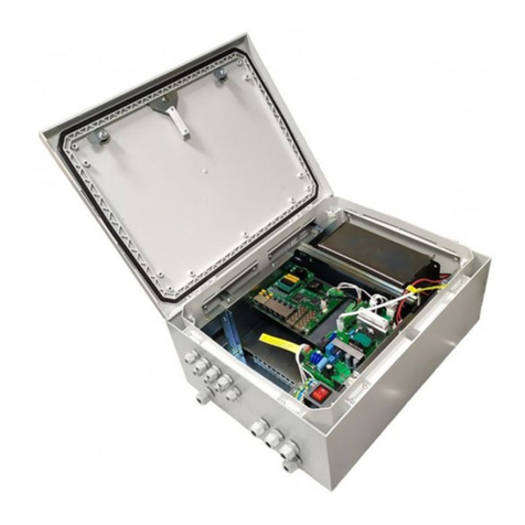
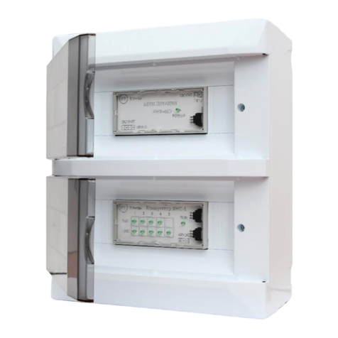
TFortis PSW-1-45-WiFi User manual

1
Operation Manual
PSW-1-45-WiFi
Multifunctional Unmanaged Switch
for IP Video Surveillance Systems
Version 2
Power supply elements are under high voltage. It is
strictly forbidden to touch conducting elements of
the power supply unit under voltage.
!
Before connecting a laptop to port 5 of the switch,
put Passive PoE jumpers into the OFF position.
!
For effective lightning protection the following is
required:
•proper grounding made according to the
Electrical Code;
•a shielded twisted pair with shielded RJ45
connectors;
•minimum length of the twisted pair and power
supply cables.

2
Contents
Contents.....................................................................................................2
1. Designation ............................................................................................3
2. Description .............................................................................................5
2.1. Appearance......................................................................................5
2.2. Components layout..........................................................................6
2.3. PoE power supply............................................................................7
2.4. Lightning protection..........................................................................7
2.5. Restarting cameras in case of hanging ............................................8
3. Technical parameters.............................................................................9
4. Operating conditions...............................................................................9
5. Installation............................................................................................10
5.1. Unit mounting.................................................................................10
5.1.1. Wall mounting..........................................................................10
5.1.2. Mounting on the pole...............................................................11
5.1.3. Installation into TFortis CrossBox cabinet................................11
5.2. Power supply connection ...............................................................12
5.3. Connecting the cameras and access point.....................................12
6. Manufacturer's warranty .......................................................................13

3
1. Designation
PSW-1-45-WiFi switch is an unmanaged outdoor Fast Ethernet switch used
for the construction of IP video surveillance networks.
220 VAC
10/100Base-Tx
10/100Base-TX + PoE
Figure 1-1. PSW-1-45-WiFi switch, connection over twisted pair
220 VAC
10/100Base-Tx + PoE 24V
10/100Base-TX + PoE
Figure 1-2. PSW-1-45-WiFi switch, connection over Wi-Fi

4
Weatherproof design
The switch body is made of technopolymer resistant to severe operating
conditions. Dust and moisture protection casing IP66.
Operation in extreme temperatures
The switch comprises industrial hardware components with a wide range of
operating temperatures. Application of industrial SFP modules will ensure
normal operation in the temperature range from –55°C to 65°* (-67 to
149F)*.
*The maximum temperature depends on the load (see diagram in section
4. Operating conditions)
PoE support (IEEE802.3af)
The switch may supply PoE to any camera compliant with IEEE802.3af
standard. Power is supplied through free pairs (either [1,2 and 3,6] or [4,5
and 7,8]). The mode of power supply is defined by jumpers.
Passive PoE support (24V)
Port №5 supports Passive PoE 24V, which allows to connect wireless
access points such as Ubiquiti or MikroTik.
Connection to 220V
A built-in power supply unit ensures direct connection of the switch to 220V
power supply eliminating the need for an additional power supply unit.
Lightning protection
A built-in lightning protection for Ethernet ports and 220V power supply
protects the switch and connected cameras from surges caused by
electrostatic discharges.
Circuit breaker compartment
The switch has a circuit breaker compartment, which eliminates the need
for additional cabinets or boxes.
Automatic cameras restart in case of hanging
The switch controls operation of the cameras. In case of hanging, the
switch will reboot the camera automatically over PoE. It allows to create
unattended IP video surveillance networks.
5
2. Description
2.1. Appearance
Figure 2.1-1. PSW-1-45-WiFi switch, exterior view
Figure 2.1-2. PSW-1-45-WiFi switch, interior view (circuit breakers are not
included)

6
2.2. Components layout
Figure 2.2. Layout of components inside PSW-1-45-WiFi switch
During normal processor operation, CPU indicator should blink in 2-second
intervals (1 second ON, 1 second OFF).

7
2.3. PoE power supply
PSW-1-45-WiFi switch supports the following types of power supply:
•IEEE802.3af power supply for ports 1 to 4,
•Passive PoE 24V (pairs 4,5 and 7,8) for port 5.
Passive PoE on port 5 is activated by the jumper. Before connecting a
laptop to port 5, put Passive PoE jumpers into the OFF position.
2.4. Lightning protection
PSW-1-45-WiFi switch has built-in lightning protection modules that
protect Ethernet ports and 220V power circuits from common-mode and
differential electromagnetic interferences.
The switch is resistant to powerful microsecond pulse interferences
according to GOST R 51317.4.5 standard with the degree of severity
according to Table 2.4-1, performance criteria B.
The switch is resistant to AC transients in the power supply circuit
according to GOST R 51317.4.11 standard, Table 2.4-2, performance
criteria B.
Table 2.4-1.
Port
Degree of severity according to
Table 1, GOST R 51317.4.5
Voltage surge value, kV+ 10%
Wire-to-wire power supply
circuits
3
2
Wire-to-ground power supply
circuits
4
4
Wire-to-ground balanced
communication circuits
3
2

8
Table 2.4-2.
Type of impact
Degree of test severity
Test voltage,
% Un, + 5 %
Voltage transients
amplitude, % Un
Voltage transients
duration, intervals (ms)
Voltage dips
1
70
30
10 (200)
Voltage
interruptions
1
0 to 20
100
1 (20)
Voltage surges
2
120
20
25 (500)
Note: Un is the nominal power supply voltage.
("Performance criteria B" means temporary disruption of performance or
functioning with further recovery without operator's intervention)
Continued operation with changes in the supply voltage from ~187 to
~246V.
2.5. Restarting cameras in case of hanging
PSW-1-45-WiFi switch continuously monitors traffic intensity of the camera.
If network activity is lost, the switch will reboot the camera by disconnecting
PoE power supply. This function is activated by a jumper for each particular
port.

9
3. Technical parameters
Ports 1 to 4
•10/100Base-Tx –4 pcs;
•IEEE802.3af support –15.4 W per port;
•Auto-MDIX support;
•IEEE 802.3x flow control support;
•PoE and data transfer distance –up to 100 m.
Port 5
•10/100Base-Tx –1 pc;
•Passive PoE 24V support (pairs 4,5 and 7,8) –24V, 0.5A;
•pairs 4,5 "+", pairs 7,8 "–"
•Auto-MDIX support;
•IEEE 802.3x flow control support;
•PoE and data transfer distance –up to 100 m.
Power supply
•PSU voltage ~ 220V (187 to 246V);
•PoE power budget –50W maximum;
•maximum power consumption –60W.
Design
•dimensions –240x160x90 mm;
•maximum weight –2 kg;
•IP66 casing;
•cable glands
–4-8 mm cable –5 glands
–6-12 mm cable –2 glands
Reliability
•meantime between failures –at least 50 000 hours (5-7 years).
4. Operating conditions
PSW-1-45-WiFi switch is designed for 24/7 outdoor operation at the
ambient temperatures from –55 to +65C* (-67 to 149 F)*.

10
*The maximum temperature depends on the load (see diagram)
Note 4.1.
PSW-1-45-WiFi switch maintains declared parameters at storage
temperatures from -55 C to +50 C (-67 to 122 F).
5. Installation
5.1. Unit mounting
5.1.1. Wall mounting
The housing has four attachment points at the edges. Marking of the
attachment points is shown in Figure 5.1.1.
226
146
4
PSW-1-45-WiFi
Figure 5.1.1. Attachment points marking
WARNING! Drilling of the housing will lead to loss of the switch integrity
and, as a result, loss of product warranty.

11
5.1.2. Mounting on the pole
To install PSW-1-45-WiFi switch on the pole, use TFortis mounting panel.
Figure 5.1.2. Mounting the switch on the pole
5.1.3. Installation into TFortis CrossBox cabinet
TFortis PSW-1-45-WiFi switches have a hermetically sealed housing of
technopolymer providing IP66 protection rating. This ensures safe outdoor
installation without the need for an additional metal enclosure. To provide
extra protection from vandals, a TFortis CrossBox cabinet may be used.
Figure 5.1.3. TFortis CrossBox-1 cabinet with a PSW-1-45-WiFi switch

12
5.2. Power supply connection
PSW-1-45-WiFi switch is connected to 220V AC power supply. Power
supply cable is pulled into the unit trough a cable gland and is connected to
the power supply terminal block either directly or via a circuit breaker
assembly.
WARNING! Grounding of the switch is required. Grounding resistance
should not exceed 4 Ohm.
WARNING! Energized high-voltage conductors should never be in contact
with circuit boards. The resulting failure will lead to loss of product
warranty.
WARNING!
The switch contains static power supply units and, therefore, is a reactive
load. Inrush currents that occur during charging of the input capacitors will
exceed nominal current values. To prevent false tripping of the circuit
breakers, it is recommended to choose models with characteristic C and at
least 4A current.
5.3. Connecting the cameras and access point
It is recommended to use a 4-pair shielded cable, at least category 5.
Ethernet cable is pulled into the switch through a cable gland, clamped and
connected to RJ45 ports. For more convenient clamping, a cable gland
may be removed and then re-installed. Unused cable glands should be
sealed off.
Figure 5.3.1 Cable termination.

13
6. Manufacturer's warranty
The warranty period for the switch is 36 months from the date of sale. Only
a complete switch is accepted for servicing and repair.
Warranty shall not apply in the following cases:
•if the warranty period has expired;
•if manufacturer's marking with the serial number on the housing is
missing or if the serial number has been changed, removed or is
illegible;
•if there are internal or external mechanical damages (chipping,
cracking, deformation, damaged power supply wires, cracking or
splitting of the terminals), signs of treatment with aggressive
chemicals or fluids, severe contamination, insects presence or signs
of insects presence;
•in case of improper connection and operation of the switch or if power
supply parameters do not meet the requirements specified in this
operating manual;
•if the switch was damaged as a result of force majeure, due to the
actions of third parties or other reasons beyond manufacturer's
control.
Table of contents
Other TFortis Switch manuals

TFortis
TFortis PSW-2G+ Installation manual

TFortis
TFortis SWD-1 User manual

TFortis
TFortis PSW-2G6F+UPS-Box User manual

TFortis
TFortis PSW-2G2F+UPS User manual

TFortis
TFortis PSW-2G8F+Hot User manual

TFortis
TFortis PSW-11 User manual

TFortis
TFortis PSW-2G4F-Ex Instruction sheet

TFortis
TFortis PSW-2G+Hot User manual

TFortis
TFortis PSW-2G4F-Box User manual

TFortis
TFortis PSW-1G4F-Box User manual
Popular Switch manuals by other brands

LeisureTech
LeisureTech Forte A-BUS How to install

Hama
Hama Quad Switch LNB operating instructions

Frequency Central
Frequency Central Where Build documentation

Moxa Technologies
Moxa Technologies EtherDevice user manual

CYP
CYP EL-31TT-4K22 Operation manual

Cisco
Cisco Cisco Small Business Unmanaged Switch SR2016 datasheet