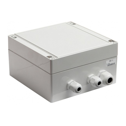
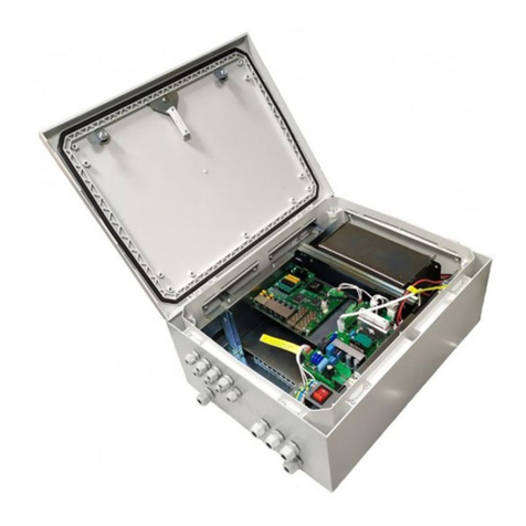
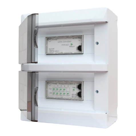
TFortis PSW-2G+Hot User manual

Multifunction Gigabit Managed Switch
with PoE+ support (IEEE802.3at) up to 60 W per port
for connecting four IP video cameras,
designed to be used in hot climate
PSW-2G+Hot
Operating Manual
Version 1

2
Warning!
Power supply elements are under high voltage. It is
strictly forbidden to touch conducting elements of the
power supply unit under voltage.
!
SFP port operates only at 1000 Mbps. Fast Ethernet SFP
modules will not operate.
!
To ensure proper operation of lightning protection:
•provide proper grounding according to the
Electrical Code;
•use a shielded twisted pair with shielded RJ45
connectors;
•use minimum length of the twisted pair and power
supply cables

3
Contents
1 Purpose .............................................................................................................................4
2 Features............................................................................................................................5
3 Description ......................................................................................................................7
3.1 Enclosure ......................................................................................................................7
3.2 Optical distribution frame...............................................................................................9
3.3 Power supply unit..........................................................................................................9
3.4 Switch board................................................................................................................10
3.4.1 CPU button...........................................................................................................11
3.4.2 DEFAULT button..................................................................................................11
3.4.3 CPU indicator.......................................................................................................11
3.4.4 DEFAULT indicator ..............................................................................................11
3.4.5 PoE indicators......................................................................................................12
3.4.6 LINK indicators.....................................................................................................12
3.4.7 Power indicators...................................................................................................12
3.5 Tamper sensor............................................................................................................12
3.6 Lightning protection modules.......................................................................................13
3.7 Automatic circuit breaker.............................................................................................14
3.8 Additional functions .....................................................................................................15
3.8.1 Restarting cameras in case of hanging................................................................15
3.8.2 Cable tester..........................................................................................................16
3.8.3 Remote camera polling ........................................................................................16
4 Technical specifications...........................................................................................16
5 Operating conditions ..................................................................................................17
6 Preliminary setting......................................................................................................17
6.1 Resetting the switch to factory settings .......................................................................17
6.2 IP address setting........................................................................................................17
6.3 User name and password setting................................................................................18
6.4 Activation of redundancy protocols..............................................................................18
7 Installation of the switch..........................................................................................19
7.1 Installation of the cabinet on the wall...........................................................................19
7.2 Installation of the cabinet on lamp posts......................................................................20
7.3 Optical connections.....................................................................................................20
7.4 Power supply connection.............................................................................................21
7.5 Camera connection .....................................................................................................21
8 Manufacturer's warranty...........................................................................................22
9 Technical support........................................................................................................23

4
1 Purpose
PSW-2G+Hot device is a multifunction gigabit outdoor managed switch
designed for the construction of IP video surveillance networks.
PSW-2G+Hot connection scheme

5
2 Features
The switch is built based on industrial hardware with a wide range of operating
temperatures. All heat-generating components of the switch are provided with
heat removal to the switch enclosure. The enclosure acts as a radiator. The
enclosure has a shield to reflect sunlight. Industrial SFP modules can be
operated normally in the temperature range from –40°C to +75°C.
The aluminum enclosure has dust and moisture protection rating IP67. All
cables are pulled into the switch enclosure through a cable gland.
The key element of the switch is a high-performance chip from Marvell, which is
able to process large amounts of traffic coming from the IP video cameras.
The switch can supply any video camera compliant with IEEE802.3af or
IEEE802.3at standards (up to 60W).
A built-in power supply unit ensures direct connection to ~230VAC power
supply, eliminating the need for an additional power supply unit.
A built-in lightning protection for Ethernet ports and ~230VAC power supply
protects the switch and connected cameras from pulse interferences caused by
lightning discharges.
Operation in extreme temperatures
All-weather design
High performance gigabit switch
PoE+ support
Connection to 230VAC
Lightning protection

6
The switch controls operation of the camera. In case of hanging, the switch will
restart the camera automatically over PoE. It allows to build unattended IP
video surveillance systems.
Two gigabit ports allow to connect switches in a chain. Support of STP/RSTP
protocols allows to create ring topologies, which significantly improves fault
tolerance of the system.
The switch enclosure has a tamper sensor. Opening of the cabinet door will
generate an alarm message to be sent to the server via SNMP or Syslog
protocols.
The optical distribution frame allows for optical cable splicing inside the switch
and connecting it to SFP modules.
The automatic circuit breaker allows to de-energize the switch during
configuring and debugging.
Cameras restart automatically in case of hanging
Operation in a ring or a chain configuration
Unauthorized access control
Integrated optical distribution frame
Automatic circuit breaker

7
3 Description
3.1 Enclosure
External view View with the shield removed
Figure 3.1.1 PSW-2G+Hot switch
Figure 3.1.2 PSW-2G+Hot interior

8
Features of the switch enclosure
•The aluminum enclosure is compact and has dust and moisture protection
rating IP67.
•Vents provide air circulation between the shield and the enclosure for
additional cooling of the switch.
•The shield is attached to the enclosure at several points to eliminate heat
passage from the external casing into the switch. All heat-generating
components of the switch are connected to the enclosure. This allows to
dissipate heat from electronic components out of the switch.
A combination of the above technical solutions allows the switch to operate in
hot climate.
Figure 3.1.3 Switch operation in hot climate

9
3.2 Optical distribution frame
IMPORTANT!
The scope of
supply
does NOT
include
nylon ties,
shrinkable
plastic sleeves,
pigtails and
adapters.
Figure 3.2.1 Optical distribution frame
3.3 Power supply unit
The power supply unit is located under the switch board. Access to the power
supply unit is limited. The power supply unit has an aluminum radiator that is
pressed against the back panel of the switch to remove the heat to the switch
enclosure.

10
Figure 3.3 Power supply unit
3.4 Switch board
The switch board is mounted on an aluminum plate that removes the heat from
hot electronic components to the switch enclosure.
Figure 3.4.1 Switch board

11
Figure 3.4.2 Layout of components on the switch board
3.4.1 CPU button
To restart the switch, short press the CPU button.
3.4.2 DEFAULT button
To restore factory settings, press the DEFAULT button and hold it down for
about 15 seconds. The DEFAULT indicator should set ON at this point.
3.4.3 CPU indicator
During normal processor operation, the CPU indicator should blink in 2-second
intervals (1 second ON, 1 second OFF)
3.4.4 DEFAULT indicator
DEFAULT indicator is ON when the device has the factory settings (IP
192.168.0.1).

12
3.4.5 PoE indicators
The PoE A indicator is ON when power is supplied over data (pairs 1, 2 and 3,
6). The PoE B indicator is ON when power is supplied via free pairs (pairs 4, 5
and 7, 8).
3.4.6 LINK indicators
A blinking LINK indicator shows that data are transmitted via the corresponding
port.
3.4.7 Power indicators
Power indicators show the presence of power supply on the switch boards.
3.5 Tamper sensor
The optical tamper sensor is located inside the switch (Figure 3.5.1). The optical
tamper sensor is more reliable than sealed and limit switches, because it does
not get stuck and does not chatter. Its operating principle is simple. When the
power supply unit is closed, a curtain (Figure 3.5.2) installed on its cover
discontinues the optical flow. When the power supply unit is opened, the curtain
moves out of the sensor and triggers it.
Figure 3.5.1 Tamper sensor on the switch board

13
Figure 3.5.2 Tamper sensor curtain on the power supply unit cover
IMPORTANT! Make sure you place the power supply unit cover correctly when
closing it. The shutter shall fall between the tamper sensor ends.
3.6 Lightning protection modules
PSW-2G+Hot switch has built-in lightning protection modules that protect
Ethernet ports and 230 VAC power circuits from common-mode and differential
electromagnetic interferences.
The switches are resistant to powerful microsecond pulse interferences
according to GOST R 51317.4.5 as per Table 3.7.1 with performance criteria B
(temporary disruption of performance or functioning with further recovery
without operator's intervention).
Table 3.7.1
Port
Pulse
2 kV

14
4 kV
2 kV
IMPORTANT! Grounding of the switch is mandatory for lightning protection.
3.7 Automatic circuit breaker
The switch is provided with an automatic circuit breaker for ease of
maintenance.
Figure 3.7 Automatic circuit breaker

15
3.8 Additional functions
3.8.1 Restarting cameras in case of hanging
PSW-2G+Hot continuously monitors connection of the camera to the switch.
There are three ways to detect camera hanging:
•No connection to the camera (Link)
•No response to service requests (Ping)
•Reduction of port speed below the established limit (Speed)
The switch continuously (once a minute) monitors the Link signal from the IP
camera. If the switch fails to detect the Link signal, then a one-minute timer is
started, and after that the connection is checked again. If the Link signal does
not appear, the switch removes power for 10 seconds and supplies it again,
restarting the camera. In other words, if the switch fails to see the Link signal
from the camera twice in succession at an interval of 1 minute, it restarts the
camera. The Auto Restart option is available via the Web interface in the
Special Function section (see the Configuration Manual).
The switch constantly (1 time per minute) polls the IP camera. If the switch does
not receive a response, then a one-minute timer is started, during this time the
poll is repeated every 10 seconds. If the camera has not responded within a
minute, the switch removes power from the camera for 10 seconds and supplies
it again, restarting the camera. If the camera has responded at least once, the
switch decides that the camera is functional and starts the poll cycle again,
polling the camera 1 time per minute. The Auto Restart option is available via
the web interface in the Special Function section. To use this function, it is
necessary to enter the IP address of the camera. Make sure your camera
responds to PING (see the Configuration Manual).
The switch continuously monitors the speed on the port the camera is
connected to. If the flow rate goes below the established limit and fails to
Video camera restart using Link signal
Camera restart due to no response to Ping request
Camera restart in case of port speed reduction

16
restore, the switch decides that the camera is hanging and restarts it. The user
may specify the limit values (see the Configuration Manual).
3.8.2 Cable tester
The switch can function as a virtual cable tester (VCT), which allows to
determine the breakage of the twisted pair, short-circuiting of the twisted pair
wires, cable disconnection from the camera, distance from the switch to the
fault. The cable tester is used to test pairs that transmit data (1, 2 and 3, 6).
Note that the accuracy of the cable tester is ± 2 meters.
By default, VCT operates on an average algorithm and does not take into
account the specific features of a particular cable, which can affect the accuracy
of the measurement. To improve the accuracy of the cable tester, it is
recommended to calibrate it. Note that calibration is not recommended for
cables shorter than 10 meters.
3.8.3 Remote camera polling
Using the switch, it is possible to ping any device on the network through the
web interface, which is convenient when solving network problems.
4 Technical specifications
Gigabit Ethernet ports
•1000Base-X with SFP connector;
•Number of ports –2;
Fast Ethernet ports
•10/100Base-Tx with RJ-45 connector;
•number of ports –4;
•Auto-MDIX support for 10/100Base-Tx port;
•IEEE 802.3x flow control support;
•PoE/PoE+ (IEEE802.3af/at) support by option A and B simultaneously –
up to 60W;
•total power should not exceed 160 W;
•transmission distance –up to 100 m.
Power supply
•voltage –230 VAC (187 to 253 V);

17
•Maximum power consumption –200 W.
Design
•dimensions –459х247х175 mm
•maximum weight –11 kg
•environmental protection rating IP67
•cable glands
–4-8 mm cable –8 pcs.
–6-12 mm cable –3 pcs.
Reliability
•meantime between failures at least 75 000 hours (8.6 years).
5 Operating conditions
The switch is designed for 24/7 outdoor operation at the ambient temperature
from –40°C to +75C with industrial SFP modules.
The switch remains fully functional after exposure to ambient temperatures from
–40C to +50C.
6 Preliminary setting
6.1 Resetting the switch to factory settings
Before start, set the switch to default settings. To do this, press and hold the
DEFAULT button until the DEFAULT indicator is ON. The default IP address of
the switch is 192.168.0.1.
6.2 IP address setting
All software functions of the switch can be managed, configured and monitored
using the built-in WEB interface and Telnet. Below is the description of WEB-
based configuration. Configuration via Telnet (see the Configuration Manual).
The switch can be managed from remote stations at any point of the network
via a standard web browser (for example, Microsoft Internet Explorer). The
browser is a universal access tool and can directly access the switch using the
HTTP protocol.

18
Connect any switch port to an Ethernet network. Note that if the device is
configured over a network, the IP address of the management workstation
should belong to the same IP network. For example, if the default IP address of
the switch is 192.168.0.1, then the IP address of the workstation should be
192.168.0.x (where x is a number from 2 to 254); the default subnet mask is
255.255.255.0.
Open the web browser and enter the IP address http://192.168.0.1.
Figure 6.2 Entering the IP address of the switch
6.3 User name and password setting
Until the "user name" and "password" are set, you will log in without entering
this data. After the password is set, you will need to authenticate when you log
in.
Figure 6.3 Entering user name and password.
IMPORTANT! Note that the user name and password are case sensitive.
6.4 Activation of redundancy protocols
If you connect the switches into a ring, then you need to enable the RSTP
protocol. Otherwise, if there are alternative paths, your network will not be
functional. By default, RSTP is turned off.

19
7 Installation of the switch
7.1 Installation of the cabinet on the wall
The cabinet has four attachment points. Marking of the attachment points is
shown in Figure 7.1.
Figure 7.1 Marking of attachment points
IMPORTANT! Drilling of the enclosure will lead to loss of the switch integrity
and result in the loss of product warranty.

20
7.2 Installation of the cabinet on lamp posts
To install the cabinet on the lamp post, use TFortis Attachment Set (pole mount
kit KKC-Hot), see the KKC-Hot Operating Manual.
Figure 7.2 After installing the cabinet attach the top shield.
IMPORTANT! KKC-Hot is not included in the scope of supply
7.3 Optical connections
The switch has an optical distribution frame. For ease of operation, the optical
distribution frame can be removed from the cabinet. The optical cable is pulled
into PG13.5 cable glands. The optical cable is attached to the metal base of the
distribution frame with nylon ties. Optical fibers are laid in a splice cassette for
12 shrinkable plastic sleeves. Welded pigtails are connected to SC adapters
located on the adapter panel. Then the adapters are connected to SFP modules
with the use of optical patch cords. It is allowed to connect the pigtails directly to
SFP without any unnecessary connections.
Table of contents
Other TFortis Switch manuals

TFortis
TFortis PSW-11 User manual

TFortis
TFortis PSW-2G+ Installation manual

TFortis
TFortis PSW-2G4F-Ex Instruction sheet

TFortis
TFortis PSW-2G4F-Box User manual

TFortis
TFortis PSW-1G4F-Box User manual

TFortis
TFortis PSW-2G8F+Hot User manual

TFortis
TFortis SWD-1 User manual

TFortis
TFortis PSW-2G6F+UPS-Box User manual

TFortis
TFortis PSW-2G2F+UPS User manual

TFortis
TFortis PSW-1-45-WiFi User manual