TGB CH1 User manual

CH1/CR1 50 ㏄
OWNER-MANUAl
MAINTENANCE HANDBOOK
TAIWAN GOLDEN BEE CO.,LTD.

TGB CONTENTS
CONTENTS
GENERAL INFORMATION/TROUBLE DIAGNOSIS...................................1
MAINTENANCE INFORMATION .................................................................2
LUBRICATION SYSTEM..............................................................................3
FUEL SYSTEM.............................................................................................4
ENGINE REMOVAL......................................................................................5
CYLINDER HEAD/VALVE............................................................................6
CYLINDER/PISTON......................................................................................7
"V" TYPE BELT DRIVING SYSTEM/KICK STARTER ARM .......................8
FINAL DRIVING MECHANISM.....................................................................9
A.C. GENERATOR/STARTING CLUTCH....................................................10
CRANKCASE/CRANKSHAFT .....................................................................11
SPECIAL TOOL............................................................................................12
TGB 1. GENERAL INFORMATION/TROUBLE DIAGNOSIS
1-1
SPECIFICATIONS..............................1-1
TORQUE VALUES (ENGINE) ..........1-2 TROUBLES DIAGNOSIS...................1-4
SPECIFICATIONS
MAKER TGB MODEL CH1/CR1
Overall Length 1780mm Primary
Reduction BELT
Overall Width 695mm Secondary
Reduction GEAR
Overall Height 1075/1170mm Clutch One-way
DIMENSION
Wheel Base 1285mm
Deceleration
equipment
Transmission C.V.T.
Exhaust Pipe Position
and Direction Right side, and
Backward
Lubrication System Separated-lubrication
WEIGHT
Curb Weight
92/102kg Solid
Particulate 15 % ↓
Type 4-STROKE ENGINE CO 2.5±0.5 % ↓
Installation and
arrangement Vertical, below center,
incline 80°
Exhaust
Concentration
HC Below 800 PPM
Fuel Used Unleaded (92/95) Head 12V 35/35W
Cycle/Cooling 4-stroke/forced air
cooled Rear 5W
Bore φ39.0 mm Brake 21W
Stroke 41.5 mm
LAMPS
Turn 10W×4
Cylinder
Number/Arran
gement Single Cylinder/
horizontal
Inflation
Pressure
(Ffront/Rear) 1.75㎏f/㎝2 / 2.10㎏f/㎝2
Displacement 49.5 cc
TIRE
Type F:120/70-12 R:120/70-12
Compression
Ratio 11.8±0.1 Lubricate Oil SAE10W-30(0.85L)
Max. HP 2.35KW/ 7500 rpm Gear Oil SAE 85W-140(0.12L)
Max. Torque 2.96N.m /6500 rpm Battery 12V/5AH
Ignition C.D.I. Brake system F:Disc R:Drum
ENGINE
Starting System Electrical & foot type

1. GENERAL INFORMATION/TROUBLE DIAGNOSIS TGB
1-2
TORQUE VALUES (ENGINE)
ITEM Q'TY
THREAD DIA
(mm) TORQUE
VALUE(Kg-m) REMARKS
Cylinder head cover bolts 4 6 0.8~1.2
Cylinder head nuts 4 7 1.0~1.4 Apply oil thread
Cylinder/cylinder head
two-ends bolts 4 7 0.7~1.1 Tighten to crankcase
Cylinder head left bolts 2 6 0.8~1.2
Valve adjustment fixing nuts 2 5 0.7~1.1 Apply oil to thread
Spark plug 1 10 1.0~1.4
Carburetor heat protector
connectin
g
nuts 2 6 0.7~1.1
Engine oil draining plug 1 12 3.5~4.5
Engine oil strainer cap 1 30 1.3~1.7
Gear oil draining plug 1 8 1.0~1.5
Gear oil filling bolt 1 8 1.0~1.5
Oil pump screws 3 3 0.1~0.3
Engine left side cover bolts 9 6 0.8~1.2 Rubber washer
attached
Camshaft chain tensioner
bolt 1 8 0.45~0.6 Hex socket bolt
Camshaft chain adjuster
bolts 2 6 0.8~1.2
Clutch driving plate nut 1 28 5.0~6.0
Clutch outer bracket nut 1 12 3.5~4.5
Driving disk nut 1 10 3.5~4.5
Flywheel nut 1 10 3.5~4.5
Crankcase bolts 9 6 0.8~1.2
Gear box cap bolts 7 8 2.6~3.0
Exhaust pipe bolts 2 6 0.7~1.1

TGB 1. GENERAL INFORMATION/TROUBLE DIAGNOSIS
1-3
The torque values listed in above table are for more important tighten torque values. Please see
standard values for not listed in the table.
Standard Torque Values for Reference
TYPE TIGHTEN TORQUE TYPE TIGHTEN TORQUE
5mm bolt、nut 0.45~0.60kgf-m 3mm screw 0.05~0.08kgf-m
6mm bolt、nut 0.80~1.20kgf-m 4mm screw 0.10~0.15kgf-m
8mm bolt、nut 1.80~2.50kgf-m 5mm screw 0.35~0.50kgf-m
10mm bolt、nut 3.00~4.00kgf-m 6mm screw、SH nut 0.70~1.10kgf-m
12mm bolt、nut 5.00~6.00kgf-m 6mm bolt、nut 1.00~1.40kgf-m
8mm bolt、nut 2.40~3.00kgf-m
10mm bolt、nut 3.50~4.50kgf-m

1. GENERAL INFORMATION/TROUBLE DIAGNOSIS TGB
1-4
TROUBLES DIAGNOSIS
A. Engine hard to start or can not be started
Check and adjustment Fault condition Probable causes
Loosen carburetor drain
bolt to check if there is
gasoline inside the
carburetor
Fuel supplied tom
carburetor sufficient No fuel is supplied to
carburetor
Remove spark plug, install
it into spark plug cap, and
perform a spark test
against engine ground.
perform cylinder
compression pressure test.
Check if sparks Weak sparks, no spark
at all
Low compression
pressure or no pressure
Re-start by following the
starting procedures
No ignition There are some signs of
ignition, nut engine can
not be started
Remove the spark plug
again and check it.
Remove carburetor after 30 minutes
and connect a hose onto fuel rich
circuit. Then blow the hose with air
Dry spark plug Wet spark plug
Blowing in normal Blowing clogged
1. No fuel in fuel tank
2. Check if the pipes, fuel tank to
carburetor and intake vacuum,
are clogged.
3. Float valve clogged
4. Lines in fuel tank evaporation
system clogged
5. Malfunction of fuel pump
6. Loosen or damaged fuel pump
vacuum hose
7. Fuel filter clogged
1. Malfunction of spark plug
2. Spark plug foul
3. Malfunction of CDI set
4. Malfunction of AC generator
5. Ignition coil is in open or short
circuit
6. Ignition coil leads open or short
circuit
7. Malfunction of main switch
1. Piston ring seized
2. Malfunction of cylinder valves
3. Worn cylinder and piston ring
4. Cylinder gasket leak
5. Sand hole in compression parts
1. Malfunction of throttle valve
operation
2. Air sucked into intake manifold
3. Incorrect ignition timing
1. Fuel level in carburetor too high
2. Malfunction of throttle valve
operation
3. Throttle valve opening too wide
1. Malfunction of automatic by-
starter
cylinder compression
pressure normal

TGB 1. GENERAL INFORMATION/TROUBLE DIAGNOSIS
1-5
B. Engine run sluggish (Speed does not pick up, lack of power)
Check and adjustment Fault condition Probable causes
Try gradual acceleration
and check engine speed
Engine speed can be
increased. Engine speed can not be
increased.
Check ignition timing
(Using ignition lamp)
Check cylinder compression
pressure (using compression
pressure gauge)
Ignition timing correct Incorrect ignition timing
Compression pressure correct No compression
Check if carburetor jet is
clogged
No clogged Clogged
Remove spark plug
Check if engine over heat
No foul or discoloration Fouled and discoloration
No knock Knock
1. Air cleaner clogged
2. Poor fuel supply
3. Lines in fuel tank evaporation
system clogged
4. Exhaust pipe clogged
5. Fuel level too low in carburetor
6. Fuel nozzle clogged in
carburetor
1. Malfunction of CDI
2. Malfunction of AC alternator
1. Cylinder & piston ring worn out
2. Cylinder gasket leaked
3. Sand hole in compression parts
4. Valve deterioration
5. Seized piston ring
1. Remove foreign
1. Remove dirt
2. Incorrect spark plug heat range
1. Piston and cylinder worn out
2. Lean mixture
3. Poor fuel quality
4. Too much carbon deposited in
combustion chamber
5. Ignition timing too advanced
6. Poor circuit on the cooling
s
y
stem
Normal Engine overheat
Continually drive in
acceleration or high speed
1. Too much carbon deposited in
combustion chamber
2. Lean mixture
3. Poor fuel quality
4. Ignition timing too advanced

1. GENERAL INFORMATION/TROUBLE DIAGNOSIS TGB
1-6
C. Engine runs sluggish (especially in low speed and idling)
D. Engine runs sluggish (High speed)
Check ignition timing
(using ignition lamp)
Good spark Poor
No air sucked Air sucked
Good Poor
Abnormal
Air sucked through
carburetor gasket
Adjust the air screw of
carburetor
Remove spark plug, install
spark plug into spark plug
cap and perform spark test
against engine ground
Normal
Check and adjustment Fault condition Probable causes
Check for fuel supplying
system in automatic fuel cup
Check if carburetor clogged
1. Incorrect ignition timing (malfunction
of CDI or AC alternator)
1. Rich mixture (loosen the screw)
2. Lean mixture (tighten the screw)
1. Poor heat insulation gasket
2. Carburetor lock loose
3. Poor intake gasket
4. Poor carburetor O-ring
5. Vacuum hose crack
1. Spark plug fouled
2. Malfunction of CDI
3. Malfunction of AC generator
4. Malfunction of ignition coil
5. Open or short circuit in spark plug
leads
6. Malfunction of main switch
1. Insufficient fuel in fuel tank
2. Fuel filter clogged
3. Restricted fuel tank vent
Good Poor
Check and adjustment Fault condition Probable causes
Check ignition timing
1. Malfunction of CDI
2. Malfunction of AC alternator
Normal Abnormal
No clogged Clogged 1. Cleaning
TGB 1. GENERAL INFORMATION/TROUBLE DIAGNOSIS
1-7
E. CLUTCH, DRIVING AND DRIVING PULLEY
1. Clutch ling spring broken
2. Clutch outer stick with clutch balance weights
3. Connection parts in clutch and shaft worn out
or burned
Engine can be started but
motorcycle can not be moved.
FAULT CONDITIONS PROBABLE CAUSES
1. Driving belt worn out or deformation
2. Driving disk damaged
3. Driving pulley spring broken
4. Clutch ling broken
5. Driving slide-shaft gear groove broken
6. Transmission gear damaged
Engine running and misfire as
motorcycle initial forward moving
or jumping suddenly (rear wheel
rotating as engine in running)
Poor initial driving ( Poor
climbin
g
p
erformance
)
1. Driving belt worn out or deformation
2. Balance weight roller worn out
3. Driving sliding gear shaft worn out
4. Driving disk spring deformation
5. Driving sliding gear shaft worn out
6. Greased in driving belt and sliding gear.
TGB 2. MAINTENANCE INFORMATION
2-1
PRECAUTIONS IN OPERATION .......2-1
PERIODICAL MAINTENANCE SCHEDULE........2-2
LUBRICATION SYSTEM....................2-3
VALVE CLEARANCE ADJUSTMENT 2-4
CARBURETOR IDLING SPEED ADJUSTMENT 2-5
IGNITION SYSTEM/SPARK PLUG .. 2-6
CYLINDER COMPRESSION PRESSURE .2-7
DRIVING SYSTEM............................. 2-7
PRECAUTIONS IN OPERATION
Specification
capacity 850 c.c.
Engine Oil change 750 c.c.
capacity 120 c.c.
Transmission Gear oil change 110 c.c.
Clearance of throttle valve 2~6 mm
Spark plug TORCH A7RC Gap: 0.6~0.7 mm
“F” Mark in idling speed Before TDC 13º / 2200 rpm
Full timing advanced Before TDC 26º / 8000 rpm
Idling speed 2200±100 rpm
Cylinder compression pressure 12±2 kg/cm²
Valve clearance: IN/EX 0.06±0.02 mm

2. MAINTENANCE INFORMATION TGB
2-2
PERIODICAL MAINTENANCE SCHEDULE
Maintenance
Code Item Initial 500KM 6 Month
Every3000KM
12 month
Every6000KM
18 month
Every9000KM
24 month
Every12000KM
01 ☆Engine oil R R
ENGINE OIL SHALL BE CHANGED PER 1000KM
02 ☆Filter, Engine oil C C C C C
03 ☆Air Cleaner C R C R
04 ☆Second-Air Control Assy C R C R
05 ☆Spark plug C R C R
06 ☆Carburetor I I,A I,A I,A I,A
07 ☆Idle speed A A A A A
08 ☆Throttle Cable I I I I I
09 ☆Brake System I,A I,A I,A I,A I,A
10 ☆Wheel I I I I
11 ☆Nut,Bolt,Fastener I I I I I
12 ☆Battery I I I I
13 ☆C.V.T Belt I R I R
14 ☆Oil,Reducing Gear Box R R R
15 ☆Fuel Filter I R I R
16 ☆Speedometer Gear Box L L L
17 ☆Front Fork I I I
18 ☆Absorber Shock,Rear I,A I,A I,A
Code: I ~ InspecT or replace if necessary A ~ adjustment R ~ Replacement C ~ Cleaning (replaced if necessary)
L ~ Lubrication
Have your motorcycle checked, adjusted, and recorded maintenance data periodically by your TGB Authorized Dealer to
maintain the motorcycle at the optimum condition
The above maintenance schedule is established by taking the monthly 1000 kilometers as a reference which ever comes
first.
Remarks:
1. Clean or replace the air cleaner element more often when the motorcycle is operated on dusty roads or in the
Heavily- polluted environment.
2. Maintenance should be performed more often if the motorcycle is frequently operated in high speed and after the
motorcycle has accumulated a higher mileage.
3. Preventive maintenance
a. Ignition system - Perform maintenance and check when continuous abnormal ignition, misfire, after-burn,
overheating occur.
b. Carbon deposit removal - Remove carbon deposits in cylinder head, piston heads, exhaust system when power is
obvious lower than ever.
c. Replace worn out pistons, cylinder head.

TGB 2. MAINTENANCE INFORMATION
2-3
LUBRICATION SYSTEM
Engine Oil Capacity
Caution
Remove dipstick to check the oil level. If oil
level is below the lower limit mark, add oil to
the specified upper limit mark.
Oil change
Shut off the engine and remove dipstick.
Remove the oil drain plug on the bottom-left
of crankcase to drain oil.
After draining out oil, clean oil plug and its
gasket and reinstall. Replace the gasket if it
is damaged.
Torque value: 3.5~4.5 kgf-m
Caution
Add oil to the specified capacity.
Oil Viscosity: SAE 10W-30, recommended
using King-Mate serial oil.
Engine oil capacity:
Disassembly: 850cc
Change: 750cc
When checking for oil leak, run the engine at
idle speed for a few minutes, then check oil
capacity with dipstick.
Cleaning the oil strainer
Drain oil from engine, remove the strainer
cover, spring and strainer.
If there is an accumulation on the screen,
wash it off with suitable solvent
(recommended using compressed air).
Check O-ring for damage, replace if
necessary.
Reinstall strainer, spring, O-ring and strainer
cover.
Torque value: 1.3~1.7 kgf-m
yThe vehicle must be parked on a level
ground when checking oil capacity.
yRun the engine for 2-3 minutes then
stop, wait about 2-3 more minutes
allowing engine oil to settle before
checkin
g
the oil level.
Warm up the engine. This will make the
oil flow out easily.
Oil drain plug
strainer cove
r
oil straine
r
spring
Dipstick
2. MAINTENANCE INFORMATION TGB
2-4
Gear Oil
Inspection
Check gear oil if leaking.
Park the motorcycle with main stand on flat
level place.
Turn off engine and remove the gear oil
draining plug.
Place a measurement cup under the draining
hole.
Remove the oil drain plug and drain gear oil
into a measurement cup.
Check gear oil if enough.
Replacement
At first, remove the gear oil refilling bolt, and
then remove the draining plug.
Install the draining plug after drained oil out.
Torque value: 0.8~1.2 kgf-m
Caution
Fill out gear oil to specified quantity from the
engine oil filling hole.
Install the oil filling bolt.
Torque value: 0.8~1.2 kgf-m
Transmission oil capacity: 120 c.c.(110
c.c. for change)
Recommended: King-Mate HYPOID GEAR
OIL ( #140 ).
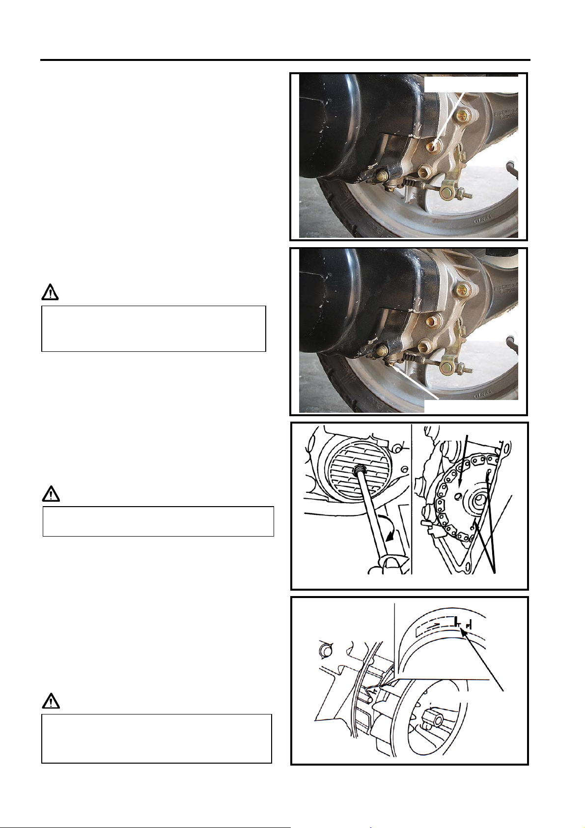
VALVE CLEARANCE ADJUSTMENT
Caution
Remove luggage box and front center cover.
Remove the left body cover & left side cover.
Remove cylinder head cap.
Remove the ignition timing check hole on the
cooling fan cover.
With “T” type wrench, turn crankshaft in
clockwise motion so that mark (“T”) on the
generator flywheel aligns with the mark on
the crankshaft, and camshaft is at TDC
position also as same as level of cylinder
head top-end. A single hole on camshaft
sprocket is forward to up. (Piston is at TDC
position in the compression stroke.)
Caution
Inspect if washer is in good condition.
Replace it with new one if it was
deformed or damaged.
Checks and adjustment must be performed
when engine is cold (below 35℃).
The crankshaft can not be rotated in
counter-clockwise to prevent from damage
so that valve clearance can not be
measured.
Ignition timing mark
TDC mark
Inspection hole
Gear oil refilling bolt
Gear oil draining plug

TGB 2. MAINTENANCE INFORMATION
2-5
Check & adjust valve clearance with feeler
gauge.
Valve clearance (IN/EX): 0.06±0.02 mm
Loosen fixing nut and turn the adjustment
nut for adjustment.
Caution
CARBURETOR IDLE SPEED
ADJUSTMENT
Caution
Park the motorcycle with main stand and
warn up engine.
Open the carburetor cover from the luggage
box.
Turn the throttle valve stopper screw to
specified idle speed.
Specified idle speed: 2200±100 rpm
Emission adjustment in Idle speed
Warm up the engine for around 10 minutes
and then conduct this adjustment.
1. Connect the tachometer onto engine.
2. Adjust the idle speed adjustment screw and
let engine runs in 2200±100 rpm.
3. Insert the exhaust sampling muffler of
exhaust analyzer into the front section of
exhaust pipe. Adjust the air adjustment
screw so that emission value in idle speed
is within standard.
4. Slightly accelerate the throttle valve and
release it immediately. Repeat this for
2~3 times.
5. Read engine RPM and value on the
exhaust analyzer. Repeat step 2 to step 4
procedures until measured value within
standard.
Emission standard: CO: below2.5±0.5 %
HC: below 800 ppm
It has to make sure that valve-rocker arm
is be adjusted to standard level when
adjusting it, and re-check the valve
clearance after tightened the fixing nut.
yInspection & adjustment for idle speed
have to be performed after all other
parts in engine that needed adjustment
have been adjusted.
yIdle speed check and adjustment have
to be done after engine is being warm
up (around 10 minutes).
Throttle valve stopper screw
I
g
nition coil cable
Air adjustment screw
Feeler gauge
Fixing nut

2. MAINTENANCE INFORMATION TGB
2-6
IGNITION SYSTEM
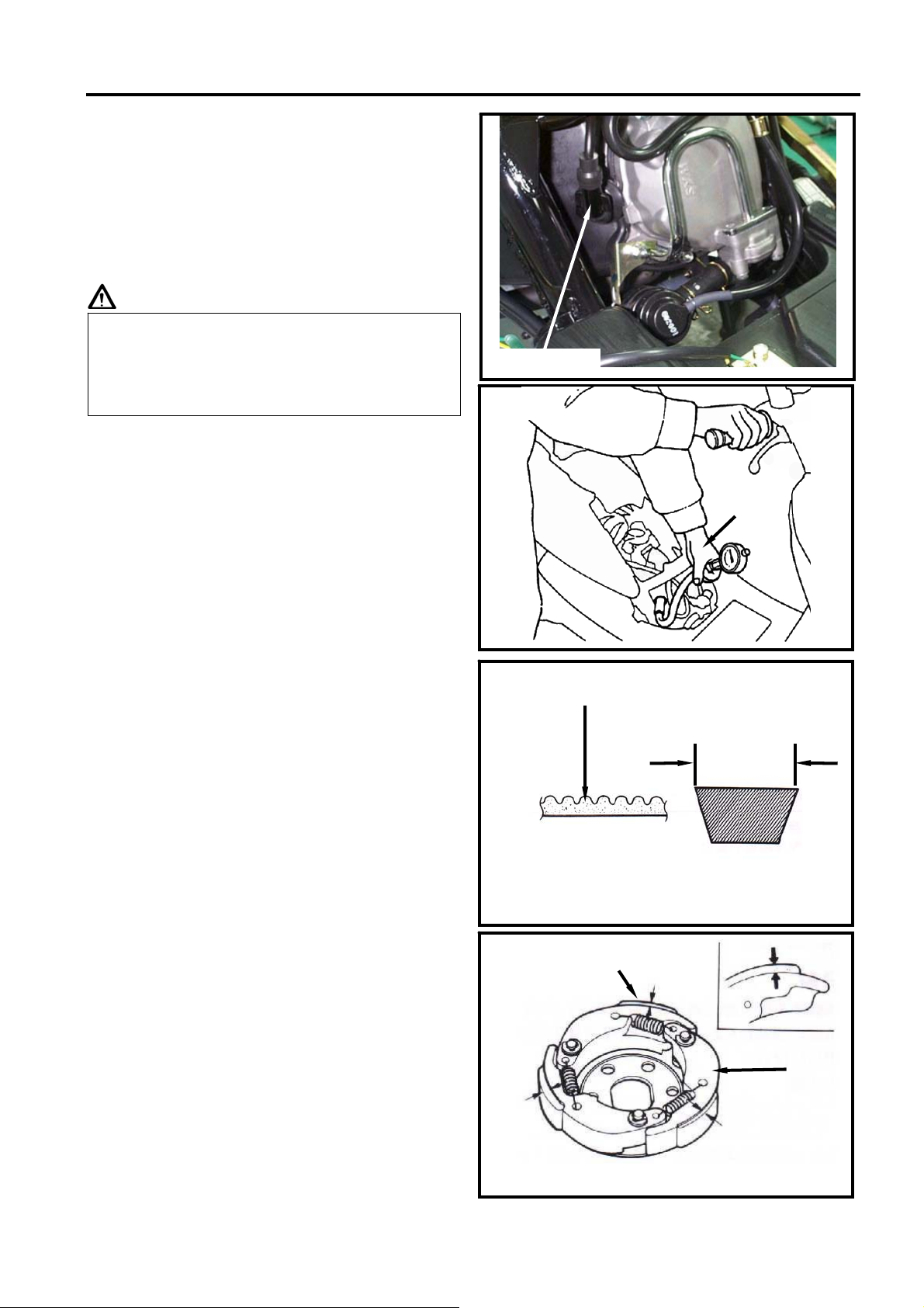
Ignition timing
Caution
Remove right side cover.
Remove ignition timing hole cap located on
the cooling fan cap, or remove the cooling
fan cap.
Check ignition timing with ignition light.
Start engine and set engine idle speed in
1700 rpm, and if the mark aligns with the “F”,
then it means that ignition timing is correct.
Increase engine speed to 8000 rpm to check
ignition timing advance. If the detent aligns
with advance mark “װ”, then it means ignition
timing advance is in functional. If not,
check CDI set, pulse flywheel, and pulse
generator. Replace these components if
malfunction of these parts are found.
SPARK PLUG
Appointed spark plug: TORCH A7RC
Remove luggage box.
Remove body side cover.
Remove spark plug cap.
Clean dirt around the spark plug hole.
Remove spark plug.
Measure spark plug gap.
Spark plug gap: 0.6~0.7 mm
Carefully bend ground electrode of the plug
to adjust the gap if necessary.
Screw the park plug into the plug hole with
hands, then tighten the plug with a wrench to
prevent from damaging the spark plug's
thread.
Torque value: 1.0~1.2 kgf-m
Connect spark plug cap.
C.D.I ignition system is set by
manufacturer so it can not be adjusted.
Ignition timing check procedure is for
checking whether C.D.I. function is in
normal or not.
I
g
nition li
g
ht
F mark
0.6~0.7mm
Side electrode Center electrode
Spark plug
TGB 2. MAINTENANCE INFORMATION
2-7
CYLINDER COPMRESSION PRESSURE
Warn up engine and then turnoff the engine.
Open the seat. Remove the luggage box.
Remove spark plug cap and spark plug.
Install compression gauge.
Full open the throttle valve, and rotate the
engine by means of stepping the
kick-starting lever.
Caution
Compression pressure: 12±2 Kg/cm²
Check following items if the pressure is too
low:
zIncorrect valve clearance
zValve leaking
zCylinder head leaking, piston, piston ring
and cylinder worn out
If the pressure is too high, it means carbon
deposits in combustion chamber or piston
head.
DRIVING SYSTEM
DRIVING BELT
Remove left side cover.
Remove mounting bolt located under air
cleaner.
Remove 9 bolts of the engine left crankcase.
Remove the left crankcase cover.
Check if the belt is crack or worn out.
Replace the belt if necessary or in accord
with the periodical maintenance schedule to
replace it.
Width limit: above 17.5 mm
Clutch pad
Start the motorcycle and gradually increase
throttle valve openness to check clutch pad
operation.
If the motorcycle moves with shaking, then
check its clutch pad for wearing. Replace it
if necessary.
Rotate the engine until the reading in the
gauge no more increasing.
Usually, the highest pressure reading will
be obtained in 4~7 seconds.
Gear teeth
Width
Cylinder
pressure gauge
Clutch
Clutch pad
Spark plug
TGB 3.LUBRICATIONSYSTEM
3-1
MECHANISM DIAGRAM....................3-1
OPERATIONAL PRECAUTIONS .......3-2
TROUBLE DIAGNOSIS......................3-2
ENGINE OIL.......................................3-3
CLEANING ENGINE OIL STRAINER...3-3
OIL PUMP............................................3-4
GEAR OIL ............................................3-7
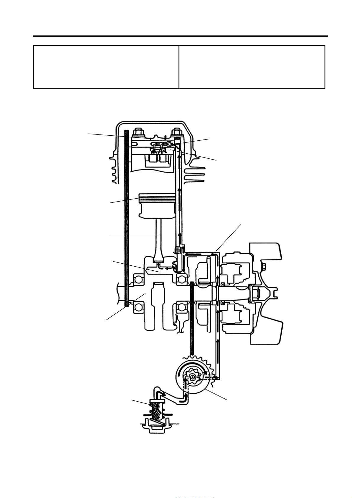
MECHANISM DIAGRAM
Valve rocker
arm
Camshaft
Scoop lubrication
Forcedly lubrication
Forcedly
lubrication
Inner passage
Connecting rod
Oil pump
Oil strainer
Crankshaft

3.LUBRICATIONSYSTEM TGB
3-2
OPERATIONAL PRECAUTIONS
General Information
zThis chapter contains maintenance operations for the engine oil pump, engine oil and
gear oil.
Specifications
Engine oil quantity Disassembly 850 c.c.
Replacement 750 c.c.
Oil viscosity SAE 10W-30 or equivalent
(Recommended King-Mate
serial oils)
Gear Oil Disassembly 120 c.c.
Replacement 110 c.c.
Oil viscosity of gear oil SAE 85W-140
(Recommended King-Mate
gear oil series SYM
HYPOID GEAR OIL)
unit : mm
Items Standard Limit
Inner rotor clearance - 0.12
Clearance between outer
rotor and body - 0.12
Oil pump Clearance between rotor
side and body 0.05~0.10 0.20
Torque value
Engine oil drain plug 3.5~4.5kgf-m
Engine oil screen cover 1.3~1.7kgf-m
Gear oil drain bolt 0.8~1.2kgf-m
Gear oil filling bolt 1.0~1.4kgf-m
Oil pump connection screw 0.1~0.3kgf-m
TROUBLE DIAGNOSIS
Low engine oil level
Oil leaking
Valve guide or seat worn out
Piston ring worn out
Low Oil Pressure
Low engine oil level
Clogged in oil strainer, circuits or pipes
Oil pump damage
Dirty oil
No oil change in periodical
Cylinder head gasket damage
Piston ring worn out
Oil viscosity

TGB 3.LUBRICATIONSYSTEM
3-3
ENGINE OIL
Turn off engine, and park the motorcycle in
flat ground with main stand.
Check oil level with oil dipstick after 3-5
minutes.
Do not rotate the dipstick into engine as
checking.
If oil level is nearly low level, fill out
recommended oil to upper level.
Oil Replacement
Caution
Place an oil pan under the motorcycle, and
remove oil strainer cap.
Make sure if the aluminum washer of the
draining bolt is damaged. If so, replace it
with new one.
Install the drain bolt and tighten it.
Torque value: 3.5~4.5 kgf-m
CLEANING ENGINE OIL STRAINER
Remove the oil strainer cap.
Remove oil strainer and spring.
Clean oil strainer (recommended using
compressed air to clean dirty foreign).
Check if the strainer and O-ring of the oil
strainer are broken. Replace with new one if
found.
Install the oil strainer and spring.
Install the oil strainer cap and tighten it.
Torque value: 1.3~1.7 kgf-m
Fill out oil to the oil filler (Oil viscosity SAE
10W-30) (Recommended King-Mate serial
oils).
Engine oil quantity: Replacement 850 c.c.
Drain oil as engine warmed up so that
make sure oil can be drained smoothly and
completely.
Oil
stra
i
ner cap
Dipstick
Oil drain plug
oil straine
r
spring
3.LUBRICATIONSYSTEM TGB
3-4
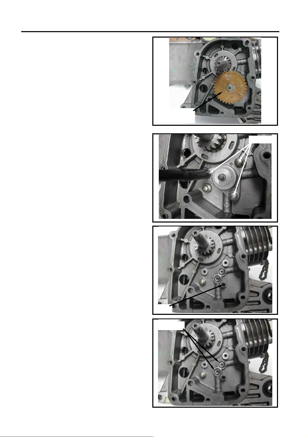
OIL PUMP
Oil Pump Removal
Remove the alternator (refer to chapter10).
Remove the engine right crankcase cover.
Make sure that the pump axle can be rotated
freely.
Remove the oil pump driving gear nut.
Remove oil pump body bolts (3 bolts).
Remove the oil pump pin.
Remove the oil pump.
Remove the 2 O-rings.
pump driving
gear nut
3bolts
pin
2 O-rings
This manual suits for next models
1
Table of contents
Other TGB Scooter manuals


