Thaler KE-SP 3050 User manual


Dear Customer,
We appreciate your purchase or rental of the Jakob Thaler KE-SP 3050 cable pulling winch.
You can expect this machine to function very effectively as we have designed it to operate and perform
with efficiency and to be maintained with ease.
This manual should be kept in the tool box, is an essential part of the equipment, and should always be
readily available.
This manual should also be made available to the following people:
- Machine operators
- Maintenance technicians
- Those who are transporting the machine
We recommend that all people involved in the project, whether in management, operation, or
maintenance, read the manual carefully and completely before the use of the winch. Please contact us for
any clarification and/or additional information you may need.
We recommend that all rules and regulations prescribed by the company and the country where the
winch is being used be observed, in addition to the methods prescribed here for handling, usage and
maintenance of the winch.
Thank you,
Jakob Thaler GmbH Global Machinery
Cable Laying Machinery and Equipment Cable Placing Equipment
Manufacturer USA Distributor

General Safety Instructions
This manual has been prepared to assist you in the operation and
care of your new winch. Please read it thoroughly as the contents
can contribute to more effective operation of your equipment.
The construction of this winch including the mechanical, hydraulic and electrical systems, were all designed
to meet safety standards of European Union No 98/37/EC.
The winch should be operated and handled by qualified personnel only. Qualified operators are those who
have received training from the machine owner’s company or, alternatively, from the manufacturer. Never
permit anyone to operate the winch without proper training.
Operators must be aware of all local, state and federal safety regulations governing the use of this
equipment.
Operators must wear suitable clothing to reduce the possibility of entanglement in the machine’s moving
parts. They should avoid the wearing of any jewellery for the same reason.
Operators must use personal protective gear in accordance with OSHA’s PPE guidelines. (Safety glasses,
gloves, boots, hard hat, etc.)
Operators must carefully follow hazard related instructions contained in this instruction manual or indicated
on the machine.
The work area should be clear of oil or other liquid spills, as well as materials or equipment that may be
considered an obstacle to proper operation.
The operator must avoid the direct inhalation of the equipment’s engine exhaust.
The winch must not be modified without the specific and written consent of the Manufacturer. Factory
provided accessories and spare parts must always be used.
All maintenance and repairs, including electrical, should be performed by trained and authorized personnel
only. Any waste oils, grease or fuel should be disposed of properly in accordance with the local state or
country guidelines.
Note
These units are built according to your order and the latest design changes. Therefore, differences in the descriptions and pictures
of the equipment may occur as they apply to your machine. We reserve the right to make design changes at any time and without
notice.

Safety Instructions
Standard Operation:
Before starting the job:
-Secure the work area (traffic, manhole, etc.).
-Ensure all safety equipment is in place and operating correctly.
-Be sure that the winch has been stabilized properly.
-Before starting the operation, be sure that no one is standing in the operation area.
-Test the operation of all controls according to the instructions in this manual.
Maintenance:
-Only to be performed by trained personnel.
Danger!
-If the safety devices have been removed for maintenance purposes, operate the machine with
utmost care.
-Refer to the maintenance instructions in this manual.
-Safety devices must be immediately re-installed after maintenance has been completed.

Table of Contents
1 Product Information
1.1 Machine Description..................................................................................................................... 1
1.2 Manufacturer................................................................................................................................. 1
1.3 CE-certification............................................................................................................................. 1
1.4 Application According to Design................................................................................................. 1
1.4.1 Use / Operation Range................................................................................................................. 1
1.5 Operator Station........................................................................................................................... 2
1.6 Technical Data............................................................................................................................... 2
1.7 Product Description...................................................................................................................... 3
2 Transport of the Winch
2.1 Securing the Trailer to the Tow Vehicle..................................................................................... 4
2.1.1 Traffic Regulations....................................................................................................................... 4
2.1.2 Connecting the Trailer.................................................................................................................. 4
2.2 Driving with the Winch................................................................................................................. 6
2.2.1 Forward Movement....................................................................................................................... 6
2.3 Disconnecting the Winch............................................................................................................. 7
2.4 Moving the Winch Manually......................................................................................................... 7
2.5 Changing Tires and Adjusting Tire Pressure.............................................................................. 7
3 Operation of the Winch
3.1 Rear Supports.............................................................................................................................. 9
3.2 Boom Control (Hydraulic Boom)............................................................................................... 10
3.3 Description of Control Panel Components............................................................................... 11
4 Maintenance................................................................................................................................ 16
4.1 Scheduled Maintenance............................................................................................................. 17
4.2 Hydraulic System........................................................................................................................ 18
4.2.1 Checking the Hydraulic Oil Level.............................................................................................. 18
4.2.2 Breather in Filler Cap of Hydraulic Oil Tank............................................................................. 18
4.2.3 Changing the Hydraulic Oil........................................................................................................ 18
4.2.4 Filter Change............................................................................................................................... 18
4.2.5 Regular Control Checks............................................................................................................. 18
4.3 Greasing...................................................................................................................................... 19
4.4 Rope Inspection and Replacement........................................................................................... 19
4.5 Drive Chain and Chain Wheels.................................................................................................. 19
4.6 Check Operation Controls for Proper Function....................................................................... 19
4.7 Maintenance of Yanmar Diesel Engine..................................................................................... 19
Maintenance Schedule............................................................................................................... 20
5 Troubleshooting Guide
5.1 Diesel Engine.............................................................................................................................. 21
5.2 Trailer Electric Brake System.................................................................................................... 21
Service and Warranty Conditions………………………………………………………………….… 22
Attachments:
-Operation and Maintenance Manual for Yanmar Engine
-Spare Parts List
-Electric and Hydraulic Schematics
Page 1
1 Product Information
1.1 Machine Description: Cable Pulling Winch
Model: KE-SP 3050
1.2 Manufacturer: Distributor USA:
Jakob Thaler GmbH Global Machinery
Cable Laying Machinery and Equipment 705 West 62nd Ave.
Justus-von-Liebig-Str. 8 a Denver, CO 80216
D-25335 Elmshorn / Germany (303) 430-7130
Tel. +49(0)4121/57999-0 (800) 430-7130
Fax +49(0)4121/5799957 Fax (303) 428-7762
1.3 CE-certification:
This machine has a
sticker, which is fixed on the serial number plate.
1.4 Application According to Design:
This cable-pulling winch should only be used per the operation manual and the following safety
guidelines.
1.4.1 Use / Operation Range:
The Cable Capstan Winch Model KE-SP 3050 is designed to pull in empty duct and cable in a
horizontal direction up to a pulling force of 11000 pounds, 50 kN.
This machine is only to be used for the work it was designed for.
If the unit is used for other applications or working conditions, prior
consultation with the manufacturer is required.
If this caution is not followed, the manufacturer is free from any liability for
damages or losses incurred.
While operating the machine, all warning signs and decals must be obeyed.
The Cable Capstan Winch must not be used:
• For lifting people and/or goods
• In a location where the machine cannot be positioned and anchored properly
• In areas where brush or other materials can be easily set on fire
• In closed/unventilated sites, or those poorly ventilated (tunnel or similar)
• At sites where fuels or explosives are present
• For structure demolition
• For the pulling of elastic elements
• With ropes or joints having a bigger diameter than that specified in this manual
• With over-ridden or broken safety system devices
• For handling trucks or other mobile equipment

Page 2
1.5 Operator Station:
The operator must stand in an area that is free and clear of all moving parts while the unit is in
operation.
1.6 Technical Data:
VIN / Serial Number : ___________________________________
Delivery Date : January 9, 2013
Drive : 3 Cylinder Diesel / Yanmar 3TNV88
Power : 36 HP (27.1 kW)
Max. Pulling Force : 11000 pounds (50 kN)
Max. Pulling Speed : 0-220 fpm, continuously adjustable
Rope Diameter : 0.472 inches (12 mm)
Rope Length : 2500 feet (765 m)
Overall Length (including tongue) : 157-1/2 inches (4000 mm)
Width : 67 inches (1700 mm)
Height : 67-1/2 inches (1710 mm)
Tires : 215/75R 17.5
Electrical : 12 V

Page 3
1.7 Product Description:
This cable capstan winch represents the latest modern technical standard in the area of
hydraulically operated cable pulling winches. It is specifically designed for pulling in and out
communication and power cables of all types.
The winch is designed for pulling horizontally. It is NOT to be used as a means for lifting loads.
The single axle chassis consists of a rubber suspension axle with electric brakes. The hitch is
height adjustable and equipped with a forged 4-bolt mount hitch. A crank jack is fitted to the trailer
tongue. The tire size is 215/75R 17.5. The lighting system is 12 Volt.
Rear adjustable stabilizers control the stability of this winch during the pulling operation. For
transportation the stabilizers may be raised up and be secured with the appropriate pins.
The capstan unit is hydraulically driven. The power pack consists of a 36HP (27.1 kW) water-cooled
diesel engine (corresponding to the EPA norms) and a pressure and flow controlled hydraulic pump.
The steel wire rope of the winch runs directly from the capstan system to the rope drum. The
machine is equipped with an automatic level-wind system with cross groove spindles so that even
layering of the rope onto the rope drum is guaranteed.
Drive and brake operation of the drum is powered hydraulically.
The boom is hydraulically raised and lowered, manually pivoted +/-45° laterally and is secured by
a manually adjusted boom support.
The measurement of the pulling force is controlled and monitored by an electronic measuring
system (KPR 2000) with a record printer mounted at the control panel. The measuring system
has the following functions:
- Indication of pulling force, length and pulling speed
- Adjustable maximum pulling force limit with automatic stopping function of the winch drive
system when the adjusted pulling force is exceeded
- The ability to print out a complete pull report while in the field
The separate card writer is connected to the KPR 2000 system by a serial cable and has a 32 MB
storage card with card adaptor for storing cable pull data.
By pushing a single button at the KPR 2000, each job can be stored on the card as MS-
DOS/Windows compatible data. A name for each pulling job is automatically generated. The data
can be evaluated on a PC or Laptop and shown in tabular form. If the data is required in graphic
form, it can be opened in Excel for analysis.
All operator controls are centrally mounted at the operation panel. The following controls exist:
- Remote control joystick with deadman switch for controlling the pulling direction and speed
-Throttle lever for engine speed
- Key-operated switch for engine start
- Control indicators for diesel engine
- Fuel gauge
- Working hour meter
- Electronic measuring system (KPR 2000)
- Card-writer with adaptor
- Raise/Lower lever for hydraulic boom
- On/Off switch for rotating beacon light
Page 4
2. Transport of the Winch
The winch is mounted on a single axle trailer chassis fitted with an electric brake system and a
height adjustable hitch.
2.1 Securing the Trailer to the Tow Vehicle:
2.1.1 Traffic Regulations:
Based on local state and country laws, select the appropriate vehicle for the transportation of the
winch.
2.1.2 Connecting the Trailer:
Note that unless the winch is secured against movement, no person is
allowed to stand between the pulling vehicle and the winch.
The hitch of the trailer must be adjusted to the hitch height of the pulling vehicle.
Proper selection and condition of the hitch type and size are essential to
safely towing your winch. A loss of coupling may result in death or serious
injury.
•Be sure the hitch load rating is equal to or greater than the load rating
of the coupler.
•Be sure the hitch size matches the coupler size.
•Observe the hitch for wear, corrosion and cracks before connecting.
Replace worn, corroded or cracked hitch components before
coupling the winch to the tow vehicle.
Be sure the hitch components are tight before coupling the winch to the tow
vehicle.
Height adjustment of the hitch
Hitch height should be adjusted only when the winch is not connected to the
towing vehicle.
Secure the winch against movement!
The hitch can be adjusted in the range of
2.165 inches (55 mm) steps.
Bolts (M16) have to be tightened by a
torque wrench to 155 ft. pounds (210Nm)

Page 5
Coupling
- Prepare the winch for transport
- Secure the trailer from moving by the use of wheel chocks
- Release and open the tow vehicle’s hitch coupling
- Backup the tow vehicle until the coupling is aligned
- Lock coupling around eye on trailer
An improperly coupled winch can result in death or serious injury.
Do not move the winch until:
•The coupler is secured and locked to hitch;
•The safety chains are secured to the tow vehicle;
•The supporting jack is fully retracted; and
•The wheel chocks are stored and secured.
Do not tow the winch on the road until:
•Tires and wheels are checked;
•The winch brakes are checked;
•The breakaway switch is connected to the tow vehicle; and
•The winch lights are connected and checked.
If your winch comes loose from the hitch for any reason, safety chains have been provided, so
that control of the winch can still be maintained.
Improper rigging of the safety chain system can result in loss of control of
the winch and tow vehicle, leading to death or serious injury, if the winch
becomes uncoupled from the tow vehicle.
•Fasten the safety chains to the frame of the tow vehicle. Do not fasten the
safety chains to any part of the hitch, unless the hitch has holes or loops
specifically designed for that purpose.
•Cross the safety chains underneath the hitch and coupler with enough
slack to permit turning while transporting, and to hold the tongue up,
should the winch come loose.
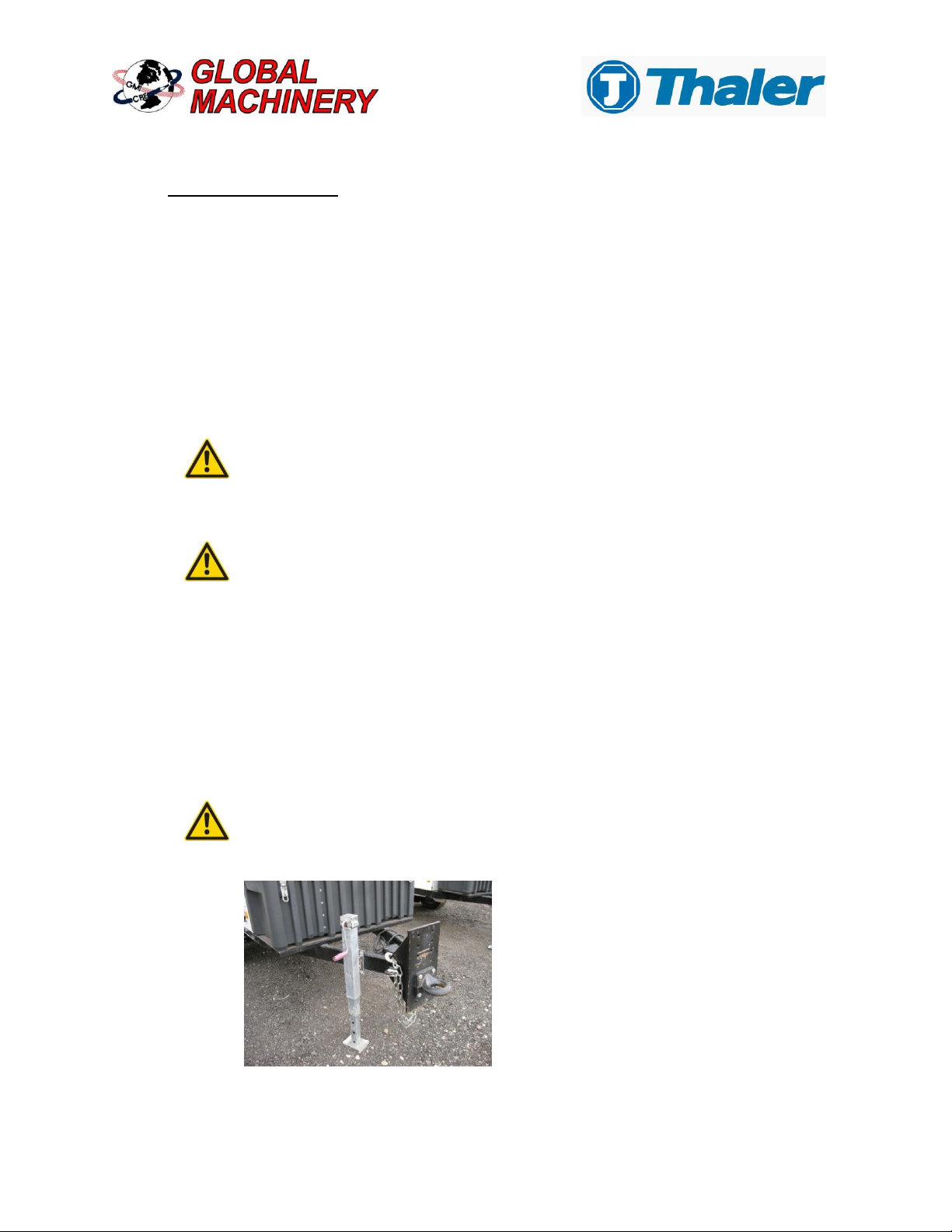
- Completely crank the jack upward until it engages, then fasten it with the safety pin.
The jack is only intended to provide support. Do not manoeuvre the winch if
the jack is lowered. This can cause injury and even death. Make sure that the
front jack is fully raised and secured.
- Secure the wheel chocks.
- Plug in the electrical connecting cable to the pulling vehicle. Use an adapter plug if necessary.
- Examine the lights of the winch for proper functioning.
Before each time this trailer is towed:
-Check the lighting system.
-Check tire conditions (tire pressure, damage).
-Check to be sure the winch is correctly coupled and the jack is fully raised and secured.
-Check the operation of the electric brake system

Page 6
2.2 Driving with the Winch:
The following actions must be avoided:
- Driving over curbs
- Exceeding the allowable maximum speed
- Mounting of non-acceptable wheels/tires
2.2.1 Forward Movement:
If a winch is connected, the tow vehicle is under more stress; therefore the driver has to pay closer
attention. If the driver is not able to see the rear traffic by use of the normal rear-view mirrors of the
tow vehicle, additional mirrors are required. The additional load of the winch reduces the maximum
allowable load of the pulling vehicle. Take extra caution while driving mountain roads.
Laws and regulations of the countries where the unit is being used shall be observed regarding
supporting loads and maximum speeds for trailers being pulled by tow vehicles. The maximum
speed for this unit is 65mph. Even if your country allows higher speeds, you should not exceed
65mph for safety reasons.
Increasing the speed reduces the stability of the vehicle, especially in bad weather road conditions.
Therefore, you should adjust your speed to accommodate driving conditions. In any situation, if the
trailer becomes unstable or starts to sway, the speed must be reduced. Do not increase the speed.
Always remember to brake in time! Leave plenty of room between you and the vehicle in front of
you.
Page 7
2.3 Disconnecting the Winch:
Danger!
Uncoupling the winch without the use of wheel chocks may result in the
winch rolling away and potential injury or damage. Always use wheel chocks
under the wheels when disconnecting the winch.
Damage!
Remove the break-away cable and the trailer plug. Otherwise, damage to the
cable or plug may occur when the tow vehicle is pulled away from the trailer.
Make sure that the towing vehicle is properly uncoupled before driving away.
Place the wheel chocks under the wheels so that the winch is secured against rolling away. Release
the pin, lower the jack leg, and crank down the jack. Unplug the trailer plug cable and the break-
away cable from the towing vehicle. Store the cable into its holder, in order to protect the contacts
from dirt. Unhook the safety chains. Store the safety chains so that they do not hang on the ground.
Pull up the hitch lever and uncouple the winch by cranking the jack leg down. It is now safe to drive
away the towing vehicle.
2.4 Moving the Winch Manually:
If the winch rolls, DO NOT try to move it manually!
In a low light environment, or if weather conditions demand (for example in fog), the winch should
not be parked without lighting systems. Any further legal regulations have to be taken into
consideration.
2.5 Changing Tires and Adjusting Tire Pressure:
Danger!
If the winch is not secured against movement and starts to slip, and therefore
falls off the jack, a person can be injured, potentially causing death. Secure
the trailer against movement when changing the tires.
Danger!
If a person is under the vehicle during the wheel change and the winch falls
off the jack or the jack fails, the person can be injured, potentially resulting in
death. It is forbidden to be under the lifted vehicle without jack stands or
other safety equipment to secure the winch.
Worn tires do not grip wet roads very well at high speeds and there is a higher risk of hydroplaning.
It is recommended that tires be changed when worn beyond serviceable condition.

Page 8
Set the winch on a flat, horizontal, solid surface.
Use an appropriate jack.
Disconnect the winch from the towing vehicle.
Secure the winch against rolling away with the wheel chocks
on the side of the winch where the tires are intact.
Do not lie under the lifted vehicle without additional and
appropriate support.
Position the jack on the axle as close as possible to the wheel
being changed.
Follow the instructions of the jack manufacturer.
Remove the wheel nuts. Replace the wheel. Snug the wheel nuts. Lower the winch and tighten
the wheel nuts cross-wise with a torque wrench.
After the first 30 miles (50 km) of use, and after every wheel change, the wheel
nuts have to be checked and tightened if necessary.
Starting torque of wheel nuts:
See AL-KO Owner’s Manual for torque specifications.
Recommended tire pressure:
215/75R 17.5 - See tire sidewall for recommended pressure.
The tire pressure should be checked at least once a week, and corrected if necessary. The pressure
should be checked while the tires are cold.

Page 9
3. Operation of the Winch
Only work with the winch when it is in good operable condition. Always be aware of safety
precautions and machine damage that may adversely affect the machine’s operation.
Damages or defects to the winch must be immediately reported to a responsible person.
Damages or defects to the winch should be repaired before using the unit.
Be sure that only trained personnel operate the winch. Regular winch inspections at
scheduled intervals should be conducted with a focus on safety and damage.
3.1 Rear Supports
1 2 3
Pos. 1 Rear supports
The rear supports are used for supporting the winch during operation, and are adjustable by pins
and crank.
Pos. 2 Safety pins
The safety pins secure the rear supports of the winch. Pull out the safety pins, adjust the rear
support lengths, and secure them by reinserting the safety pins and keepers.
Pos. 3 Wheel chocks
Put the wheel chocks in front or rear of the tire to secure the winch against movement.
Always use both wheel chocks to secure the winch against movement.
The wheel chocks may also be used to stabilize the winch while pulling in the cable.

Page 10
3.2 Boom Control (Hydraulic Boom)
After removing and stowing the boom transport support arm, the boom can be hydraulically
raised and lowered. It can be manually pivoted laterally +/- 45° and pinned in place. It is vertically
supported by a manually adjusted boom support jack.
Always support the boom with the support jack to prevent damage to the boom.
The boom control lever hydraulically adjusts the height of the boom.
Adjustable boom lock is used to secure the boom when unit is
being transported. The boom lock must be secured when transporting to prevent boom damage.
Latch used to disconnect ball coupler from boom when hydraulically
lowering boom. Reverse procedure to secure boom for transport.
Three cornered locking nut used to tighten adjustable link from rotating. Loosen nut and rotate black
adjustment arm to unlatch boom lock ball end. Do the opposite when installing the ball to secure arm.
Page 11
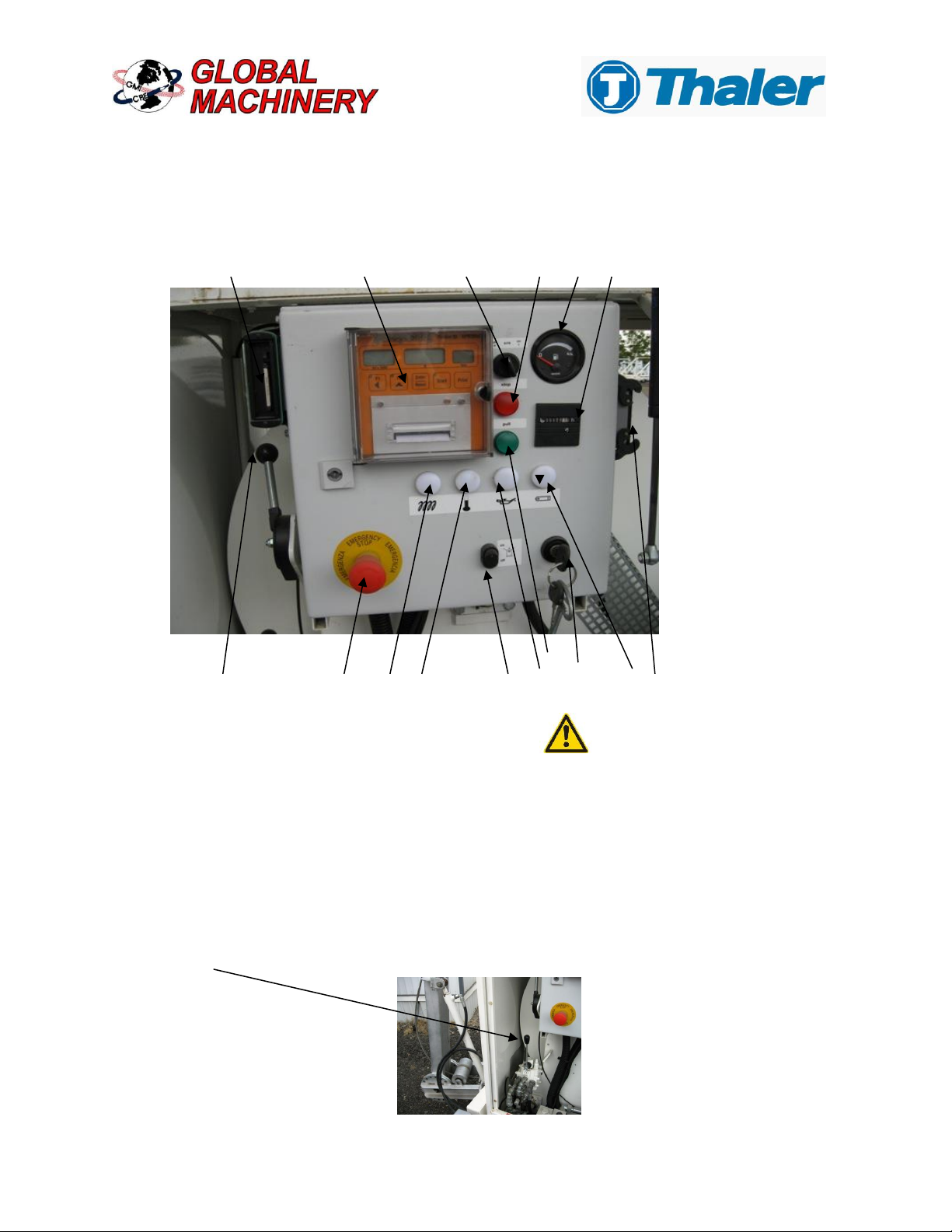
3.3 Description of Control Panel Components
17 9 8 3 15 10
2
1
5 4 14 13 16 12 11 6
Pos.
1
Ignition switch with 3 settings - Turn to the right
2
Control Light, Green - Operation
3
Control Light, Red - Stop
4
Emergency Stop Button
5
Throttle lever - Engine Speed
6
Remote control tether plug connection
7
Remote control with dead-man switch (stored in toolbox, not shown)
8
On/off switch for electronic measuring system (KPR 2000)
9
Electronic Measuring System (KPR 2000)
10
Hour meter (counter)
11
Indicator light for alternator
12
Check oil indicator light
13
Control light –Engine temperature monitoring
14
Control light –Engine preheat
15
Fuel gauge
16
Switch for rotating beacon (on/off)
17
Card recorder
18 Boom control lever (hydraulically raise & lower boom)
•Proper functioning of safety
systems should be verified
daily.
•Never remove any safety
devices!
•Do NOT touch the machine
while running!
•Make sure that no
unauthorized personnel
operate the winch!
Page 12
Description of components:
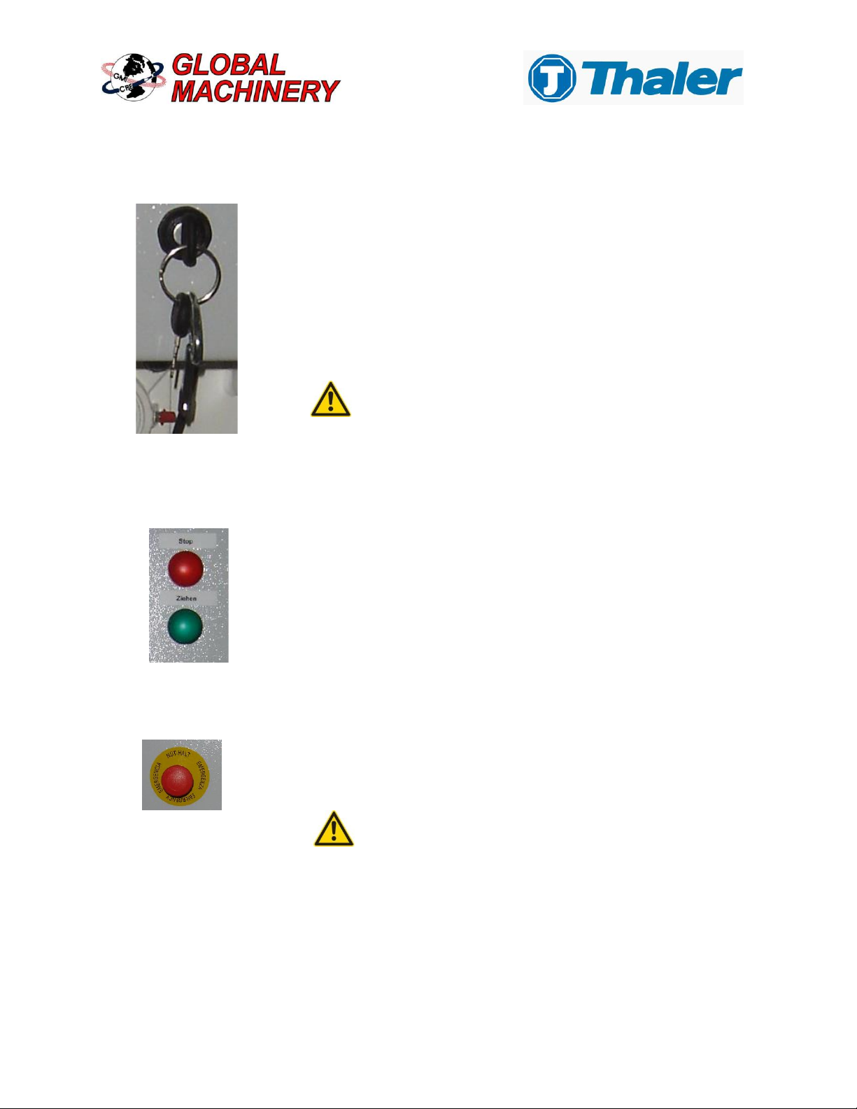
Pos. 1 Ignition switch with 3 settings - Turn to the right
To start the engine, set the throttle lever (5) into medium speed
position. Set the winching lever (6) into “zero-position”
-Turn the ignition key clockwise until the control lights switch on.
-Turn the key to the next stage to activate the glow plugs for
the diesel engine. Control light (14) should be on.
-When the light goes off, turn the key to the next stage and
the engine will start. Disengage the key as soon as the
engine starts to run.
Never leave the ignition key in the start position for
longer than 10 seconds in order to save battery life
and starter wear.
Never turn the ignition key to “start” when the
engine is running.
Control lights 11 and 12 should turn off when the engine runs.
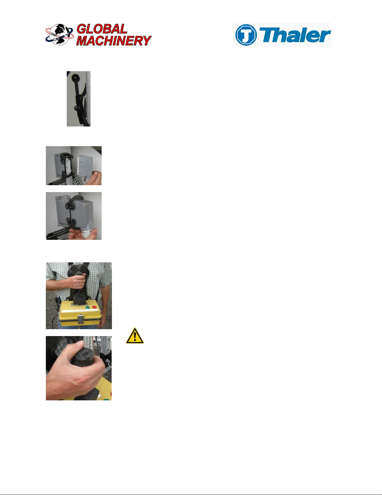
Pos. 3 Control Light, Red - Stop
The red control light is switched on when the Emergency Stop button is
pressed, the dead-man´s switch is not pushed, or the set maximum limits
of the KPR 2000 has been reached and stopped the winching process.
Pos. 2 Control Light, Green - Operation
The green control light indicates proper function of the electric control
circuit.
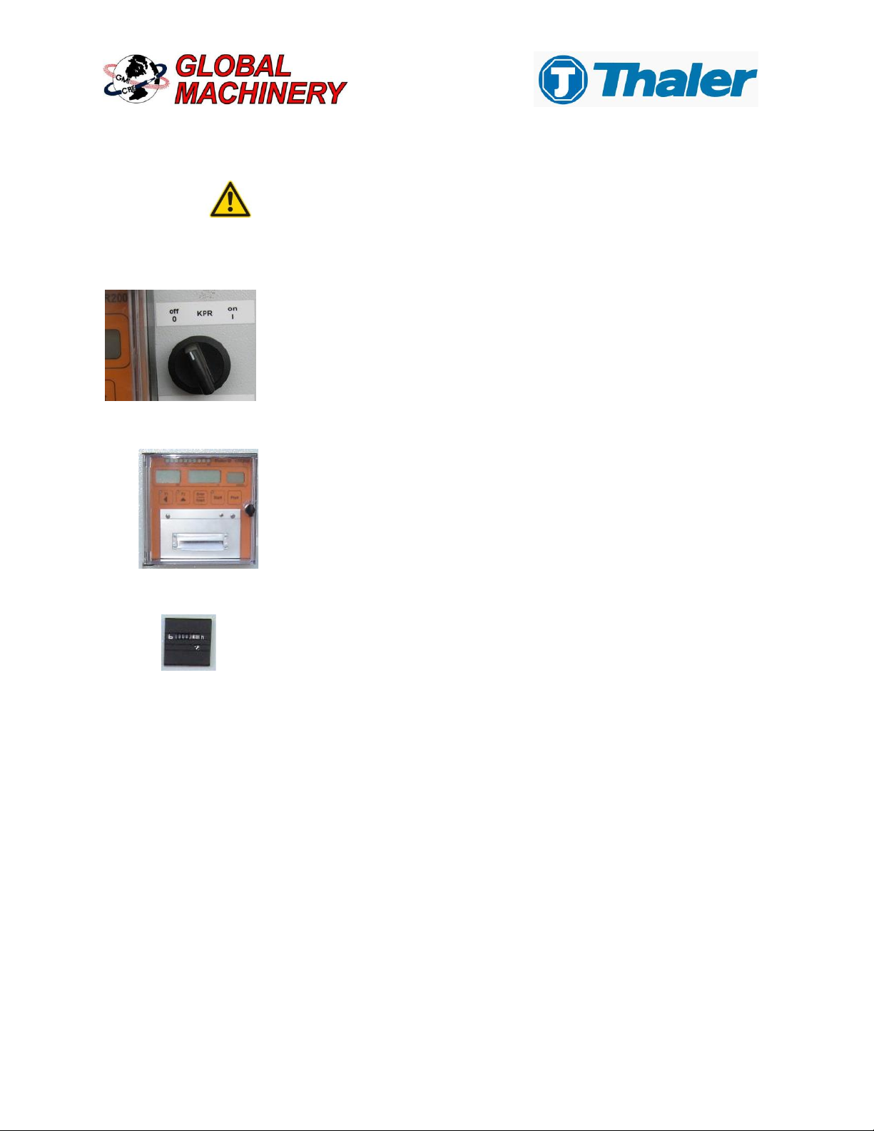
Pos. 4 Emergency Stop Button
When the emergency stop button is pressed, the winching function will
be stopped immediately. Reset by turning left.
Caution
Use of the emergency stop is ONLY recommended in
emergency situations. It is NOT recommended to use
the emergency stop system for normal shut down of
the system.
Pos. 6 Tether connection for remote control
Secure with two latches.
Pos. 7 Remote Control
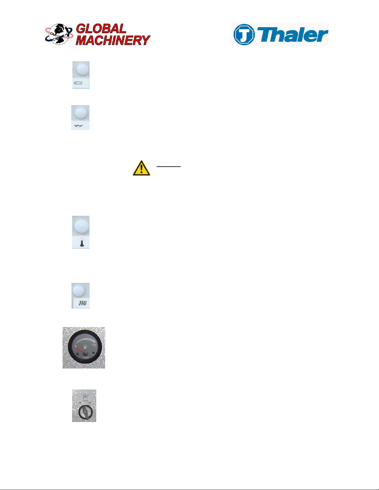
Pos. 5 Throttle lever - Engine Speed Page 13
This lever regulates the speed of the diesel engine. Start the cold
engine at approximately half speed. When the operation temperature is
reached, adjust the speed to full throttle during pulling operation.
Insert remote control cable plug into connection.
Clean connections as needed and lube with dielectric grease.
To pay-out the wire rope, push the lever right while holding down the
dead-man switch on top of the lever. For pulling-in, move lever left
while holding down the dead-man switch. The amount you move the
lever increases or decreases the line speed.
When winching in, position the lever so that there is a balance
between pulling force and line speed. Otherwise, the engine may
stall.
The toggle switch on the remote control lever must always be held
on for winching in or out. Pay-out the rope the distance required, or until the
color-marked end of rope appears. Stop pulling out immediately to avoid
pulling the rope off the capstan unit.
If the Emergency-Stop is pressed (or if the set value of the measuring
system - pulling force and/or length –are exceeded and the winching
operation is stopped automatically) this lever must be set back to the
“Zero” position to allow a re-start of the winching function.
Page 14
Report any wire rope damage immediately. Refer to Section 4.4 of the
maintenance manual for detailed inspection procedure.
Pos. 8 On/Off switch for Electronic Measuring System (KPR 2000)
Pos. 9 Electronic Measuring System (KPR 2000)
To learn how to operate the KPR 2000, please read the detailed
description in the KPR 2000 manual.
Pos. 10 Hour meter (counter)
The working hour counter displays the accrued operation hours of the
winch. This is important for maintenance intervals.
For monitoring the winching process with the KPR 2000, be certain the
switch is turned to the ON position.
Pos.11 Indicator light for alternator
The light should be off when the engine is running. If not, stop the
engine immediately. The electric circuit needs to be checked by a
specialist.
Pos.12 Check oil indicator light
This light must be off when the engine is running. If not, the engine must
be stopped immediately. Check the engine oil level.
If required, top off the oil level. Start the engine again. If the control light
still illuminates, contact a dealer for the engine manufacturer.
DO NOT try to start the engine if the indicator light
illuminates again. Damage or destruction of the engine
may occur.
Page 15
Pos.13 Control light –Engine temperature monitoring
This indicator light illuminates when the engine temperature is too high.
Turn off the engine immediately and check the following:
1) Coolant level in radiator overflow tank.
2) Obstructions in radiator.
3) Damage to fan belt.
Pos.14 Control light –Engine preheat
This indicator light for the glow plug must be off before starting the
diesel engine.
Pos. 15 Fuel gauge
The fuel gauge is equipped with a precise rotation measuring unit that
accurately shows the fuel level of a fuel tank as measured by the
sensor.
Check the fuel level before starting the diesel engine.
Pos. 16 Switch for rotating beacon (on/off)
By operating this switch the beacons are turned on and off.
Table of contents


