The Frank G. Hough HA PAYLOADER Installation and user guide

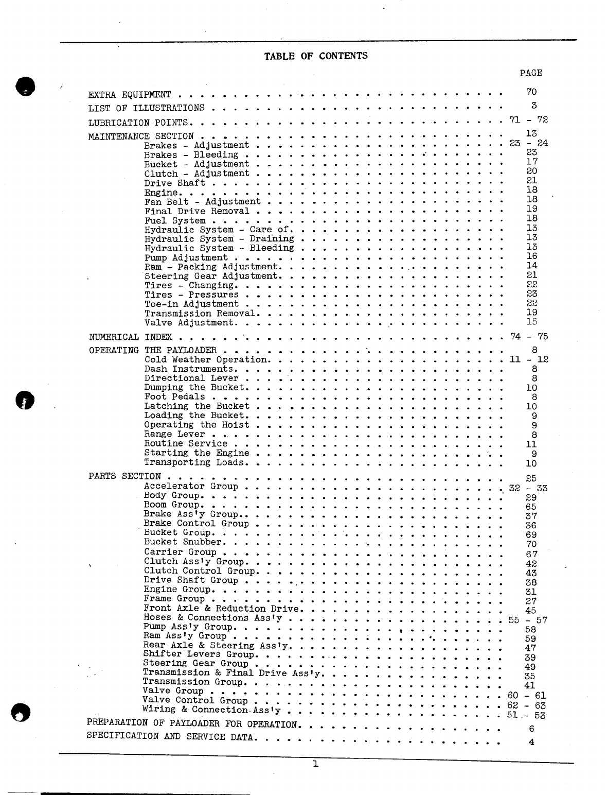
TABLE OF CONTENTS
o
MAINTENANCE SECTION • •
Brakes - Adjustment
Brakes - Bleeding •
Bucket - Adjustment
Clutch - Adjustment
Drive Shaft . • . •
Engine. • • • . • • • •
Fan Belt - Adjustment ••••
Final Drive Removal •
Fuel System • • • • • • •
Hydraulic System Care of.
Hydraulic System - Draining
Hydraulic System - Bleeding
Pump Adjustment . • • • •
Ram - Packing Adjustment.
Steering Gear Adjustment •••••
Tires - Changing •••
Tires - Pressures • •
Toe-in Adjustment • •
Transmission Removal.
Valve Adjustment .•••••
NUMERICAL INDEX • • • • • • ", •
OPERATING THE PAYLOADER • • • •
Cold Weather Operation. •
Dash Instruments •••
Directional Lever •
Dumping the Bucket.
Foot Pedals • • • •
Latching the Bucket •
Loading the Bucket ••
Operating the Hoist •
Range Lever • •.• • •
Routine Service • •
Starting the Engine •
Transporting Loads.
PARTS SECTION • • . •
Accelerator Group • •
Body Group ••••.
Boom Group •• , ••
Brake Assly Group ••
Brake Control Group •
.Bucket Group. .,, .
Bucket Snubber, , .
Carrier Group • • • • •
Clutch Assly Group ••
Clutch Control Group.
Drive Shaft Group ••
Engine Group ••••.•
Frame Group • • • • •
Front Axle
&
Reduction Drive.
Hoses
&
Connections Assly •
Pump Assly Group •.••••
Ram Assly Group ••••••
Rear Axle
&
Steering Ass'Y.
Shifter Levers Group. • • .
Steering Gear Group • • • •• •
Transmission
&
Final Drive Assly.
Transmission Group ••.•
Valve Group • • • • • • • ••
Valve Control Group • • • • • •
Wiring
&
Connection.Assly •••
PREPARATION OF PAYLOADER FOR OPERATION.
SPECIFICATION AND SERVICE DATA. • • • •
.
..
PAGE
70
3
71
- 72
13
23 - 24
23
17
20
21
18
18
19
18
13
13
13
16
14
21
22
23
22
19
15
74 - 75
EXTRA EQUIPMENT • • •
LIST OF ILLUSTRATIONS
LUBRICATION POINTS ••
•• 11
8
- 12
8
8
10
8
10
9
9
8
11
9
10
-,
25
•.32 - 33
29
65
37
36
69
70
67
42
43
38
31
27
. • .• 45
• 55 - 57
58
59
47
39
49
35
• • •• 41
• • 60 - 61
• 62 - 63
51.- 53
.,
,
.
.
6
4
1
u
•
J
2

LIST OF ILLUSTRATIONS
Accelerator Group
Body Group ••••
Boom Group. . . • •
Brake Control • •
Brake Drum Group.
Brake Pedal Adjustment.
Brake Shoe Adjustment
Bucket Group •••••
Carrier Group • • • . .
Clutch Group. • • • • .
Clutch Control Group .•
Clutch Pedal Adjustment
Clutch Section. •
Control Levers ••
Dash Instruments ••
Drive Shaft • • • ,
Engine Group. . . •
Final Drive Removal
Frame Group • . • •
Front Axle Reduction Drive.
Hydraulic Diagram •
Lubrication Chart •
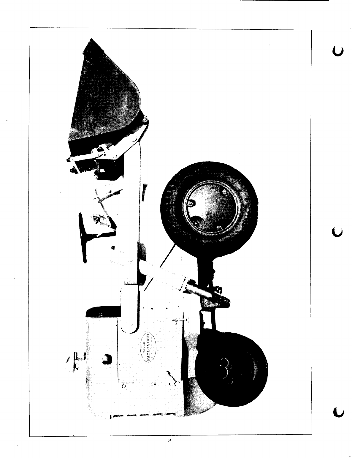
Payloader Side View
Pump Assembly •
Pump Group •••..
Ram Section • • • •
Ram Group ••.•••
Rear Axle
&
Steering Group.
Shifter Levers Group ••••
Steering Gear Group . . • •
Steering Gear Adjustment •.
Transmission
&
Final Drive Group ••
Transmission Group.
Valve Group • • . .
Valve Control Group
Valve Section . •
Wiring Diagram. '••
PAGE
32 - 33
28
64
36
37
24
23
68
66
42
43
21
20
7
7
38
30
19
26
44
54 - 56
73
2
16 - 17
58
14
59
46
39
48
• 21 - 22
34
40
60 - 61
• 62 - 63
•• 15 - 16
• 50 - 52
3

CONDENSED SPECIFICATIONS ~& SERVI CE DATA
ENGINE
No. Cylinders
Bore .
Stroke .
Displacement .
Speed (Governed).
Horse Power .
4
3-1/4"
4"
133 cu. in.
1800 R.P.M.
29
Complete with electrical starting equipment, oil bath air cleaner
with centrifugal type pre-cleaner and engine oil filter.
TRANSMISSION
HOUGH two speeds forward and two speeds reverse, completely
equipped with anti-friction ball bearings.
Low
High
FORWARD
2.5 to 1
1 to 1
REVERSE
1.53 to 1 (Reduction)
1.64 to 1 (step up)
GEAR RATIOS:
FINAL DRIVE:
HOUGH heavy duty double reduction spiral bevel and spur gear de-
sign. First reduction spiral bevel with differential ahead of final
drive. Full floating axle shafts. Completely equipped with ball and
roller bearings.
GEAR RATIO:
22
to
1
PAYLOADER SPEEDS, MILES PER HOUR (ENGINE AT 1800 R.P.M.)
TRAVELING SPEEDS: FORWARD REVERSE
Low
High
2.5
10.0 3.5
11.0
CAPACITIES:
Cooling System . .
Fuel Tank. . . . .
Transmission Case.
Final Drive Case
Crankcase ....
Hoist Reservo:!-r.
3-1/2 gal.
6-1/2 gal.
6-1/2 Ibs.
15-1/2 Ibs.
5
qts.
6
gal. approx.
BUCKET:
Width .
Capacity, Volume .
Capacity, Weight .
Dumping Clearance.
Dumping Angle ...
42"
10-1/2 cu. ft.
1000 Ibs.
56"
30
0
CLUTCH:
11" Spring Loaded, Single Plate Dry Disc.
BRAKES:
INTERNAL EXPANDING HYDRAULIC BRAKES ON BOTH FRONT DRIVE WHEELS.
13" Dia. x 2" Wide Brake Band
4
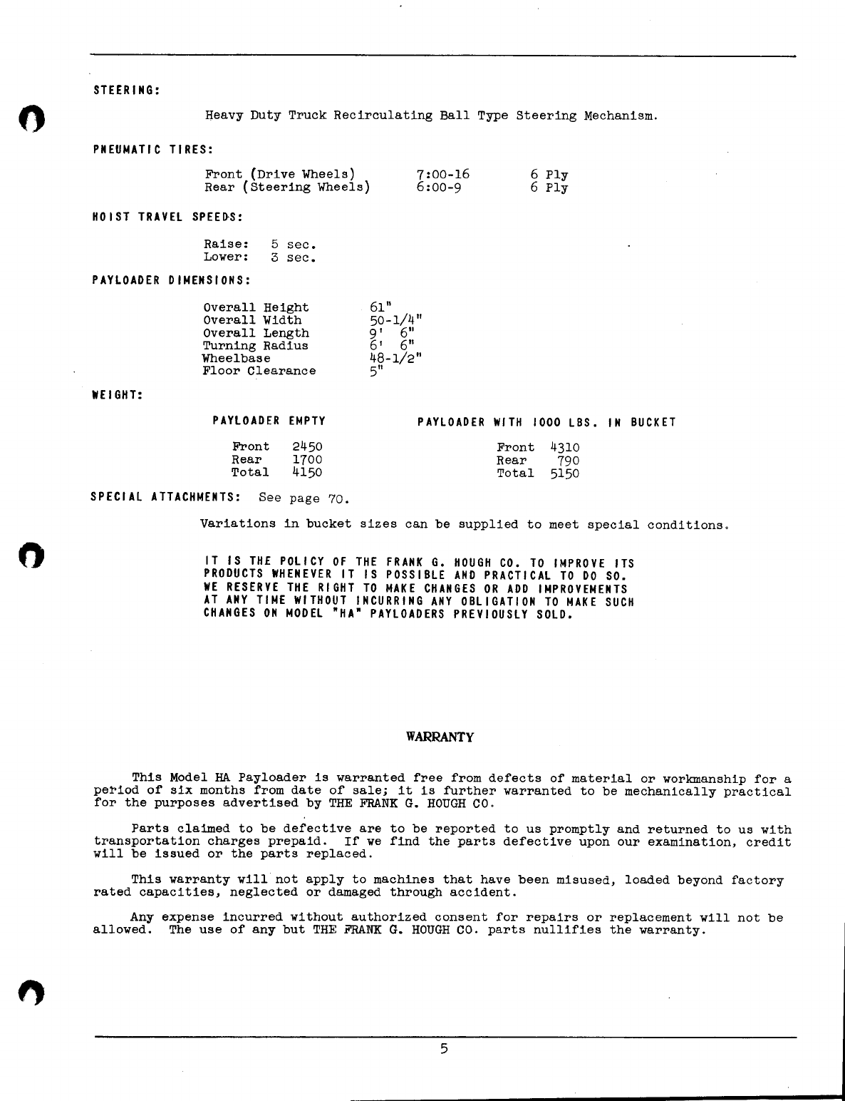
STEERING:
o
Heavy Duty Truck Recirculating Ball Type Steering Mechanism.
PNEUMATIC TIRES:
Front (Drive Wheels)
Rear (Steering Wheels)
7:00-16
6:00-9
6
Ply
6
Ply
HOIST TRAVEL SPEE~S:
Raise:
Lower: 5 sec.
3
sec.
PAYLOADER DIMENSIONS:
Overall Height
Overall Width
Overall Length
Turning Radius
Wheelbase
Floor Clearance
61"
50-1/4"
9' 6"
6' 6"
48-1/2"
5"
WEIGHT:
PAYLOADER EMPTY PAYLOADER WITH 1000 LBS. IN BUCKET
Front
Rear
Total
2450
1700
4150
Front
Rear
Total
4310
790
5150
SPECI AL ATTACHMENTS: See page 70.
Variations in bucket sizes can be supplied to meet special conditions.
IT IS THE POLICY OF THE FRANK G. HOUGH CO. TO IMPROVE ITS
PRODUCTS WHENEVER IT IS POSSIBLE AND PRACTICAL TO DO SO.
WE RESERVE THE RIGHT TO MAKE CHANGES OR ADD IMPROVEMENTS
AT ANY TIME WITHOUT INCURRING ANY OBLIGATION TO MAKE SUCH
CHANGES ON MODEL "HA" PAYLOADERS PREVIOUSLY SOLD.
WARRANTY
This Model HA Payloader is warranted free from defects of material or workmanship for a
pe~iod of six months from date of sale; it is further warranted to be mechanically practical
for the purposes advertised by THE FRANK G. HOUGH CO.
Parts claimed to be defective are to be reported to us promptly and returned to us with
transportation charges prepaid. If we find the parts defective upon our examination, credit
will be issued or the parts replaced.
5
This warranty will not apply to machines that have been misused, loaded beyond factory
rated capacities, neglected or damaged through accident.
Any expense incurred without authorized consent for repairs or replacement will not be
allowed. The use of any but THE FRANK G. HOUGH CO. parts nullifies the warranty.
"
PREPARATION OF THE PAYLOADER FOR OPERATION
o
Before operating this Payloader, even to unload, check the entire unit to make sure
nothing has become loose or damaged in transit or storage. Battery cables have been dis-
connected at the factory and the cooling system drained before shipment.
DO NOT ATTEMPT TO START THE ENGINE BEFORE THE FOLLOWING POINTS HAVE BEEN CHECKED
OR DAMAGE MAY RESULT.
1.
Check the oil level in the hydraulic system reservoir to make sure it is up to the
"full" mark on the bayonet gage. The hydraulic system pump is coupled directly to
the engine crankshaft and MUST NOT be operated without oil in the hydraulic system.
(See Page 54 or 53)•
2. Check the oil level in the engine crankcase by removing the oil dip stick from the right
hand side of the engine. (See Chart Page 73).
3. Check the oil level in the transmission to be sure it is to the height of the oil level
plug on the left side.
4. Check the oil level in the final drive. Oil level plugs of the final drive are located
on the rear side of both housing extensions.
5. Check oil in the engine air cleaner cup to be sure it contains the correct amount and
grade of oil.
6. Check the master brake cylinder to make sure it is filled with brake fluid. If not fill
with "Lockheed" hydraulic brake fluid. (See Page 36).
7.
Be sure all hoses and connections are tight to prevent hydraulic oil from leaking out
and to keep mud or water from entering the system. Water entering the system will cause
pump co~osion at high velocities. (See Page 54 or 56).
o
8. Check the tire pressures. Be sure they are up to pressures recommended. Keep the valve
caps in place and tightened securely to prevent mud, dust and moisture from damaging the
valve core. (See Page 23).
9. Fill the cooling system with clean soft water, free from alkaline; never, at any time,
run the engine without the full quantity of water in the cooling system. The radiator
is fitted with a pressure type cap which must be removed to permit draining.
Capacity of the cooling system is
3i
gallons.
10. Fill the fuel tank using a gasoline with minimum octane rating of 70-72. CapaCity of
the tank is
6i
U.S. gallons. The fuel tank is located under the front shroud and
has a shut off cock attached to the tank at the fuel line connection. (FIG. 1,
Page 7).
11. Be sure all drain cocks, drain plugs, filler openings and fuel line connections are
tight and do not leak.
12. Connect battery cables and check the dash instruments to be sure they function properly.
Check the battery to be sure the plates are covered with water. If not, add distilled
water or clean rain water. (See Page 50 or 52).
Before putting this Payloader in operation, it ·would be wise at this time to write the
serial number of Payloader, engine number and serial numbers of the transmission, final
drive, pump and valve in the space provided on the inside front cover. This is essential
data and will be required when ordering repair parts.
With the Payloader properly serviced and checked, the engine may be started.
6

"
TANK FILLER
~~+----,\-Ol L GAGE
~I-\---+--.
AM METER
TEMPERATURE
GAGE
Fig. 1
DASH INSTRUAIENTS
&
CONTROLS
STARTER
BUTTON
'I..AJJj_£
CONTROL
LEVER
CHOKE
Fig. 2
VALVE LEVER
&
STARTER BUTTON
7
OPERATING THE PAYLOADER
DRIVING THE PAYLOADER (See Fig. I and 2, page 7).
This Payloader is equipped with a two speed forward and a two speed reverse trans-
mission.
The speeds and direction desired is selected by shifting a RANGE LEVER and a DIRECTIONAL
LEVER, located on each side of the steering column.
RANGE LEVER
The
RANGE
lever is located on the right hand side of the steering column. This lever is
in
NEUTRAL
when it is in a vertical position. When pulled backward from neutral the trans-
mission has been shifted to
LOW
range. When pushed forward from neutral the transmission has
been shifted to
HIGH
range.
The low speed range is used for working conditions where more power is needed.
The high speed range is used primarily for transporting loads to various ~ocations.
DIRECTIONAL LEVER
The
DIRECTIONAL
lever is located on the left hand side of the steering column. This
lever is in
NEUTRAL
when it is in a vertical position. When pulled backward from neutral the
transmission is in
REVERSE
gear. When pushed forward from neutral the transmission has been
shifted to
FORWARD
gear.
FOOT PEDALS
The
CLUTcH
pedal is located on the LEFT side of the directional lever. When pushed down
the transmission is disengaged from the engine. Always keep the clutch pedal depressed when
shifting either the range lever or the directional lever. DO NOT engage the clutch suddenly,
'I
thus allowing the Payloader to jerk with the load. Release the pressure on this pedal slowly '-'
allowing the clutch to engage gradually.
CAUTION: DO NOT ATTEMPT TO SHIFT GEARS WHILE THE PAYLOADER IS IN MOTION.
DO NOT DRIVE THE PAYLOADER WITH THE FOOT RESTING ON THE CLUTCH PEDAL. THIS WILL
CAUSE UNDUE WEAR ON THE CLUTCH FACINGS AND THROWOUT BEARING.
The
BRAKE PEDAL
Payloader to a STOP.
clutch engaged until
pressing the brake.
lye This allows the
ings.
is located on the right side of the range lever and is used to bring the
Depress the brake firmly when braking. It is good practice to keep the
the Payloader has been slowed down and nearly brought to a halt by de-
Then disengage the clutch and stop the motion of the Payloader complete-
engine compression to assist the brake and saves wear on the brake lin-
The
ACCELERATOR
pedal is located to the right of the brake pedal. Applying pressure on
this pedal increases the flow of fuel to the cylinders by opening the carburetor intake.
This increases the engine speed thus accelerating the motion of the Payloader. Apply a
slight increasing pressure on the accelerator pedal while slowly releasing pressure on the
clutch pedal. This allows the Payloader to start evenly, without jerking. The raising and
lowering speed of the booms and bucket is also governed by the accelerator.
DASH INSTRUMENTS
IGNITI~N
SWITCH.
controls the current to the dash instruments. It is also used in start-
ing and stopping the engine.
AMMETER
indicates whether the battery is being charged or discharged. The needle should
be in the "charge" range during operation. If in "discharge" range continuously, the cause
should be investigated to avoid completely discharging the battery.
TEMPERATURE GAGE
indicates the temperature of the liquid in the cooling system. The
gage should register in the Vicinity ~f 160
0
F. for normal operation. Temperature may
indicate as high as 200
0
F. when operating in confined quarters.
GIL PRESSURE GAGE
indicates the pounds pressure of the oil circulating through the en-
gine. If this gage fails to register, .stop the engine immediately and determine the cause.
S
CHOKE ROD
is used to enrich the fuel mixture. Pull the rod out to choke.
STARTER BUTTON
completes the electrical circuit between the battery and the starting
motor. Release the pressure on this button as soon as the engine starts. Do not run the
starting motor more than
t
minute at one time.
OPERATING THE HOIST
Since the engine also operates the hydraulic pump, the hoists may be used as soon as the
engine is started.
The travel of the booms and bucket is controlled by a hydraulic valve which regulates
the flow of oil to the rams. This valve has "RAISE", "HOLD", and "LOWER" positions and is
operated by a valve control lever located on the left side of the seat support plate.
The bucket is "RAISED" by moving the valve control lever backward, toward the operator's
seat. The booms and bucket will raise in proportion to the engine speed.
The "HOLD" is the neutral or centralized position of the valve control lever. The booms
and bucket may be stopped and held in any point of travel by placing the valve control lever
in the "HOLD" position.
The bucket is "LOWERED" by moving the valve control lever forward or away from the
operator's seat.
LOADING THE BUCKET
When loading the bucket the normal operation is to drive the Payloader forward with the
bucket down. (Low gear is the best average loading speed). As the bucket fills, it should
be raised gradually. This movement, combined with the forward motion of the Paylpader will
cause an action similiar to a "dipper" stick shovel.
o
The loading operation should be done on a level or slightly uphill grade if possible.
The inherent tendency is to "dig in" when working down slope. Also, backing up-hill
with a load is difficult due to increased weight on the drive wheels.
STARTING THE ENGINE
CAUTION: NEVER ATTEMPT TO START THE ENGINE WITHOUT OIL IN THE HYDRAULIC SYSTEM.
Before starting the engine, place the RANGE lever and the DIRECTIONAL lever in the
neutral positions; and the bucket CONTROL lever in the hold position. (See fig. 1
&
fig. 2
page 7).
Be sure the gasoline shut off cock is open. (See fig. 1 page 7).
Pullout the ignition switch on the left hand side of the dash and check the ammeter to
see that it registers. (Fig. 1 page 7).
Press the starter button located on the right side of the seat plate. The choke rod is
located on the left side. (Fig. 2 page 7). If necessary pull the choke rod out slightly
to start.
Immediately on starting the engine, check the oil pressure gage to be sure it is
registering. If not, stop the engine immediately by pushing in the ignition switch, and
inspect the oil system to learn the cause of oil pressure failure.
The oil pressure gage will register between 15
&
20 Ibs. at normal operating speeds.
STOPPING THE ENGINE
To stop the engine, merely push on the ignition switch button. Be sure all levers are
in neutral position before leaving the seat.
It is advisable to close the fuel line shut-off cock if the Pay~oader is to remain idle
for any length of time.
9

----- -- --_
TRANSPORTING LOADS
For transportation of loads under average conditions it is recommended that the cutting
edge of the bucket be held about four (4) feet off the ground. Do not transport loads with
the'bucket fully raised ..
If traveling on a side slope, it is advisable to transport loads with the bucket near
the gro~d as this will give better stability.
DUMPING THE BUCKET
To "dump the bucket", pull back sharply on the bucket trip lever, located on the right
hand boom. This action "Trips" or untatches the bucket hooks and allows the bucket to pivot
forward on the hinge pins, 'dumping the load.
LATCHING THE BUCKET
To "relatch" the bucket, lower the booms and bucket while the Pay-loaderis moving in a
reverse direction. As the cutting edge touches the floor or ground, the bucket will pivot on
the hinge pins and automatically relatch.
AVO I D
Ace IDE N T S
Most aCCidents, whether they occur in industry, on
the farm, at home, or on the highway, are caused by
the failure of some individual to follow simple and
fundamental safety rules or precautions. For this
reason most accidents can be prevented by recognizing
the real cause and doing something about it before the
accident occurs.
Regardless of the care used in the design and con-
struction of any type of equipment, there are many con-
ditions that can not be completely safe guarded against
without interfering with reasonable accessibility and
efficient operation.
A CAREFUL OPERATOR IS THE BEST INSURANCE AGAINST AN
ACCIDENT.
THE COMPLETE OBSERVANCE OF ONE SIMPLE RULE WOULD PREVENT
MANY THOUSAND SERIOUS INJURIES EACH YEAR. THAT RULE IS:
"'ever attempt to clean. otl
or
adjust
a
machtne whtle tt
ts
tn motion!"
"National Safety Council"
10

ROUTINE SERVICE AND INSPECTION
The operating life of the Payloader may be considerably extended and fewer shut downs
will be experienced if the unit is properly serviced at regular intervals. Often major
repairs or shut downs can be avoided if the Payloader is inspected regularly and trouble
corrected while it is of a mirtornature.
The following outline gives points which should be lubricated and checked at each
inspection period.
For all lubrication points refer to Lubrication Chart and Lubrication Instruction on
pages 73-72-71.
TEN
(10)
HOUR SERVICE
Lubricate
Steering Axle Bell Crank
Tie Rod Ends
King Pins
Spindles
Drag Link
Radius 'Rod Pivots
Clutch Release Bearing
Valve Control Lever
Brake Pedal
Clutch Pedal
Gear Shift Levers
Boom Pivots
Guide Pivots
Ram Pivots
Latch Shaft
Latch Hooks
Check
Battery
Connections
Hydraulic Hoses
Clutch Pedal Play
Crank Case Oil Level
Cooling System Content
Air Cleaner
SIXTY (60) HOUR SERVICE
Brake
&
Clutch Pedal Play
Grease Hydraulic Pump
Check Hydraulic Oil
Flush Cooling System
Check Water Pump
Check Oil Level in Master Brake
Cylinder
Gasoline Line Filter
Tighten Nuts
&
Capscrews
Clean
&
Refill Engine Air Filter Cup
Fill Distributor Grease Cup
Clean Transmission Breather
Clean Crank Case Breather
Change Crank Case Oil
Lubricate Universal Joints
Check and Clean Hydraulic
Suction Line Strainer Drain
&
Refill Hydraulic System
Check
&
Grease Steering Gear
TWO HUNDRED
(200)
HOUR SERVICE
FOUR HUNDRED
(~OO)
HOUR SERVICE
Repack Wheels
Flush Hydraulic System
Change Transmission Oil
Change Final Drive Oil
Check Distributor
Check Wiring Connections
When operating in wet or muddy conditions be sure all connections are tight. Do not
allow moisture to enter the hydraulic system.
Never, under any circumstances, pour cold water into a hot engine. To do so may result
in cracking the cylinder head or the cylinder block.
COLD WEATHER OPERATIONS
"
When operating the pay'loaderin temperatures of 32 F. (0 C.) or lower, there is,danger
of the water freezing in the cooling system. To prevent this, use one of the anti-freeze
solutions shown on chart page 12.
11

ANTI-FREEZE SOLUTIONS
Distilled Glycerine Ethylene Glycol
Percent
by Freezing Point Specific Freezing Point Specific
Volume OoC 32
0
FGravity OoC 32
0
FGravity
0% 032 1.000 032 1.000
10% -2 29 1.029 -3 26 1.016
20% -6 21 1.057 -9 16 1.031
30% -11 12 1.085 -16 31.045
40% -18 01.112 -24 -11 1.058
50% -26 -15 1.140 -35 -31 1.D70
IMPORTANT:
Do not use alcohol as an anti-freeze as it will boil away at average temperatures.
Do not use a calcium chloride solution or any alkaline solution as they are in-
jurious to metal.
Before filling radiator in freezing weather, cover entire radiator, start engine
and put in the water immediately. This prevents the water from freezing during
the warm up period.
12
MAINTENANCE SECTION
HYDRAULIC HOIST SYSTEM
(See Page 56 or Page 54)
The hydraulic system consists of an oil reservoir, a Vickers vane type pump, a control
valve, two rams and the connecting hoses.
The pump draws oil from the reservoir thru the suction line, and forces it thru the
high pressure line into the control valve, which is manually regulated by the operator.
In "raise" position the oil is directed into the rams; in "hold" position the oil passes
thru the valve to the reservoir; in "lower" position the valve permits the rams to telescope,
so that oil from the rams flows back to the reservoir along with the oil coming from the
pump.
The pump is protected, by a pressure relief, agai~st severe overloads.
CARE OF HYDRAULIC SYSTEM
1. Check the oil level in the reservoir every ten (10) hours of operation. The level
should be to the "full" mark on the bayonet gauge or approximately 3 inches from the
top of the reservoir. The bucket should be resting on the ground when the oil level
is checked.
2. Check all hoses and connections for leaks every ten (10) hours of operation.
3. Change hydraulic oil after every two hundred (200) hours of operation.
4. A "high" reservoir oil level will result in fouled spark plugs and oil in the air pre-
cleaner bowl.
To change oil procede as follows.
~ DRAINING THE SYSTEM
ALWAYS DRAIN THE SYSTEM AFTER LOADER OPERATION, WHILE THE OIL IS STILL WARM.
1. Remove cleanout cover and filler plug from top of Reservoir.
2. Place a container large enough to hold 7 or 8 gallons directly under the drain plug
on the bottom of the reservoir and remove the drain plug.
3. Break the hose connection at the "tee" in the line between the rams to drain the high
pressure line.
4. Break the suction line hose connection at the reservoir to drain the low pressure line.
5. When the oil has drained reach into the reservoir and remove the suction line strainer
and wash in clean gasoline ~eing sure to remove all particles of dirt. A dirty strainer
will retard the oil flow and cause the pump to "howl".
6. Clean out all dirt and sludge which has collected on the bottom of the reservoir.
7. The drain plug is a magnetic type and must be cleaned thoroughly before replaclllg.
8. Flush the system every four hundred (400) hours of operation. To flush the system re-
fill the reservoir with 3 gals. of kerosene mixed with 2 gals. of lubricating oil. Run
the pump for approximately five minutes raising and lowering the bucket at an acceler-
ated speed during this period. Then shut off the engine and drain as before being sure
to disconnect the hoses.
13
9. Clean off all parts of the system, paying special attention to all connection points.
Connect all hoses, replace drain plug and hand hole cover. Refill with best grade of
SAE 10 oil.
Capacity of the hydraulic system is 6 gals approx. to the "full" mark on the
bayonet gauge, approximately 3" from the top of the reservoir.
10. After any work has been done on the hydraulic system or after changing oil, the system
must be "bled" or purged of air. This must be done before the loader is again put into
operation.
"BLEEDING" THE SYSTIM
Air in the hydraulic system will cause difficulty in controling the action of the
bucket. The booms and bucket will raise and lower with a series of jerks and the rams may
chatter. To enable the bucket to act smoothly procede as follows.
1.
Raise the booms and bucket to full height and hold them in this position.
2. Loosen the screw or plug in the upper end of the ram until air begins to escape. Moving
the valve control lever alternately between raise and hold positions will cause the air
to escape faster. Note that as the air is removed the bucket tends to lower itself thus
forcing out air by the weight of the bucket. This must be done on each ram.
3. As soon as air bubbles cease, tighten the bleeder plug securely. Raising the bucket
with the bleeder plug opened may cause more air to be drawn into the system.
4. Clean the rams of escaped oil.
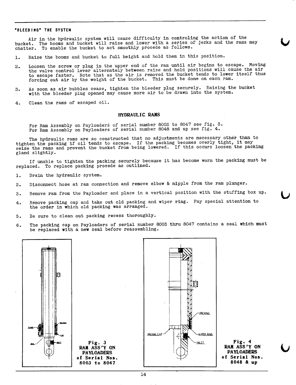
HYDRAULiC RAMS
For Ram Assembly on Payloaders of serial number 8003 to 8047 see fig. 3.
For Ram Assembly on Payloaders of serial number 8048 and up see fig. 4.
The hydraulic rams are so constructed that no adjustments are necessary other than to
tighten the packing if oil tends to escape. If the packing becomes overly tight, it may
seize the rams and prevent the bucket from being lowered. If this occurs loosen the packing
gland slightly.
If unable to tighten the packing securely because it has become worn the packing must be
replaced. To replace packing procede as outlined.
1. Drain the hydraulic system.
2. Disconnect hose at ram connection and remove elbow
&
nipple from the ram plunger.
3. Remove ram from the Payloader and place in a vertical position with the stuffing box up.
4. Remove packing cap and take out old packing and wiper ring. Pay special attention to
the order in which old packing was arranged.
5. Be sure to clean out packing recess thoroughly.
6. The packing cap on Payloaders of serial number 8003 thru 8047 contains a seal which must
be replaced with a new seal before reassembling.
Fig. 3
RAJ(
ASS'Y ON
PAYLOADERS
of Sedal Nos.
8003
to
8047
Fig. 4
RAJ(
ASS'Y ON
PAYLOADERS
of Serial Nos.
8048
&:
up
14

o
7. The leather rings and the seal of the replacement packing should be soaked in oil before
inserting in the ram. Do not soak the Neoprene rings.
8.
Insert the new packing rings in the same order and position in which the old packing had
been removed. Make sure each lip is worked down smoothly, an ice pick or similar tool
may be used for this purpose. Do not use cut or distorted rings.
9. With'the new packing inserted properly, there should be 1/16" to 3/32" compression when
the packing cap is tightened.
10. Pull the packing cap down tightly. There is no other adjustment necessary other than
retightening the packing cap after the packing rings become worn.
CONTROLVALVE
The function of the control valve is to control the .direction of oil flow to raise and
lower the bucket and to enable the operator to stop and hold the bucket at any point of
travel.
This paragraph pertains to valves used on Payloader of Serial numbers 8003 thru 8047.
It is imperative that the operator and mechanic know the position of the poppets if the
system fails to operate due to the valve.
With the valve control lever in "RAISE" position the poppets in both valve chambers must
seat solidly. See fig. 5.
In observing fig. 5 note the high pressure poppet is open due to pressure from the pump
and is free of the cam shaft.
Fig. 5
POPPETS IN "RAISE" POSITION Fig. 6
POPPETS IN "HOLD" POSITION
~I
Fig. 7
POPPETS IN "LOWER" POSITION
If the poppets do not seat solidly, remove them from the.valve body and grind just
enough stOC$ from the lower ends of the poppets so they will not rest on the cam shaft with
the valve in "Raise" position. The poppets, both inner and outer, must then be "Lapped" in
with regular automotive valve grinding compound, in order to provide a good seat.
NOTE: IF THE ABOVE PROCEDURE IS NECESSARY, WASH AND CLEAN VALVE THOROUGHLY BEFORE OPERATING
HYDRAULIC SYSTEM.
With the Valve Control Lever in "Hold" position the high pressure poppet should be
closed and the low.pressure poppet should be open. (See fig. 6).
With the Valve Control Lever in "Lower" position, both the high and low pressure poppets
should be open. (See fig. 7).
15

HYDRAULIC CONTROL VALVE
(Payloader Serial Nos. 8048
&
up)
The type valve used on these machines
is a "Hydreco spool valve". (See fig. 8).
There are no adjustments to be made
on this valve. It is advisable to remove
valve from Payloader, disassemble, wash
and clean thoroughly every 400 hours of
operation. Use parts drawing on page 61
to identify and locate the various parts
of this unit.
Fig. 8
VALVE ASS'Y PAYLOADERS
of Serial Numbers
8048
&
up
HYDRAULI C PUMP
This pump is a "Vickers" Rotary vane type, assembled for left hand operation, and has no
volume adjustment.
An
arrow stamped on the body indicates direction of rotation. The pump
must be lubricated every sixty (60) hours of operation with a high temperature sodium soap
type grease. There is a grease fitting provided for this on the upper side of the pump
body. (See page 58).
Shaft packing of the pump is not subject to pressure and normally does not require
replacement.
Vanes, being subject to centrifugal force and fluid pressure, automatically compensate
for.any normal year.
DISMANTLING AND. REASSEMBLING PUMP
Inspection of the pumping
cartridge parts in the vane type
single pump can be made as
follows:
The pumping cartridge consist of
a rotor "E", vanes "F" valve plate
bushings "D" and "H", and cam ring
"G". All moving parts, except shaft
and shaft bearings, operate within
this cartridge assembly. No moving
parts therefore are in contact with
the body "T".
Remove the.head screws "A" and
the head "B". The head end valve
plate bushing "D" can then be pulled
out, leaving exposed the rotor "E",
vanes "F" and the cam ring "G".
,..--------T-BO DY
• fiTTING
>:":"\"r-~----v-SCREW
H-BUSHING
~~~~H!~iE~iiiiiiiif~-KEY
Q-BEARING
A-SCREW
C -PACKING
B- HEAD- __
..J
- PIN
Fig. 9
PUMP ASSEMBLY - SIDE VIEW
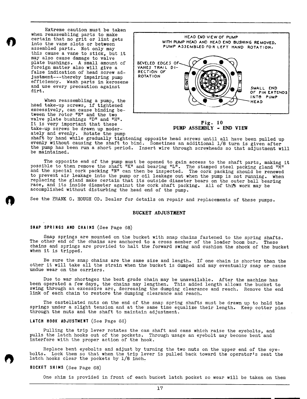
Be parti~ularly careful to note the position of the rotor and vanes, also the position
of the ring pin "P". These parts may all be reassembled incorrectly if not carefully
checked, because of the fact that provision is made in the design for either right-hand or
left-hand assembly. The position of cam ring "G" should also be noted carefully.
These parts can all be removed for inspection, and the shaft-end valve plate bushing
"H" will then be exposed. It too can be removed by a hook-shaped tool. Parts that show
damage or excess wear should be replaced. The vanes can be turned end-for-end so that the
inside edge is now against·the cam ring-----thus renewing the vanes for future service.
Worn edges must be stoned so vanes move freely in rotor slots and beveled edges must trail
direction of rotation.
Reassemble in reverse order with parts replaced in original pOSitions, using parts
drawing as a supplementary guide. Renew head ring packing
"c"
if it has become compressed
or damaged, otherwise air will be drawn in when the pump is running or oil will leak out
when not running. Assemble the pump head so that ring hole registers with protruding part
of ring pin "P".
16
When reassembling a pump, the
head take-up screws, if tightened
excessively, can cause binding be-
tween the rotor "E" and the two
valve plate bushings "D" and "H".
It is very important that these
take-up screws be drawn up moder-
ately and evenly. Rotate the pump
shaft by hand while gradually tightening opposite head screws until all have been pulled up
evenly without causing the shaft to bind. Sometines an additional 1/8 turn is given after
the pump has been run a short period. Insert wire through screwheads so that adjustment will
be maintained.
Extreme caution must be taken
when reassembling parts to make
certain that no grit or lint gets
into the vane slots or between
assembled parts. Not only may
this cause a vane to stick, but it
may also cause damage to valve
plate bushings. A small amount of
foreign matter also will give a
false indication of head screw ad-
justment---thereby impairing pump
efficiency. Wash parts in kerosene
and use every precaution against
dirt.
HEAD E~D VIEW OF PUMP
WITH PUMP Hf:AD AND HEAD END BUSHING REMOVED.
PUMP ASSEMBLED FOR LEFT HAND ROTATION.
BEVELED EDC.E~ OF
YANES TRAI L DI-
RECTION OF
ROTATION
SMALL END
OF PIN EXTENDS
INT~
PUMP
HEAD
Fig
0
10
PUMP ASSEMBLY - END VIEW
The opposite end of the pump must be opened to gain access to the shaft parts, making it
possible to then remove the shaft "K" and bearing "L". The stamped steel packing gland "M"
and the special cork packing "N" can then be inspected. The cork packing should be renewed
to prevent air leakage into the pump or oil leakage out when the pump is not running. When
replacing the gland make certain that its outside diameter bears on the outer ball bearing
race, and its inside diameter against the cork shaft packing. All of thi~ work may be
accomplished without disturbing the head end of the pump.
See the
ERANK
G. HOUGH CO. Dealer for details on repair and replacements of these pumps.
SNAP SPRINGS AND CHAINS
(See Page 68)
BUCKET ADJUSTMENT
Snap springs are mounted on the bucket with snap chains fastened to the spring shafts.
The other end of the chains are anchored to a cross member of the loader boom bar. These
chains and springs are provided to halt the forward swing and cushion the shock of the bucket
when it is tripped.
Be sure the snap chains are the same size and length. If one chain is shorter than the
other it will take all the strain when the bucket is dumped and may eventually snap or cause
undue wear on the carriers.
Due to war shortages the best grade chain may be unavailable. After the machine has
been operated a few days, the chains may lengthen. This added length allows the bucket to
swing through an excessive arc, decreaSing the dumping clearance and reach. Remove the end
link of each chain to restore the dumping clearance and reach.
The castellated nuts on the end of the snap spring shafts must be drawn up to hold the
springs under a slight tension and at the same time equalize their length. Keep cotter pins
through the nuts and the shaft to maintain adjustment.
LATCH HOOK ADJUSTMENT
(See Page 66)
Pulling the trip lever rotates the cam shaft and cams which raise the eyebolts, and
pulls the latch hooks out of the pockets. Through usage an eyebolt may become bent and
interfere with the proper action of the hook.
Replace bent eyebolts and adjust by turning the two nuts on the upper end of the eye-
bolts. Lock them so that when the trip lever is pulled back toward the operator's seat the
latch hooks clear the pockets by 1/8 inch.
BUCKET SHIMS
(See Page 68)
One shim is provided in front of each bucket latch pocket so wear will be taken on them
17

and not on the pockets. When the upper edges of the shims become worn they should be in-
verted or turned end for end, thus keeping a square edge in contact with the latch hook. If
this is not done the bucket will not latch properly.
ENCiINE
See CONDENSED Specifications
&
Service Data page 4.
Payloaders, serial no's 8003 thru 8047 have a Waukesha FC157C engine equipped with
Magneto ignition system. See page 27.
Payloaders, serial no's 8048
&
up have a Waukesha FC157D engine equipped with
Distributo~ ignition system. See page 30.
A Waukesha FC engine Parts and Instruction manual is inserted in the envelope located on
the·inside rear cover of this manual.
FUEL SYSTEM:
The fuel system of this Payloader is a gravity feed type with the fuel strainer located
on the left side of the engine.
A fuel pump may be 'used on the Payloader which must be a special A-C Spark Plug fuel
pump #1538791 and can only be serviced by the FRANK G. HOUGH CO. Dealers or any United Motors
service station.
FAN BELT
REMOVING
&
REPLACING
1. Shut off engine and lower bucket to the floor.
2. Remove hood sides from Payloader.
3. Remove hose clip which attaches to governor on the left hand side of the engine.
4. Remove inspection cover from rear grille casting.
5. Remove the 6 capscrews holding pump drive flange to engine fan belt pulley.
o.
Remove four bolts which hold pump to pump mounting bracket.
7. Pull the pump out toward rear of machine as far as it will go.
8. Loosen the generator bracket adjusting nut and push generator in toward the engine and
tighten nut.
9. Remove fan belt from generator pulley and lower fan belt pulley; then slip belt over the
fan to remove from the machine.
NOTE: THE ABOVE OPERATION MAY BE DONE WITHOUT REMOVING THE RADIATOR GRILLE CASTING.
ADJUSTING FAN BELT
Install the new fan belt by reversing the procedure above. With the fan belt on all
three pulleys reset the generator so that the belt can be pushed inward approximately 3/4" to
1". This is the proper tension of the belt when the generator bolts have been tightened.
18
Table of contents


