2) Make sure you alternate starting with a Small Hog Leg®
Extension (2-3/8” OD) or a Large Hog Leg® Extension
(2-7/8” OD) at every other brace. This will keep the amount of
Extensions used equal, maximizing the amount of braces you
will get from each Hog Leg® Wall Brace Kit.
3) Continue adding Hog Leg® Extensions as shown in Detail B
until the desired length is obtained. To locate where to pour
the deadman for the base of the Hog Leg®, take the height
of the brace installation and multiply by 0.75. Example:
Brace Height of 16 feet x 0.75 = Brace Run of 12 feet from
the wall.
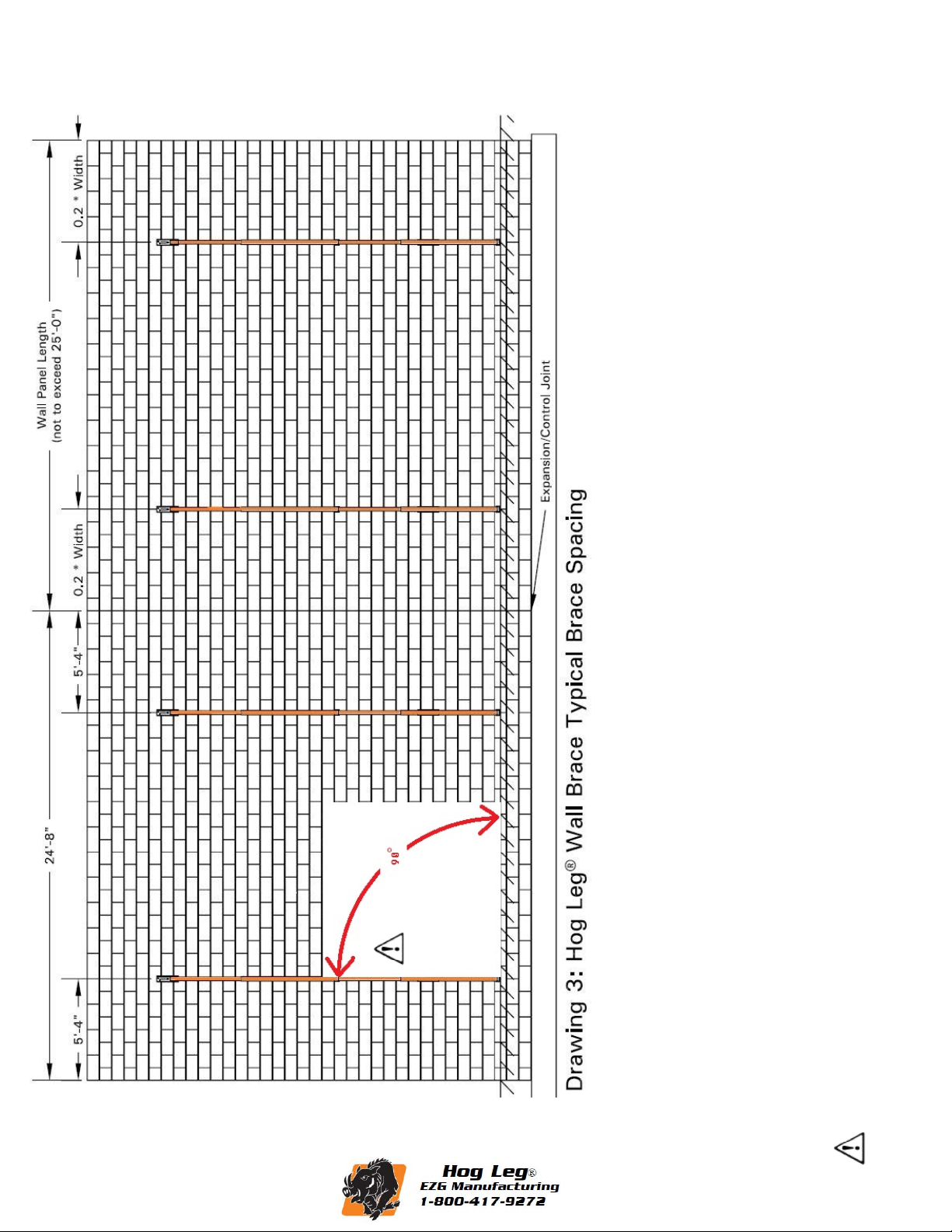
CAUTION: Keep installation as close to the design
guidelines shown in this manual as possible. If the brace
is installed at a steeper angle or beyond 90° perpendicular
to the wall, the holding power of the brace will be
reduced.
4) Secure the Floor Bracket with anchors that meet all
applicable standards and regulations as shown in Detail C.
Kicker Installation: For extreme wind speeds (greater th 40
MPH) or requirements that exceed Standard Practice for
Bracing Masonry Walls Under Construction a kicker is
required , on brace lengths 22’-11” or longer. For Brace
Lengths longer than 26’-3” a Kicker is required for all
circumstances. For extreme wind speeds (greater than 40
MPH) or requirements that exceed Standard Practice for
Bracing Masonry Walls Under Construction a Kicker and
Guide Wires are required, on brace lengths 26’-3”. For Brace
Lengths longer than 30’-5” a Kicker and Guide Wires are
required for all circumstances. The Kicker should be installed
at the midpoint of the Hog Leg® Wall Brace. The Kicker
then extends downward at a 90° angle from the Hog Leg®
Wall Brace and mounts to the wall. To determine wall height
to install kicker, refer to page 10 of this manual. For Guide
Wire installation, refer to page 11 of this manual.
1) Install the Kicker Adjustment Pipe to the Hog Leg® by
inserting the Hitch Pin through the Hog Leg® Extension
and insert Safety Clip as shown in Detail D.
2) Add Hog Leg® Extensions as required to reach the
Wall Bracket.
Removal of Hog Leg® Bracing
To comply with Standard Practice for Bracing Masonry
Walls Under Construction, the Hog Leg® Bracing System
must not be removed until the wall is permanently supported.
You may refer to this standard in Chapter 3 Section 3.5 of
the Standard Practice for Bracing Masonry Walls Under
Construction manual.
WARNING!
!
Warning: Minimum of 10” of overlap required
on Hog Leg® Extension connection.
Falling Walls, Braces, or
Components can cause
severe injury or death
Moving or relieving this brace may
cause serious injury or death. Consult
the Structural Engineer before
attempting to remove or relieve this
brace or any component. Do not
remove brace until all structural
connections are in place. Refer to
Standard Practice for Bracing
Masonry Walls Under Construction.
DANGER!
!
©Copyright 2014
www.ezgmfg.com