The Great Arnoldi JIC-911T User manual

JUST IN CASE
911 Emergency Phone
Owner’s Guide
AVOID INJURY and DAMAGE. You MUST read and
understand the instructions in this guide.
DRAFT

JUST IN CASE
Table of Contents
OVERVIEW
Contents of Core System.......................................1
INSTALLATION
Installing the Batteries............................................
Locating the Base Unit.......................................
Power Connections................................................
Telephone Line Connection................................
Connecting with DSL
OPERATION
Operating the Handset
Operating the Base Unit
Operating Range
Battery Check
System Check
Using the 911 Button
Water Resistance
PERIODIC TESTING
Replacing the Batteries
Testing Procedures
DRAFT

JUST IN CASE
Table of Contents
MAINTENANCE
TROUBLESHOOTING GUIDE
WARRANTY
REPLACEMENT PARTS
DRAFT
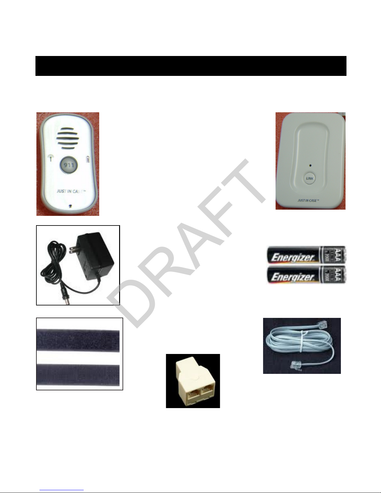
CONTENTS OF THE CORE SYSTEM
The following components are included with your JUST
IN CASE Core System:
DRAFT

This section describes the safety precautions that should be
followed during installation, use, and maintenance and care
of your JUST IN CASE phone. Read and understand the Safety
Precautions and the Owner’s Guide before using your JUST IN CASE
911 Emergency Phone. Failure to follow these safety precautions
and the instructions in this Owner’s Guide can lead to the phone
becoming inoperable and not working during an emergency.
SAFETY PRECAUTIONS
DRAFT

INSTALLATION
This section will provide you with information about the installation
of your JUST IN CASE 911 Emergency Phone Core System. The
initial set-up of your system is important in providing safe and
reliable operation.
Take the following safety precautions to prevent injuries and
damage to your Handset caused by improper handling and
installation of the batteries:
• Use ONLY specified AAA batteries.
• ALWAYS follow the installation instructions carefully.
• ALWAYS insert the batteries correctly by matching the + and
- polarity markings on the battery and the label inside the
battery compartment.
• ALWAYS remove batteries if Handset is not going to be used
for a long period of time.
• DO NOT mix old batteries with new batteries or batteries of
different types.
• DO NOT short circuit the supply terminals.
• DO NOT use rechargeable batteries.
IMPORTANT SAFETY INFORMATION
2.1 INSTALLING THE BATTERIES
DRAFT
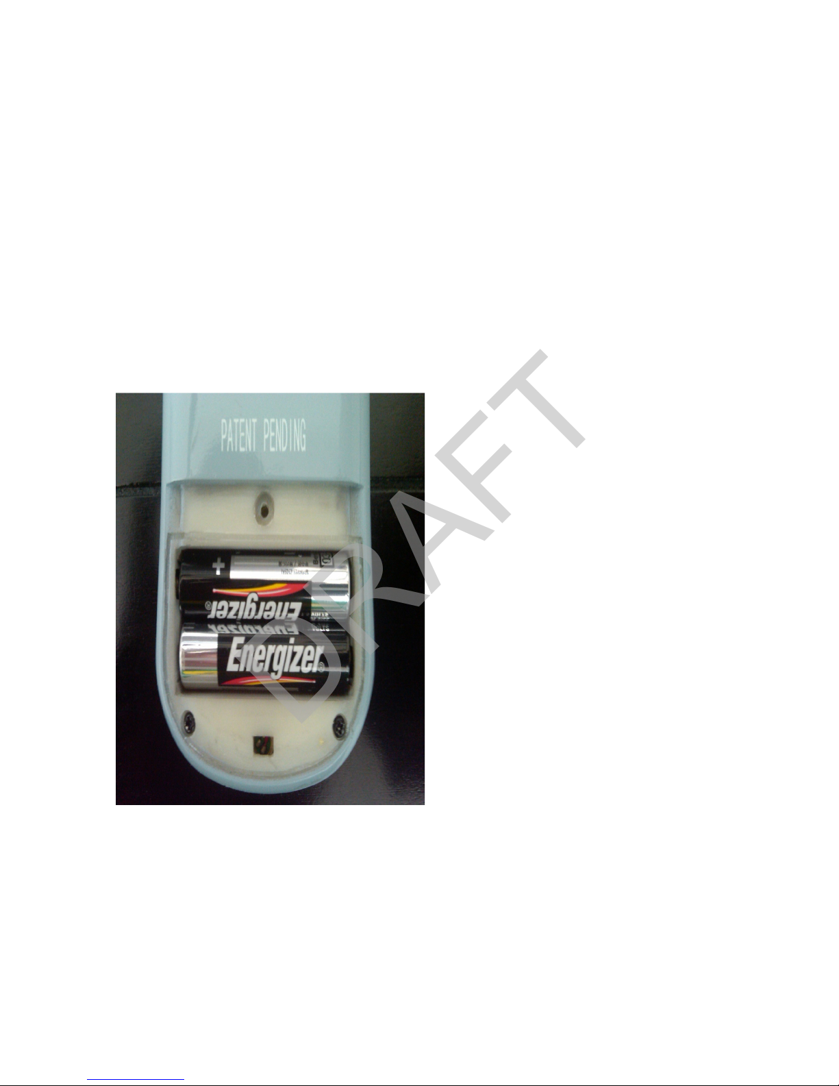
BATTERY INSTALLATION PROCEDURES:
1. Use a Phillips head screwdriver to loosen the screws in the
battery compartment door on the back of the Handset.
2. Insert two 1.5v “AAA” size batteries inside the battery
compartment as shown below (Figure 1).
3. Follow the “+/-” signs on the label inside the battery
compartment for proper installation.
4. Replace the battery compartment door and tighten the screws.
Figure 1. Correct battery placement in battery compartment on the
Handset.
DRAFT

For best results and maximum range, locate the Base Unit:
The Base Unit IS NOT WATER RESISTANT. DO NOT locate
the Base Unit near any sources of water, such as the bath
room or kitchen sink.
• In a central location in your home near a modular phone jack
and an electrical power outlet.
• AWAY from household appliances which could present electri-
cal interference. These include microwave ovens, televisions,
electric mixers or blenders, hair dryers, WiFi routers or other
cordless phones.
• DO NOT place the Base Unit on a metallic surface.
2.2 Locating the Base Unit
DRAFT

DO NOT plug the AC Power Adapter into an outlet which is
controlled by a switch. The switch could accidently be turned
off, causing the Base Unit to become inoperable.
1. Plug the AC Adapter included with your Core System into an
electrical outlet.
2. Plug the other end of the AC Adapter into the Base Unit (See
Figure 2).
3. When you have successfully connected your Base Unit to a
power source, the green POWER LED light on the Base Unit
will illuminate.
Use only the AC Adapter supplied with this product.
Use of a different adapter may cause damage to your
Base Unit and render it inoperable.
2.3 Connecting the AC Adapter
DRAFT

You do not need a special phone line to use your JUST IN CASE 911
Emergency Phone. This phone will work with your existing tele-
phone line and phone service. It works the same way as a regular
cordless phone.
Standard Telephone Connection:
1. Plug one end of the supplied telephone cord into your tele-
phone jack in the wall.
2. Plug the other end of the telephone cord into the telephone
jack on the Base Unit (See Figure 2).
NOTE: You will feel and hear a ‘click’ when the jacks are firmly
seated in the wall and the Base Unit.
Electrical Outlet Telephone Wall Jack
DRAFT
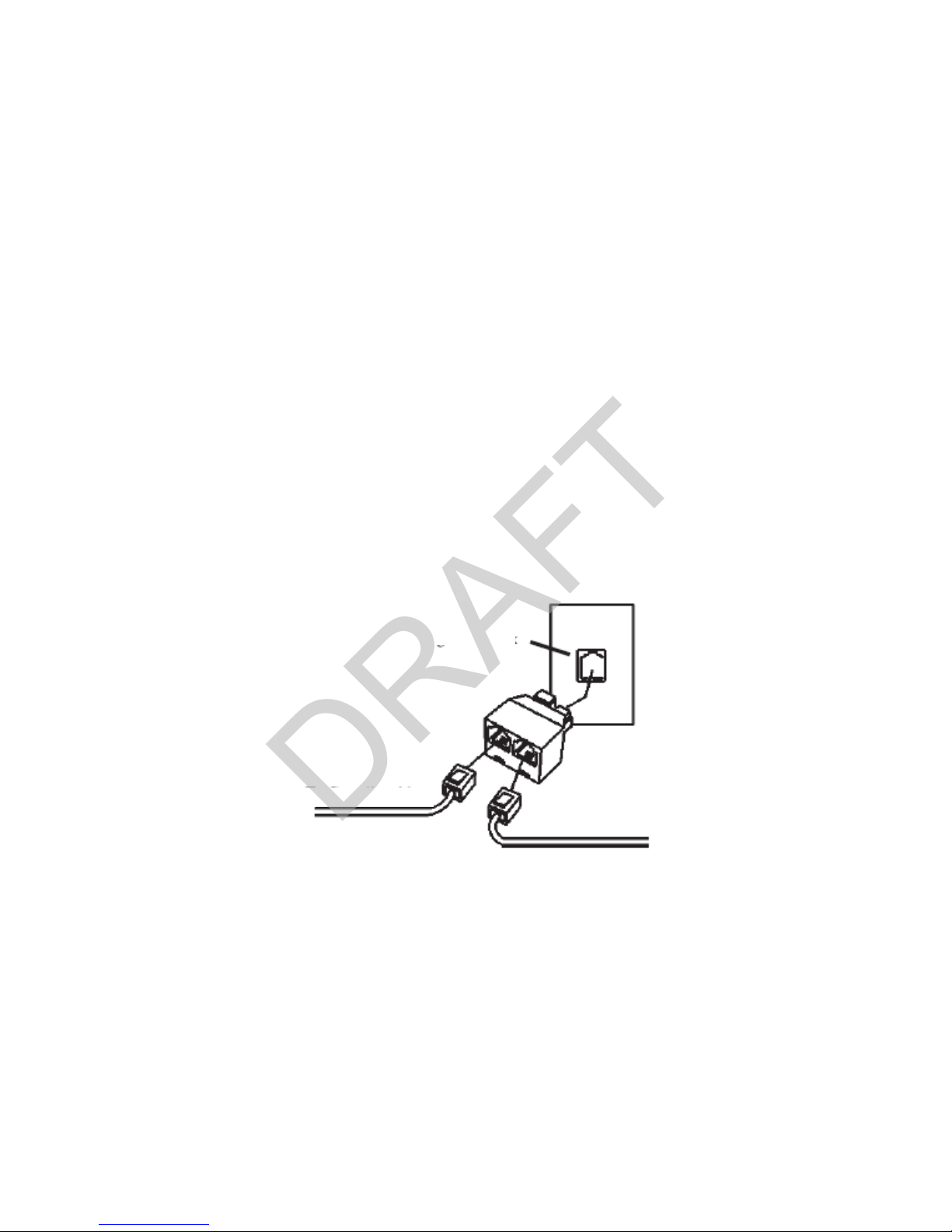
Connecting a Second Telephone:
If you need to plug in a conventional telephone into the same tele-
phone wall jack as your JUST IN CASE Base Unit:
1. Disconnect your existing telephone cord from the telelphone
jack in the wall.
2. Plug the supplied telephone line splitter into the telephone jack
in the wall ( See Figure 3).
3. Plug one end of the supplied telephone cord into the splitter.
4. Plug the other end of the telephone cord into the jack on the
back of the Base Unit.
5. Plug the telephone cord from your existing phone into the tele-
phone line splitter.
TO BASE UNIT
TO SECOND PHONE
EXISTING PHONE JACK
Figure 3. Connecting to a second phone.
DRAFT
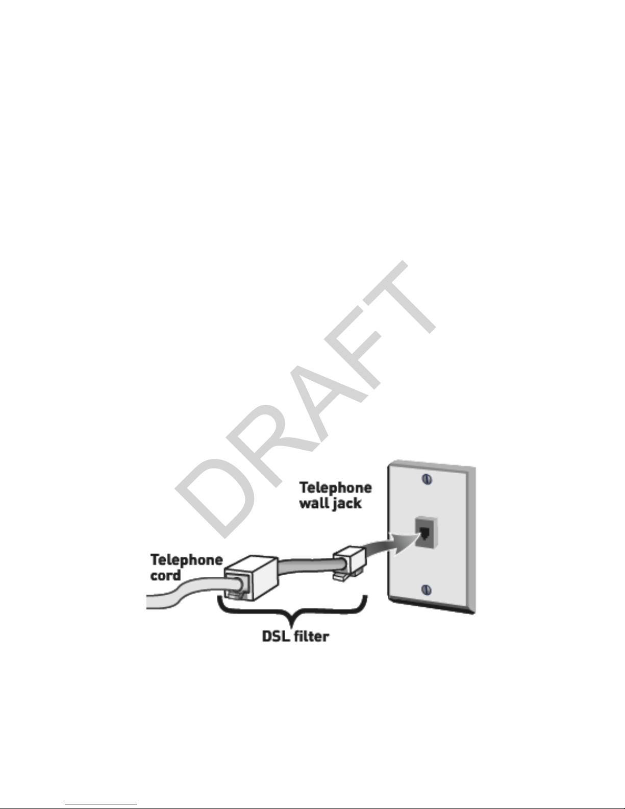
Connecting with DSL:
If your home has DSL service for your computer, follow these in-
structions for proper installation of your JUST IN CASE phone:
1. You must use a DSL filter in line with your JUST IN CASE phone
OR IT WILL NOT WORK.
2. You can obtain a DSL filter from your DSL service provider or
from an electronics store.
3. Plug the DSL filter into the telephone wall jack.
4. Plug one end of the supplied telephone cord into the jack on
the DSL filter.
5. Plug the other end of the telephone cord into the jack on the
back of the Base Unit (See Figure 4).
6. Plug the telephone cord from your existing phone into the tele-
phone line splitter.
TO BASE UNIT
Figure 4. Connecting with a DSL filter.
DRAFT
OPERATION and TESTING
This section will provide you with information about the operation
of Handset, Base Unit, and testing procedures.
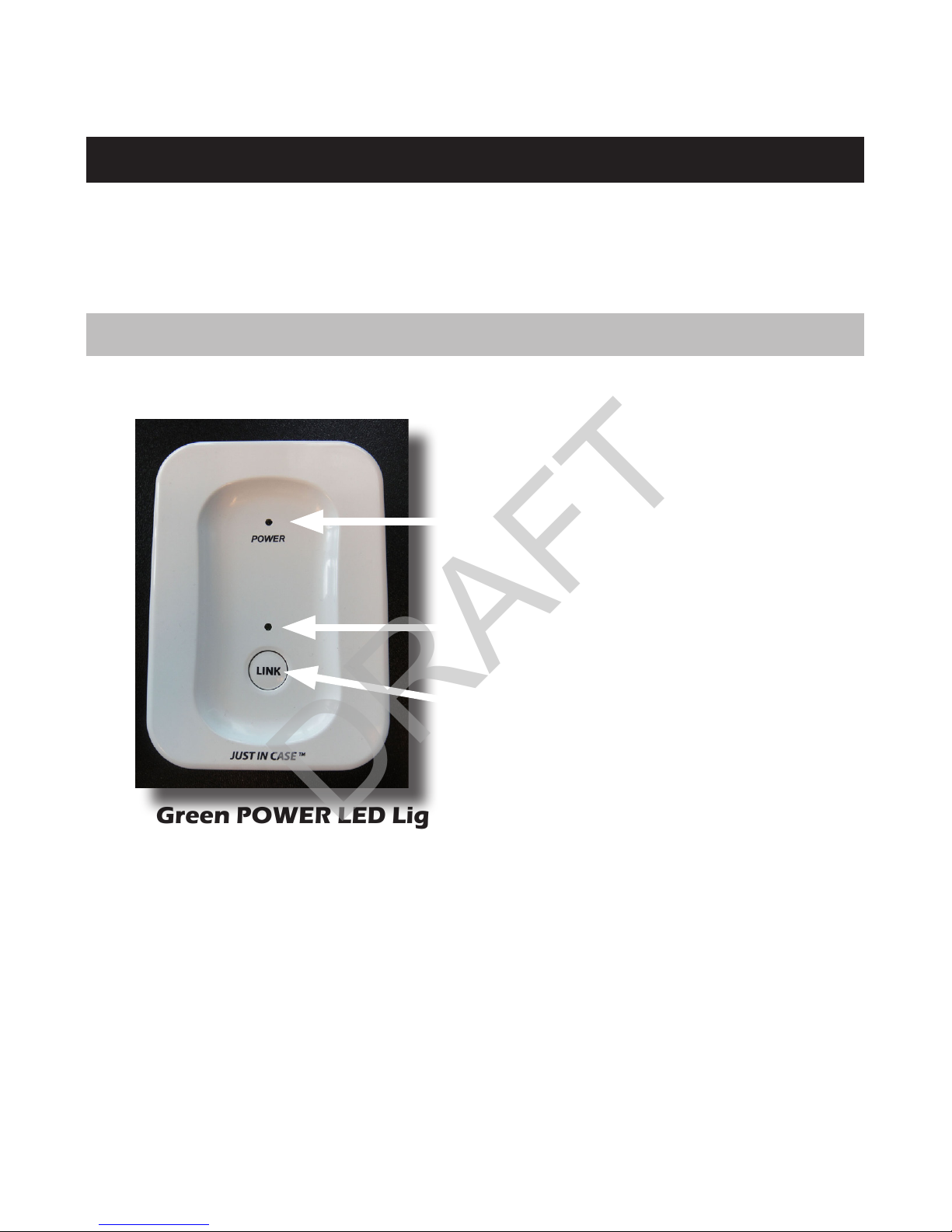
OPERATING THE BASE UNIT
Base Unit Features:
Green POWER LED Light
LINK Button
Green LINK LED Light
1. Green POWER LED Light: A solid green light indicates a
successful connection to a power source. When the LED is
off, it indicates that there is no power to the Base Unit.
2. Green LINK LED Light: A blinking green light indicates
that an additional Handset has been successfully Linked to
the Base Unit.
3. LINK Button: Press and hold for two seconds to LINK an
additional Handset to the Base Unit.
DRAFT
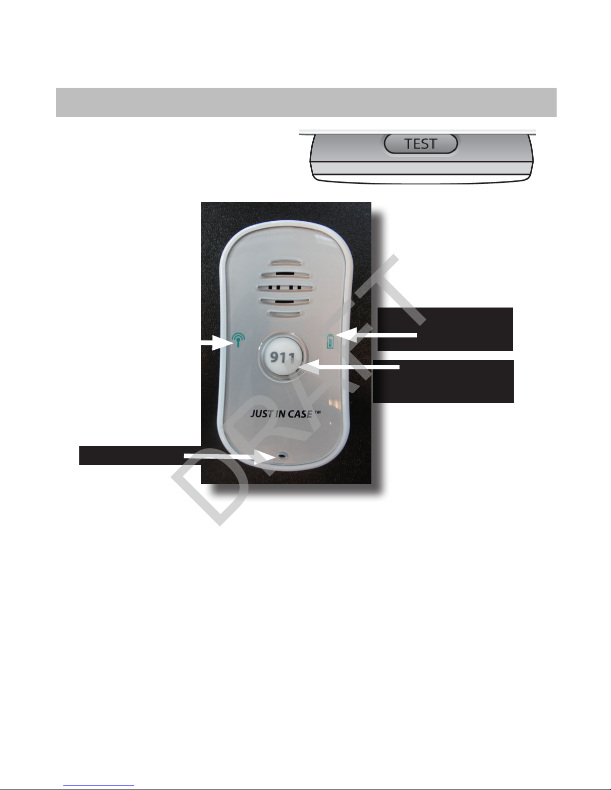
OPERATING THE HANDSET
Handset Features:
Battery LED
Light
Microphone
911 Activation
Button
System LED
Light
Speaker
TEST Button
1. TEST Button: Pressing and holding the TEST Button will
initiate the battery and system tests (See pg. 16).
2. System LED Light: This light indicates whether the Handset
is within range of the Base Unit.
3. Battery LED Light: This light indicates how much battery
life is remaining in the Handset.
4. 911 Activation Button: When you press the 911 Activation
Button, the JUST IN CASE phone will dial 911.
DRAFT

BATTERY & SYSTEM TEST PROCEDURES
This section will provide you with information about the testing
procedures for your Handset and Base Unit.
BATTERY TEST
You MUST test the batteries in your Handset TWICE a month.
Failure to test the batteries may result in your HANDSET
becoming inoperable leading to SERIOUS INJURY or DEATH.
1. Initiate the Battery and System Tests:
• A solid green light indicates that one month or more of
battery life remains.
• A blinking green light indicates that less than one month of
battery life remains. You will hear the following message:
“Please replace the batteries.”
• If the battery light does not illuminate, the batteries are
dead. You MUST replace them immediately.
• Press and release the TEST Button on the top of the
Handset.
• After you release the TEST Button, the Handset will initiate
the battery and system tests.
• NOTE: It will take approximately 2 seconds for the tests to
begin. DO NOT press the TEST Button again.
2. Battery LED Light:
WARNING
DRAFT

Warning:
AnyChangesormodificationsnotexpresslyapprovedbythepartyresponsibleforcompliance couldvoidtheuser'sauthoritytooperatetheequipment.
Thisdevice complieswithpart15oftheFCCRules. Operationissubjecttothefollowing twoconditions:(1)Thisdevice maynotcauseharmfulinterference,
and(2)thisdevicemustacceptanyinterference received,including interference thatmaycauseundesiredoperation.
IMPORTANTNOTE:
FCC RadiationExposure Statement:
ThisequipmentcomplieswithFCCradiationexposurelimitssetforthforanuncontrolledenvironment.Thisequipmentshouldbeinstalledand
operatedwithminimumdistance20cmbetweentheradiator&yourbody.
Note:ThisequipmenthasbeentestedandfoundtocomplywiththelimitsforaClass Bdigitaldevice, pursuanttopart15 oftheFCC Rules. Theselimitsare
designedtoprovidereasonableprotectionagainstharmfulinterference inaresidentialinstallation. Thisequipmentgenerates, usesandcanradiateradio
frequencyenergyand,ifnotinstalledandusedinaccordance withtheinstructions,maycauseharmfulinterference toradiocommunications. However,thereis
noguarantee thatinterference willnotoccurinaparticularinstallation. Ifthisequipmentdoescauseharmfulinterference toradioortelevisionreception, which
canbedeterminedbyturning theequipmentoffand on,theuserisencouragedtotrytocorrecttheinterference byoneormoreofthefollowing measures:
Reorientorrelocatethereceiving antenna.
Increasetheseparationbetweentheequipmentandreceiver.
Connecttheequipmentintoanoutletonacircuitdifferentfromthattowhichthereceiverisconnected.
Consultthedealeroranexperiencedradio/TVtechnicianforhelp.
Privacy of communications may not be ensured when using this phone.
Popular Emergency Phone manuals by other brands

Bell System
Bell System Master 200Plus Operator's manual

Paso
Paso PA8506-V Instructions for use

Viking
Viking BLK-3-EWP Technical practice

Assistive Technology Services
Assistive Technology Services Help Dialer 700 troubleshooting guide

Tunstall
Tunstall Lifeline 4000 user guide

N Chinastar
N Chinastar iHelp User guid

BELGACOM
BELGACOM Twistiny user manual

King Pigeon Communcation
King Pigeon Communcation T2 user manual

Viking
Viking E-1600A-BLT-EWP product manual

LogicMark
LogicMark Freedom Alert 35911 Installation & operation instructions

Rath
Rath 2100-PL9 900 MHz 12v Pedestal Installation & operation manual

Viking
Viking E-1600-02A Application note


