Guardian Telecom HDE-VoIP Series Owner's manual

Heavy Duty Emergency VoIP Telephones
HDE-VoIP Series
Installation and Operation
HDE11-VoIP HDE1100-VoIP
HDE12-VoIP HDE1200-VoIP
P007310 Rev. D 190116 1/18/2019 11:36 AM

Guardian Telecom Installation and Operation
HDE-VoIP Series Telephones
Page 2
HDE-VoIP Installation Guide P007310 Rev. E
COPYRIGHT NOTICE:
© 2019, Guardian Telecom, ALL RIGHTS RESERVED.
This manual and the related materials are the copyrighted property of Guardian Telecom
No part of this manual or related materials may be reproduced or transmitted, in any form
or by any means (except for internal use by licensed customers), without prior express
written permission of Guardian Telecom. This manual, and the products, software,
firmware, and/or hardware described in this manual are the property of Guardian Telecom,
provided under the terms of an agreement between Guardian Telecom and recipient of
this manual, and their use is subject to that agreement and its terms.
DISCLAIMER: Except as expressly and specifically stated in a written agreement
executed by Guardian Telecom, Guardian Telecom makes no representation or warranty,
express or implied, including any warranty or merchantability or fitness for any purpose,
with respect to this manual or the products, software, firmware, and/or hardware described
herein, and Guardian Telecom assumes no liability for damages or claims resulting from
any use of this manual or such products, software, firmware, and/or hardware. Guardian
Telecom reserves the right to make changes, without notice, to this manual and to any
such product, software, firmware, and/or hardware.
OPEN SOURCE STATEMENT: Certain software components included in Guardian
products are subject to the GNU General Public License (GPL) and Lesser GNU General
Public License (LGPL) “open source” or “free software” licenses. Some of this Open
Source Software may be owned by third parties. Open Source Software is not subject to
the terms and conditions of the Guardian COPYRIGHT NOTICE or software licenses.
Your right to copy, modify, and distribute any Open Source Software is determined by the
terms of the GPL, LGPL, or third party, according to who licenses that software.
Software or firmware provided by Guardian that is unrelated to Open Source Software is
copyrighted by Guardian, subject to the terms of Guardian licenses, and may not be
copied, modified, reverse-engineered, or otherwise altered without explicit written
permission from Guardian Telecom
TRADEMARK NOTICE: Guardian Telecom and the Guardian Telecom logos are
trademarks of Guardian Telecom Other product names, trademarks, and service marks
may be the trademarks or registered trademarks of their respective owners.
Toll-free 1-800-363-8010
Phone (403) 258-3100
Fax. (403) 253-4967
www.guardiantelecom.com
E-mail: [email protected]

Guardian Telecom Installation and Operation
HDE-VoIP Series Telephones
Page 3
Important Safety Instructions
1. Read these instructions.
2. Keep these instructions.
3. Heed all warnings.
4. Follow all instructions.
5. Install in accordance with the manufacturer’s instructions.
6. Do not install near any heat sources such as radiators, heat registers, stoves, or other
apparatus (including amplifiers) that produce heat.
7. Only use attachments/accessories specified by the manufacturer.
8. Refer all servicing to qualified service personnel.
9. Prior to installation, consult local building and electrical code requirements.

Guardian Telecom Installation and Operation
HDE-VoIP Series Telephones
Page 4
Table of Contents
1. Package Contents......................................................................................................5
2. Models........................................................................................................................5
3. Accessories................................................................................................................5
4. Updating Your VoIP Product ......................................................................................5
5. Product Overview.......................................................................................................6
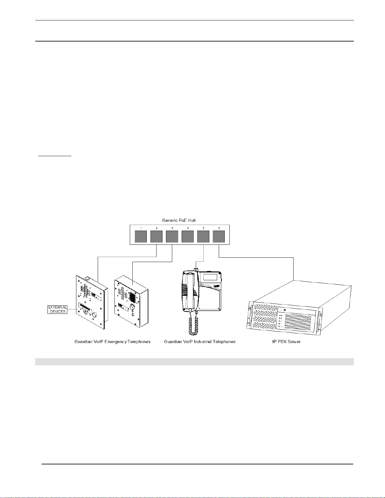
6. Typical System Installation.........................................................................................6
7. Features.....................................................................................................................7
8. Installing the HDE-11/1100-VoIP Telephones..........................................................10
9. Installing the HDE-12/1200-VoIP Telephones..........................................................13
10. Supported Protocols.................................................................................................15
11. Supported SIP Servers.............................................................................................15
12. HDE-VoIP Telephones Wiring..................................................................................15
12.1. Connections..................................................................................................15
12.2. Connecting a Device to the Auxiliary Relay..................................................16
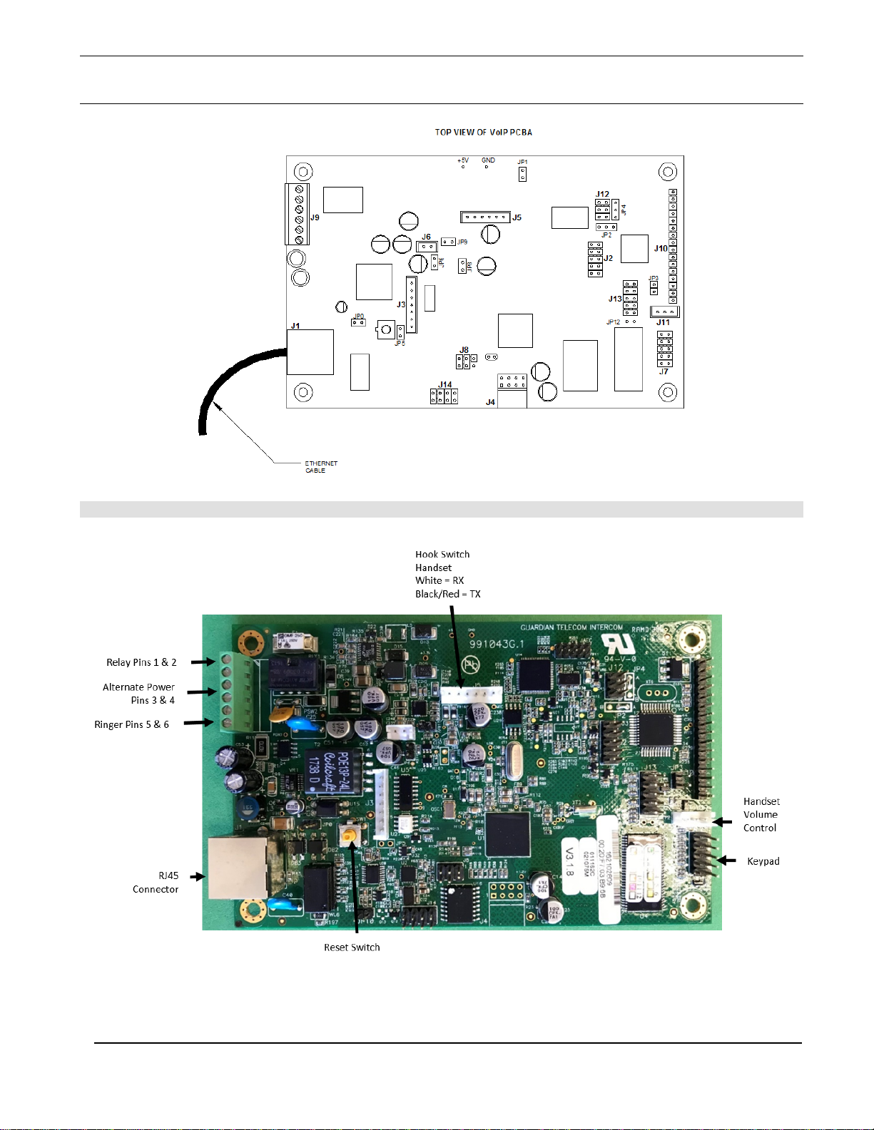
12.3. Identifying the Connector Locations and Functions ......................................17
12.4. Network Connectivity, and Data Rate...........................................................18
12.4.1. Verify Network Activity..........................................................................18
12.5. RESET Switch ..............................................................................................19
12.5.1. Announcing the IP Address..................................................................19
12.5.2. Restore the Factory Default Settings....................................................19
12.6. Adjust the Volume.........................................................................................19
13. Operation..................................................................................................................20
13.1. LED Indicator................................................................................................20
14. Specifications...........................................................................................................21
15. Field Repairs............................................................................................................22
16. Replacement Parts...................................................................................................23
17. Warranty...................................................................................................................24
18. Disclaimer.................................................................................................................24
19. Warning....................................................................................................................24
20. Service Telephone Number......................................................................................24
21. Feedback..................................................................................................................24
22. Guardian Product Return..........................................................................................25
23. Cleaning Tips for Guardian Telephones...................................................................26
24. Storage.....................................................................................................................26
Figures
Figure 1 - Typical Installation..............................................................................................6
Figure 2 - Wiring .................................................................................................................8
Figure 3 - HDE-11-VoIP & HDE-1100-VoIP Features.........................................................9
Figure 4 - HDE-11-VoIP & HDE-1100-VoIP Dimensions....................................................9
Figure 5 - HDE-11-VoIP & HDE-1100-VoIP Mounting......................................................11
Figure 6 - HDE-12-VoIP & HDE-1200-VoIP Features.......................................................12
Figure 7 - HDE-12-VoIP & HDE-1200-VoIP Dimensions..................................................12
Figure 8 - HDE-12-VoIP & HDE-1200-VoIP Mounting......................................................14
Figure 9 - Terminal Block Connections.............................................................................15
Figure 10 - Connector Locations.......................................................................................17
Figure 11 - Network Activity..............................................................................................18
Figure 12 - RESET Switch................................................................................................19

Guardian Telecom Installation and Operation
HDE-VoIP Series Telephones
Page 5
Tables
Table 1 - Connector Functions..........................................................................................17
1. Package Contents
(1) HDE-VoIP Telephone
(1) Driver bit for vandal resistant screws
(1) Mounting template for HDE-12-VoIP and HDE-1200-VoIP
Note: Installation and Operation Manual, Setup and Configuration Manual, Guardian
Discovery Utility, Interoperability Guide, VoIP Technical Support, Firmware and
Autoprovisioning template are all available at www.guardiantelecom.com.
2. Models
Part
Number Model Installation Call Button Configuration
P6995 HDE-11-VoIP Recessed Single Emergency
P6996 HDE-1100-VoIP Recessed Call button & 12 digit keypad
P6997 HDE-12-VoIP Wall Mount Single Emergency
P6998 HDE-1200-VoIP Wall Mount
Call button, Emergency button & 12
digit keypad
3. Accessories
POE – Injector – Auxiliary Power Supply (Contact Sales)
Loud Ringers and Strobe Lights
4. Updating Your VoIP Product
Please review www.guardiantelecom.com support pages to obtain the latest F/W or contact

Guardian Telecom Installation and Operation
HDE-VoIP Series Telephones
Page 6
5. Product Overview
HDE-VoIP Series Heavy Duty Emergency Telephones
The HDE-VoIP Series telephones are intended for use in public areas where direct assistance or hands-free communication is
required; they provide a hands-free, two-way link to assistance. A call may be initiated from the telephone or from the
monitoring station. The telephone may be programmed to autodial one telephone number. With an optional external signaling
alarm such as a Scream Alert* an HDE-VoIP telephone is an effective tool to alert emergency personnel of an urgent situation.
These telephones also provide the capability of monitoring the status of each unit from a remote location informing personnel
of a malfunction via event configurations. Monitoring equipment is sold separately.
The HDE-11-VoIP, HDE-12-VoIP and HDE-1200-VoIP telephones come with an ADA (American Disability Act) compliant label
(in Braille), making it well suited for University and College campuses, elevators, parking facilities, ATMs, mass transit stations,
amusement parks, senior citizen housing, hospitals and medical centers, or industrial parks.
All models have a relay contact that can energize an alerter, camera or other security device when a call is made from the
telephone. The telephone may be programmed to also energize the alerter when an incoming call is made.
*Scream Alert - a device with a VOX circuit. When the VOX detects a scream the Scream Alert will momentarily close a relay
contact, which will be used to trigger an Emergency phone call.
6. Typical System Installation
The Voice-over-IP (VoIP) HDE-VoIP Telephones are Power-over-Ethernet (PoE 802.3af) and Voice-over-IP (VoIP) two-way
communications devices that easily connect into existing local area networks (LANs) with a single cable connection. The
telephones are compatible with most SIP-based IP PBX servers that comply with SIP RFC 3261.
Figure 1 illustrates how the HDE-VoIP Telephones can be installed as part of a VoIP phone system.
Figure 1 - Typical Installation

Guardian Telecom Installation and Operation
HDE-VoIP Series Telephones
Page 7
7. Features
•Enclosure
-16 Gauge steel, zinc dichromate plated and
powder coated
-Vandal resistant buttons
-Tamper resistant screws
-Corrosion resistant hardware
•Temperature range -22
˚
to +140
˚
F ( -30
˚
to +60
˚
C)
•Optional conformal coated circuit boards are resistant
to corrosive agents (e.g. H2S, SO2and NH3) and
environments with high humidity
•Waterproof connections & stainless steel fittings for
longer life
•Modular parts for easy service
•Compatible with inductively coupled hearing-aid
devices
•Adaptive full duplex operation
•Compatible with most SIP-based IP PBX servers that
comply with SIP (RFC 3261). (Refer to the Guardian
VoIP webpage for a list of certified servers)
•Network web management interface
•Guardian discovery utility makes it easy to detect,
locate and launch the web based configuration
screens
•Product self-diagnostic testing available through web
interface
•Network adjustable speaker volume and microphone
sensitivity sets default levels. User adjustable volume
control on Handset.
•PoE 802.3af enabled (Powered-over-Ethernet) or
alternate power source
•Web Based User Interface allows remote setup of
network, product operations, updates, self-
diagnostics and other functional access.
•Auxiliary Relay – Multiple activation selectable
through web interface
•Dual speeds of 10 Mbps and 100 Mbps
•Network/Web management
•Network configurable relay activation settings
•Dial Out Extension supports the addition of comma
delimited pauses before sending additional DTMF
tones
•Network downloadable product firmware
•Tamper proof design
•Autoprovisioning and Device Configuration
Export/Import saves setup time on multiple
deployments.
•Configurable audio files
•Event Monitoring / Triggers – (Refer to VoIP
Configuration Guide – P/N: P007402)
•Three year warranty
•Peer-to-peer capable

Guardian Telecom Installation and Operation
HDE-VoIP Series Telephones
Page 8
Figure 2 - Wiring

Guardian Telecom Installation and Operation
HDE-VoIP Series Telephones
Page 9
HDE 11-VoIP HDE 1100-VoIP
Figure 3 - HDE-11-VoIP & HDE-1100-VoIP Features
Figure 4 - HDE-11-VoIP & HDE-1100-VoIP Dimensions

Guardian Telecom Installation and Operation
HDE-VoIP Series Telephones
Page 10
8. Installing the HDE-11/1100-VoIP Telephones
Follow all appropriate electrical codes and use only approved electrical fittings for the
installation.
To Avoid The Danger Of An Accidental Shock or Circuit Damage
o
If using an auxiliary power supply ensure that it is unplugged during installation.
o
If using the onboard relay to control an external device or relay ensure power is off during
installation.
Determine if power to operate the telephone will be provided via the ethernet or if external
power will be required. If external power is required install Guardian’s Auxiliary Power Supply
or equivalent.
Remove the cover screws from the front of the unit and carefully remove the front cover
assembly. Note that the electronics are attached to the front plate
Prepare an opening 7 5/
8
" (193 mm) wide, 10 ¼” (260 mm) high and 2 ½" (64 mm) deep.
Install blocking around the rough opening if required.
See: Figure 5 - HDE-11-
VoIP & HDE-1100-VoIP
Mounting
Trim the left and right edges of the opening so that the upper surface of the enclosure flanges
will be flush with the exterior of the wall when it is installed.
Install a cable gland or bushing into the 7/8” (22mm) opening in the bottom of the enclosure
for the network cable.
If additional access is required for auxiliary power or connection to the on board relay punch
another opening in the bottom of the enclosure near the original opening. Make sure that the
fittings or wiring will not interfere with the PCBA or any parts of the faceplate when it is
installed.
Thread the bare end of the Network cable out of the enclosure through the gland and opening.
If using an alternate power supply bring the wiring through the opening and into the enclosure.
If the onboard relay is to be utilized bring the wiring through the opening and into the
enclosure.
Secure the enclosure into the opening with flat head screws.
To facilitate making connections the faceplate can be temporarily attached inverted to either
side of the enclosure.
Insert the Network plug into the RJ-45 connector on the PCBA. See: Figure 2 - Wiring
Connect the alternate power supply to the terminal block if it is used.
See: Figure 9 - Terminal
Block Connections and
Section 12.2 Connecting
a Device to the Auxiliary
Relay.
Connect the onboard relay wiring to the terminal block if it is used.
Commissioning
Turn on the auxiliary power supply if utilized.
Connect the telephone into the network. Allow approx. 30sec for the phone to boot up.
Determine that the telephone is properly connected by pressing the RTFM switch for less than
five seconds to announce the IP address.
Test the unit by calling to and from another unit.
Test the operation of the on board relay if it is utilized.
Ensure all connections are tight, then replace and secure the faceplate. Use the driver bit
provided to install the tamper resistant screws. Tip: Store the driver bit in a
secure place for future use.
Programming
Set up and configure if changes are required to the default settings.
Tip: See Manual P007402
- Setup and Configuration
Test the unit by making calls to and from another unit.

Guardian Telecom Installation and Operation
HDE-VoIP Series Telephones
Page 11
Figure 5 - HDE-11-VoIP & HDE-1100-VoIP Mounting

Guardian Telecom Installation and Operation
HDE-VoIP Series Telephones
Page 12
Figure 6 - HDE-12-VoIP & HDE-1200-VoIP Features
Figure 7 - HDE-12-VoIP & HDE-1200-VoIP Dimensions

Guardian Telecom Installation and Operation
HDE-VoIP Series Telephones
Page 13
9. Installing the HDE-12/1200-VoIP Telephones
Follow all appropriate electrical codes and use only approved electrical fittings for the
installation.
To Avoid The Danger Of An Accidental Shock or Circuit Damage
o
If using an auxiliary power supply ensure that it is unplugged during installation.
o
If using the onboard relay to control an external device or relay ensure power is off during
installation.
Determine if power to operate the telephone will be provided via the ethernet or if external
power will be required. If external power is required install Guardian’s Auxiliary Power Supply
or equivalent.
Remove the cover screws from the front of the unit and carefully remove the front cover
assembly. Note that the electronics are attached to the front plate
Install a cable gland or bushing into the 7/8” (22mm) opening in the bottom of the enclosure
for the network cable.
If additional access is required for auxiliary power or connection to the on board relay punch
another opening in the bottom of the enclosure near the original opening. Make sure that the
cable gland, bushing or wiring will not interfere with the PCBA or any parts of the faceplate
when it is installed.
Choose a wall location that is free of obstructions and permits space for cable or conduit runs.
See: Figure 7 - HDE-12-
VoIP & HDE-1200-VoIP
Dimensions
Ensure mounting can support 7lbs (3kg) and any additional foreseeable load.
Use the template provided or the enclosure itself to locate and drill holes for #8 or M4
mounting screws.
For convenience while connecting wiring the faceplate may be temporarily mounted inverted
to either side of the enclosure.
Thread the bare end of the Network cable out of the enclosure through the gland and insert
the plug into the RJ-45 connector on the PCBA.
See: Figure 2 - Wiring
If using an alternate power supply bring the wiring into enclosure and connect to the terminal
block.
See: Section 12.2
Connecting a Device to the
Auxiliary Relay and Figure
9 - Terminal Block
Connections.
If the onboard relay is to be utilized bring the wiring into enclosure and connect to the terminal
block.
Commissioning
Connect the auxiliary power supply if utilized.
Connect the telephone into the network. Allow approx. 30sec for the phone to boot up.
Determine that the telephone is properly connected by pressing the RTFM switch for less than
five seconds to announce the IP address.
Test the unit by calling to and from another unit.
Test the operation of the on board relay if it is utilized.
Ensure all connections are tight, then replace and secure the faceplate. Use the driver bit
provided to install the tamper resistant screws. Tip: Store the driver bit in a
secure place for future use.
Programming
Set up and configure if changes are required to the default settings.
Tip: See Manual P007402
- Setup and Configuration
Test the unit by making calls to and from another unit.

Guardian Telecom Installation and Operation
HDE-VoIP Series Telephones
Page 14
Figure 8 - HDE-12-VoIP & HDE-1200-VoIP Mounting

Guardian Telecom Installation and Operation
HDE-VoIP Series Telephones
Page 15
10. Supported Protocols
The HDE-VoIP Telephone with Keypad supports:
●SIP (Session Initiation Protocol)
●HTTP Web-based configuration
Provides an intuitive user interface for easy system configuration and verification of HDE-VoIP Telephone with
Keypad operations.
●DHCP Client
Dynamically assigns IP addresses in addition to the option to use static addressing.
●TFTP Client
Facilitates hosting for the Autoprovisioning configuration file.
●RTP
●RTP/AVP - Audio Video Profile
●Facilitates autoprovisioning configuration values on boot
●Audio Encodings
PCMU (G.711 mu-law)
PCMA (G.711 A-law)
G722.1 (Siren7)
G722.2 (AMR-WB)
G729.1 (G729J & G729EV)
11. Supported SIP Servers
As a SIP device, this product will operate with most IP PBX servers.
12. HDE-VoIP Telephones Wiring
12.1. Connections
Figure 9 shows the pin connections on the J9 (terminal block). This terminal block can accept a wire range from 16
AWG to 26 AWG.
Note: As an alternative to using PoE power 24 VDC at 1A can be supplied to the terminal block.
Figure 9 - Terminal Block Connections

Guardian Telecom Installation and Operation
HDE-VoIP Series Telephones
Page 16
12.2. Connecting a Device to the Auxiliary Relay
The HDE-VoIP Telephone incorporates one on-board relay located on the PCBA, which
enables users to control a low current external relay or device. An external relay could control a
ringer, strobe light, door lock or any other apparatus. The on board relay is protected by a 1
Amp, non-replaceable fuse. Power switched by the relay should not exceed the
rating of the fuse. Consideration of a safety factor is recommended.
See: Figure 9 - Terminal
Block Connections
Warning: The relay circuitry contains a non-replaceable 250VAC 1A fuse. If the fuse
blows the board must be returned to Guardian or an approved service center for repair.
The Telephone relay activation time is selectable through the web interface on the Device
Configuration Page. The relay is controlled by DTMF tones generated from the phone to which
the VoIP phone is connected; no matter which one initiated the call. The DTMF tones are
selectable from the web interface as well.
See: Manual P007402
Setup and Configuration
Note: The three-digit code for the auxiliary relay must be sent in conformance with RFC2833
DTMF generation.
Note: Firmware version 3.4.0 or later requires a "#" to execute the DTMF command. Example
321# - activate relay.

Guardian Telecom Installation and Operation
HDE-VoIP Series Telephones
Page 17
12.3. Identifying the Connector Locations and Functions
See Figure 10 and Table 1 to identify the connector locations and functions.
Figure 10 - Connector Locations
Connector Function
J1 PoE Network Connection (RJ-45)
J2 Hands free Microphone Interface/LED Interface
J3 Not used
J4 JTAG Interface
J5 Handset/Reed Switch Interface
J6 Speaker Interface
J7 Keypad Interface
J8 RS232 Port
J9 Terminal Block (see Figure 9)
J10 Not used
J11 Switch Pushbutton
J12 ISP-DIP/Debug UART
Table 1 - Connector Functions

Guardian Telecom Installation and Operation
HDE-VoIP Series Telephones
Page 18
12.4. Network Connectivity, and Data Rate
When you plug in the Ethernet cable or power supply:
• The square, green Link light above the Ethernet port indicates that the network connection has been
established (see Figure 11). The Link light changes color to confirm the auto-negotiated baud rate:
• This light is yellow at 10 Mbps.
• It is orange at 100 Mbps.
12.4.1. Verify Network Activity
The square, yellow Activity light blinks when there is network activity.
Figure 11 - Network Activity

Guardian Telecom Installation and Operation
HDE-VoIP Series Telephones
Page 19
12.5. RESET Switch
When the Telephone is operational and linked to the network use the Reset Test Function Management
(RESET) switch (Figure 12), on the Telephone board to announce the Telephone’s IP Address, and test that
the audio is working (see Section 12.5.1). The message will come through the speaker.
Figure 12 - RESET Switch
12.5.1. Announcing the IP Address
To announce a telephone’s current IP address:
1. Press and release the RTFM switch (SW1). Do not hold more than five seconds.
Note The telephone will use DHCP to obtain the new IP address (DHCP-assigned address or
default to 10.10.10.10 if a DHCP server is not present).
Note Pressing and holding the RTFM switch for longer than five seconds will restore the
telephone to the factory default settings.
12.5.2. Restore the Factory Default Settings
When troubleshooting configuration problems, it is sometimes convenient to restore the device to a
known state.
Note:Each Telephone is delivered with factory set default values.
To set the factory default settings:
1. Press and hold the RTFM switch (SW1) for more than five seconds.
2. The telephone announces that it is restoring the factory default settings.
Note The telephone will use DHCP to obtain the new IP address (DHCP-assigned address or
default to 10.10.10.10 if a DHCP server is not present).
12.6. Adjust the Volume
You can adjust the volume through the Device Configuration Page.

Guardian Telecom Installation and Operation
HDE-VoIP Series Telephones
Page 20
13. Operation
HDE-11-VoIP & HDE-12-VoIP EMERGENCY TELEPHONES
Press the EMERGENCY button. The pre-programmed telephone number
automatically dials. If the unit is equipped with an external signaling device, it
will also activate. The LED will indicate when a connection has been made. A
conversation can now take place.
HDE-1100-VoIP CALL TELEPHONE
TO CALL - Press the PUSH TO CALL button, wait for dial tone then dial the
number. If a speed dial extension was programmed in the phone will
automatically dial that extension. A conversation can now take place.
HDE-1200-VoIP EMERGENCY/CALL TELEPHONE
EMERGENCY - Press the EMERGENCY button. The pre-programmed
telephone number automatically dials. If the unit is equipped with an external
signaling device option, it will also activate. The LED will indicate when a
connection has been made. A conversation can now take place.
TO CALL - Press the PUSH TO CALL button, wait for dial tone then dial the
number. If a speed dial extension was programmed in the phone will
automatically dial that extension. A conversation can now take place.
NOTE: The Emergency call always takes priority over a regular call. In the
event the emergency button is pressed while a regular call is in progress the
regular call will be disconnected and the emergency call will proceed.
13.1. LED Indicator
Action
Phone Status
LED Status
Press EMERGENCY button
or CALL button and dial
Phone dials pre-programmed number or
number dialed
Off
Phone linked or connected to dialed
number
Steady on
This manual suits for next models
8
Table of contents
Popular Emergency Phone manuals by other brands

PPP Taking Care
PPP Taking Care Your Personal Alarm Setup & user guide

CASTLE
CASTLE Care-Call user guide

ooma
ooma Safety Phone 700-0129-203 quick start guide

CVI
CVI ViAC-RTK Installation and operation manual

Linear
Linear PERS-2400 PERSONAL EMERGENCY REPORTING SYSTEM... Installation instructions and instructions for use

Viking
Viking E-1600A-GT-EWP Technical practice

Rath
Rath 2100-CL9 Installation & operation manual

Rath
Rath SmartRescue 5 Installation & operation manual

RATH MICROTECH
RATH MICROTECH SMARTPHONE III Simplified Programming Instructions

Viking
Viking E-1600A-BLT-EWP Technical practice

JNY Safetycare
JNY Safetycare Medifone user guide

Bosch
Bosch Carephone 61 Installation