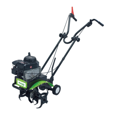
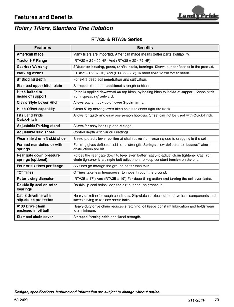
The Handy THPMT User manual

OPERATOR’S MANUAL & PARTSLIST
PETROL MINI TILLER –THPMT
Spares & Support: 01793 333212
www.thehandy.co.uk
Before use, please read & understand this manual, paying
particular attention to the safety instructions.
193820001 30/03/2015

CONTENT
S
SAFETY INSTRUCTIONS
2
FUEL
3
SPECIFICATION
3
ASSEMBLY
4
OPERATION
5
MAINTENANCE
6-7
PARTS DIAGRAM AND LIST
8-9
EC DECLARATION OF CONFORMITY
10
WARRANTY POLICY
11-12

SAFETY
INSTRUCTIONS
Read and understand the owner’s manual and labels affixed to the tiller. Learn its
application and limitations as well as the specific potential hazards. Retain these
instructions for reference.
Use sturdy footwear and protect exposed parts of your body. Wear heavy duty
gloves, preferably made of leather. Youmay wish to also have eye and ear
protection.
Do not operate the tiller if you are tired, ill or under the influence of alcohol or drugs.
Do not smoke when using the tiller and ensure caution when handling fuel.We
recommend you fuel the machine at least 3m awayfrom where you wish to work in
case any spilt fuel ignites when starting the engine.
Ensurethatbystanders,childrenandpetskeepwellawaywhenstarting or cutting - at
least 15m.
Inspect the tiller, and in particular the tilling tines, before use for any worn or
damaged parts. Do not use until the parts are repaired or replaced.
Before starting the engine make sure you have a clear work area and secure footing.
Always carry the tiller with the engine stopped and never walk away and leave the
engine running.
Never lay the hot tiller down on dry grass or any combustible material where there is
a risk of fire from the hot engine.
Only use the tiller in good light and visibility. Do not use on frozen ground.
Please recycle the cardboard packaging in which the tiller isdelivered.
Always shut off the engine before setting itdown.

FUEL
Petrol is very flammable. Do not use or fuel the tiller anywhere near a flame, sparks
or while smoking. Allow the engine to cool beforere-fuelling.Fueltheengineatleast
3 metresawayfromyourworkarea.
Fuel the machine only once you are happy the machine has been completely
assembled
Use a mixture of 25 parts unleaded petrol to 1 part 2-stroke engineoil (25:1) & mix in
a purpose produced 2-stroke mixing bottle (Handy Part: HP-120). Agitatewell.
Unscrew the fuel cap, and fuel the machine to 80% capacity.Fasten the fuel cap
tightly avoiding any cross threading and wipe up any spillages. Make sure the tiller is
ina horizontal position (Stood on its tines & wheels) when fuelling.
Ensure that any stored petrol or 2-stroke petrol/oil mixture is stored for 4-6 weeks
maximum. Any 2-stroke petrol/oil mixture should be clearly markedin a separate
can. If the tiller is notgoing to be used for a long periods, drain the mixture from the
fuel tank,start the engine and drain the carburetor of any remaining fuel.
Dispose of any unwanted 2-stroke mixture at an authorisedrecycling point.
SPECIFICATION
Model
THPMT
Engine
1.2kw Air cooled lowmaintenance
Displacement
42.7cc
Fuel TankCapacity
1200ml
Usage Time for Full Tank
Approx 60mins
Tines
6 teeth/22.5cm diameter
TillingWidth
30cm
TillingDepth
20cm
Petrol Oil Mixture
25:1
Starting System
Recoil
Low Noise
<105dB(A)
Net Weight
15kg

ASSEMBLY
Before commencing assembly, unpack the contents of the box and check that
nothingis damaged.
Handlebars:
Loosen the two handle knobs on the inside of the handlebars.
With the unit upright, swing the handlebars up into the operating position, takingcare
not to pinch the throttle cable or switch wires.
Tighten the handle knobs to secure in place.
Readjust the throttle cable so that they are smooth and tight against thehandlebar
assembly and ensure that the switch wires are fully connected.
To adjust the handlebar height:
Remove the knobs and mounting bolts and reinstall them through either the topor
bottom holes in the handlebar assembly.
Ensure that you tighten the handle knobs again securely.
Wheel Bracket Assembly:
If the wheel bracket assembly is not already fixed, follow these guidelines.
With the unit on its side, place the wheel bracket assembly on the underside ofthe
tine guard.
Make sure the square shoulder of the fixing bolts are pushed through the slotted
holes inthe wheel bracket.
Tighten the handlebar knob - but do not over-tighten.

OPERATION
Move the tiller to the work area before starting the engine. Transport by pushing on
the wheels, not the tines.
Oil is supplied in the machines gearbox at the factory. After the first 25 hours of use,
and then after every 50 hours of use, we recommend that the gearbox oil level is
checked and topped up with SW15-40 oil. The gearbox holds a maximum of 100ml
of oil. Regularly check for oil leaks coming from thegearbox.
Starting the Engine:
Move the On/Off Switch on the right handlebar to ON.
Move the choke lever on the left side of the engine to OFF (towards you)
Press the primer bulb 6-8 times until you see fuel flow through the transparent hose
from the fuel tank to the carburetor.
Put your left foot on the frame (if you are right handed) to help steady the machine
and pull the starter rope until the engine fires - it should only take a few pulls.
Allow the engine to run for 5 seconds and then move the choke lever halfway back
towards the ON position. Allow the engine to run for another 5 seconds to warm up,
thenmove the choke lever to the ON position.
When starting a warm engine, there is no need to prime the engine and the choke
lever should be left in the ON position.
With the engine running and the tines off the ground, gradually increase the engine
speed by pulling up the throttle control lever.
Holding the handlebars firmly, lower the tiller onto the soil. As the tines rotate, pull
back on the handles so that the tines can penetrate the soil. Once the ground has
beenbroken, continue at a moderate pace until you are familiar with the controls and
the handling ofthe tiller.
Pull the tiller backwards to improve the depth of cultivation and reduce youreffort.
If the tines are digging too deep or not enough, adjust following the below guidelines:
Tine adjustment will vary depending on the type of soil being cultivated and how it
willbe used.
Stop the engine and loosen the two handlebar knobs on the tine guard.
Slide the wheel bracket assembly down for shallower digging and up for deeper.
Tighten the wing nuts again, making sure that the carriage bolts are properlyseated
through the bracket.
Totransport, slide the wheel bracket assembly all the way down, tilt the unit back so
that the tines clear the ground and push to the next location using the wheels.

MAINTENANCE
Keeping your tiller in top running condition will prolong its life and help you obtain
optimum performance whenever you wish to till yourgarden.
Cleaning:
Clean the tiller underneath the tine shield after each use. It is easier to clean off soon
after use before it has had time to dry. Turn the engine off and allow it to cool down
before cleaning off the tines and wiping with an oilycloth.
Air Filter:
Check and clean the Air Filter regularly to ensure optimum performance.
Remove the air filter cover, take out the filter and wash in lukewarm water. Allow to
dry completely and then refit. If the air filter is damaged in any way, replace with an
authorised replacement part.
Spark Plug:
Check the spark plug periodically and ensure that the gap between the electrodesis
0.0020in/0.5mm.
To remove, used the universal wrench supplied.
If the spark plug is clogged with carbon, clean thoroughly with a wire brush or
replace with a Champion RDJ7Yor equivalent spark plug. Take care not to allow dirt
into the cylinder whilst the spark plug is removed. Plugthe hole with a clean rag (not
tissue) during theoperation.
Idle Adjustment Screw:
The tines should not rotate when the engine is idling (throttle control lever not in
use). If they do, turn the adjustmentscrew anti-clockwise a few degrees. The
adjuster is located just above and to the right of the primer bulb. If after adjustment,
the tines still rotate, it is recommended that the machine is inspected by your local
approved service/warranty dealer.
Storage:
When storing the tiller for any length of time it is important to drain down the fuel,
both inthe tank and the carburetor. Either drain the fuel manually or run the engine
until it uses upall the fuel.
Remove the spark plug and add a few drops of oil into the spark plughole.
Pull the starter cord gently to confirm that a film of oil covers the engine inside.
Refit the spark plug and tighten. Clean dirt or dust from the cutter blade and the
outside of the machine and wipe with an oily cloth. Store in a dryplace.

MAINTENANCE
Adjusting and Changing theTines:
Replace all four tines at the same time because they will wear evenly during normal
use. Work on one side at a time.
Put the On/Off switch in the STOP position and disconnect the spark pluglead.
Remove the clevis pin clips and clevis pins from the tine.
Remove the tines from the shaft.
Clean and using maintenance oil, lubricate the shaft.
The tines are stamped L or R to identify their position on each side of the gearbox
when facing the front of the unit.
Replace the tines onto the shaft with the hubs of the tines facingeach other.
Before you reinstall the clevis pins and pin clips, ensure that the tips on the tines are
staggered when compared to each other.
Repeat this procedure on the opposite side.
When installed correctly, there will be an R and L tine on both sides of the gearbox;
these letters will line up in the same direction for each side.

PARTS DIAGRAM- MACHINE
No
Part No
Description
Qty
No
Part No
Description
Qty
1
TH127-1
Engine
1
19
TH127-19
Sponge Cover
1
2
TH127-2
Handle
1
20
TH127-20
Outer Blade
2
3
TH127-3
Handle Set
2
21
TH127-21
Inner Blade
2
4
TH127-4
Switch
1
22
TH127-22
Wheel
2
5
TH127-5
ThrottleTrigger
1
23
TH127-23
GearboxAssy
1
6
TH127-6
Throttle Cable
1
30
TH127-30
Wheel Axle
1
7
TH127-7
Switch Wire
1
38
TH127-38
Pin
4
8
TH127-8
Star Nut
2
39
TH127-39
“R” Clip
4
9
TH127-9
Round Sq Neck Bolt
M6x40
2
40
TH127-40
Round Sq Neck Bolt
M6x25
2
10
TH127-10
Bracket
1
41
TH127-41
E-Type Card Ring+Flat
Pad 10
2+4
11
TH127-11
Clutch Housing
1
42
TH127-42
M6 Nut Dish
2
12
TH127-12
Holder on Splint
1
43
TH127-43
Hex Bolt M6x25
5
13
TH127-13
Holder
1
44
TH127-44
Flat Pad+Elastic Pad 6
8+8
14
TH127-14
Holder under Splint
1
45
TH127-45
Hex Bolt M6x16
5
15
TH127-15
Shaft
1
46
TH127-46
Nut M6
8
16
TH127-16
Oil Bearing
2
47
TH127-47
Round Sq Neck Bolt
M6x35
4
17
TH127-17
Aluminium
1
48
TH127-48
Hex Screw M5x25
6
18
TH127-18
Guard
1
50
TH127-50
Hex Screw M6x30
4

PARTS DIAGRAM- ENGINE
No
Part No
Description
Qty
No
Part No
Description
Qty
1
TH127-1E
Bolt M5x16
1
36
TH127-36E
Bolt M5x20
1
2
TH127-2E
Air Filter Cover
1
39
TH127-39E
Engine Cowl
1
3
TH127-3E
Filter Cover
1
39a
TH127-39EA
Bolt M5x12
1
4
TH127-4E
Fiter
1
43
TH127-43E
Spark Plug
1
5
TH127-5E
Bolt M5x55
1
45
TH127-45E
Muffler Gasket
1
6
TH127-6E
Air Filter CombAssy
1
46
TH127-46E
Muffler
1
7
TH127-7E
Carburetor
1
47
TH127-47E
Washer
1
8
TH127-8E
Carburetor Gasket
1
48
TH127-48E
Bolt M6x55
1
9
TH127-9E
Boot Intake
1
49
TH127-49E
Muffler Cover
1
11
TH127-11E
Gasket Intake
1
50
TH127-50E
Washer
1
17
TH127-17E
ClutchAssy
1
57
TH127-57E
Rubber Gasket
1
21
TH127-21E
Coil
1
58
TH127-58E
Fuel Tank Connect
Plate
1
33
TH127-33E
Housing-StarterAssy
1
59
TH127-59E
Fuel Tank
1
34
TH127-34E
Starter Gasket
1
60
TH127-60E
Bolt M5x20
1
35
TH127-35E
Starter Assy
1
61
TH127-61E
Fuel Tank Protector
Plate
1

EC Declaration of Conformity
We, Importer
Handy Distribution
SN3 5HY
Declare that the product
Designation: Mini Petrol Tiller
Model: THPMT
Complies with the following directives:
2006/42/EC - Machinery Directive
2004/108/EC - Electromagnetic Compatibility Directive
2010/26/EU –Emission of Pollutants
2000/14/EC amended by 2005/88/EC - Noise Emission in the Environment by
Equipment for Use Outdoors Directive.
Standards and technical specifications referred to:
EN709: 1997 + A4:2009
Name of the Notified Body:
Intertek Testing Services Shanghai
Address:
Building 86, 1198 Qinzhou Road (North), Shanghai, 200233, China
- Measured Sound Power Level: 107.47 dB (A)
- Guaranteed Sound Power Level: 110 dB (A)
Authorised signatory and technical file holder
Signature: Date: 30/03/2015
Name / title: Mr. Simon Belcher / Managing Director
Murdock Road, Dorcan, Swindon, Wiltshire, SN3 5HY.

GJ HANDY & CO LTD USER WARRANTY POLICY
1. Users Statement of Warranty
Each new machine is warranted against defective material or assembly of material under
normal usage. The warranty applies to the original purchaser and covers faulty parts and the
labour involved in replacing and repairing those parts, which are of original manufacture.
2. Period of Warranty
All Webb, Handy Pro (Brushcutter & Long Handle Hedgecutter only) and Sanli
domestic products
(a) 2 years from the original date of sale to the first domestic user.
(b) 90 days from the original date of sale to the professional/commercial user.
(c) 90 days from the original date of sale when used for hire.
(d) Engines as per the manufacturer’s warranty statement which will be supplied with the
machine.
(e) 1 year from the original date of purchase for Replacement Spare Parts (unless
normal wear & tear component, which are covered for 90 days).
(f) All machines’ must be serviced within the first 12 months from the original date of
purchase to comply with the warranty, failure to do so will invalidate the 2nd year of
the warranty.
(g) A reduced warranty period of ninety days applies to those items which are subject to
normal wear and tear (e.g. wheels, tyres, cutter bars, cylinders, bottom blades, belts,
cables, grass bags, spark plugs).
All Handy, Handy Pro (All others), Mowerland and Q-Garden domestic products
(a) 1 year from the original date of sale to the first domestic user.
(b) 90 days from the original date of sale to the professional/commercial user.
(c) 90 days from the original date of sale when used for hire.
(d) Engines as per the manufacturer’s warranty statement which will be supplied with the
machine.
(e) 1 year from the original date of purchase for Replacement Spare Parts (unless
normal wear & tear component, which are covered for 90 days).
(f) A reduced warranty period of ninety days applies to those items which are subject to
normal wear and tear (e.g. wheels, tyres, cutter bars, cylinders, bottom blades, belts,
cables, grass bags, spark plugs).
All warranty repairs must be undertaken by an authorised service dealer. These dealers
have been accredited by GJ Handy & Co Ltd and agree to only use genuine parts and follow
our repair procedures.
GJ Handy & Co Ltd reserve the right to change specifications and/or price without notice
Version 1 07-14

GJ HANDY & CO LTD USER WARRANTY POLICY
3. Not covered by this warranty
(a) The warranty policy does not cover any depreciation or damages caused by ordinary
wear, rusting or corrosion, lack of correct maintenance or operation, misuse, abuse,
lack of transportation or accident.
(b) The warranty policy does not cover any costs necessary for the standard periodic
maintenance services instructed by the operators manual, or service parts
replacement which would include oil, filters, tyres, belts, brake linings, fuses, blades,
seals and other service parts unless it can be proven that the item has evidence of
faulty manufacture.
(c) The warranty policy will not cover failure or damage caused as a result of parts or
accessories being modified without the written approval of GJ Handy & Co Ltd.
(d) The warranty policy will not cover the unit if non-genuine parts have been fitted and
as a result damage has occurred to the unit.
(e) The warranty policy is non transferable and is only applicable to the original
purchaser.
4. Disclaimer
(a) This warranty is only a remedy for defect of products. GJ Handy & Co Ltd will never
warranty in terms of the merchantability or the fitness for a particular purpose.
(b) No person is authorised to make any warranties, representations or promises,
expressed or implied, on behalf of GJ Handy & Co Ltd, or to modify the terms
conditions or limitation of this warranty policy in any way.
(c) Neither GJ Handy & Co Ltd nor any company affiliated with GJ Handy & Co Ltd shall
be liable in any event or manner whatsoever for incidental or consequential damages
or injuries, including, but not limited to, loss of crops, loss of profit, out of pocket
expenses or profits, rental of substitute equipment or other commercial losses.
5. General
(a) Most warrantable failures show up within the first few weeks of use. These failures
are usually straightforward and warranty assessment is relatively easy.
(b) Failures relating to cutter decks and belts need careful investigation, as the cause
may not always be straightforward. Look for damage to blades and pulleys especially
when the cutter belt or blade boss have snapped or cracked as this could be due to
impact damage.
(c) Customers should always refer to the operator/instruction manual when any disputed
problem arises, you will find most areas covered within the manual.
GJ Handy & Co Ltd reserve the right to change specifications and/or price without notice
Version 1 07-14


NOTES
_____________________________________________
_____________________________________________
_____________________________________________
_____________________________________________
_____________________________________________
_____________________________________________
_____________________________________________
_____________________________________________
_____________________________________________
_____________________________________________
_____________________________________________
_____________________________________________
_____________________________________________
_____________________________________________
_____________________________________________
_____________________________________________
_____________________________________________
_____________________________________________
_____________________________________________
_____________________________________________
_____________________________________________
_____________________________________________
_____________________________________________
_____________________________________________
_____________________________________________
_____________________________________________
_____________________________________________
_____________________________________________
_____________________________________________
_____________________________________________
_____________________________________________
_____________________________________________

To order spare parts and see the complete range of garden machinery and
garden equipment from Handy, visit:
www.thehandy.co.uk
Spares & Support: 01793 333212
Other manuals for THPMT
3
Table of contents
Other The Handy Tiller manuals

The Handy
The Handy THET1400 User manual

The Handy
The Handy THPMT User manual

The Handy
The Handy 193820003 User manual

The Handy
The Handy THTILL6.5-A Installation and maintenance instructions
The Handy
The Handy 1938118001 User manual

The Handy
The Handy THET-A Installation and maintenance instructions
The Handy
The Handy THPMT Installation and maintenance instructions

The Handy
The Handy THET 193874002 User manual

The Handy
The Handy TH18VT User manual

The Handy
The Handy THET1400 User manual

