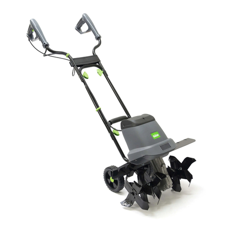
The Handy THET-A Installation and maintenance instructions

OPERATOR’S MANUAL AND PARTS LIST
800W ELECTRIC TILLER - THET-A
Sales & Helpline 01793 333212
www.thehandy.co.uk
Before use please read & understand this manual, paying particular
attention to the safety instructions.
2011 v1

Page 2
Contents
DIAGRAMS 3
SAFETY INSTRUCTIONS 7
APPLICATION CONDITIONS 8
SPECIFICATIONS AND ELECTRICAL REQUIREMENTS 8
ASSEMBLING THE TILLER 8
STARTING THE TILLER 8
TIPS 9
MAINTENANCE AND STORAGE 9
TROUBLE SHOOTING 11
PARTS DIAGRAM 12
EC DECLARATION OF CONFORMITY 14

Page 3
DIAGRAMS
1 Trigger Lever
2 Safety Switch
3 Cable Relief
4 Upper Handle
5 Carrying Handle
6 Lower Handle
7 Fender
8 Protective Shield
9 Tines

Page 4
3

Page 5

Page 6

Page 7
SAFETY INSTRUCTIONS
• Read and understand the owner’s manual and the labels afxed to the electric tiller.
Learn its application and limitations as well as the specic potential hazards. Retain
these instructions for reference.
• Check your tiller before use. Keep guards in place and in working order. You should only
work with a machine that is in good condition. If you notice any defect on the machine
that may cause damage to the operator, do NOT operate until faults have been rectied.
Replace worn or damaged parts using only original spare parts.
• Do NOT operate the electric tiller whilst under the inuence of drugs, alcohol or any
medication that could affect your ability to use the apparatus correctly.
• Dress appropriately – do NOT wear loose clothing, ties, jewellery or anything that could be
caught in the moving tines. Use of gloves and strong footwear are recommended.
• Only work in daylight or sufciently good articial light.
• Keep children and pets away from the tiller at all times and do NOT operate near
underground electric cables, telephone lines, pipes or hoses.
• Wear eye protection and a face or dust mask if working in dusty conditions.
• Before use make sure the socket ratings are correct and correspond to those indicated on
the rating label on the tiller.
• Do NOT operate on a slope that is too steep for safe operation. When on slopes, slow
down and make sure you have good footing.
• Never operate the machine with one hand and be aware that, if the tines hit stones, frozen
ground or buried roots and stumps, then it may unexpectedly bounce upward and jump
forward.
• Be aware of the extension lead and be careful not to trip over it or pass the tiller over it.
Always guide the lead away from the tines at all times and keep behind your back.
• If the tines hit a large stone, stump or other obstacle immediately turn off the machine
and check for any damage to the tines. If the machine starts to vibrate abnormally switch
off the motor immediately and check for causes.
• Always switch off the machine, disconnect the plug and wait for the tines to stop turning
before carrying out any inspection or maintenance. The tines will not stop immediately
after switching off.
• It is prohibited to move or modify any of the electrical and mechanical safety devices.
Electrical Safety:-
• The mains voltage must correspond to the one marked on the technical data plate
(230V-50Hz). Do not use any other source of power. The use of a circuit breaker is
recommended for an intervention range of 10 to 30 rated mA.
• Make sure you always know where the cable is and never pass the tiller over the cable to
avoid cutting the cable with the tines.
• Do NOT use the machine in the rain and do NOT leave it outside overnight. Try to prevent
it getting wet or being exposed to humidity.
• Check the power cable regularly to ensure it is not damaged. Only use an extension
cable which is suitable for outdoor use. If the cable is damaged arrange for a replacement
before further use.
• The mobile socket of the extension cable should be splash proof in compliance with
DIN57282 and VDE 0282 regulations; the cross section of the wire (max length 75m)
should be at least 1.5mm². Use H07RN-F harmonised cable.


Page 9
TIPS
• Hold the tiller rmly when switching on as it may jump when the tines start rotating.
• The tines will pull the tiller forward during operation – press down on the handle to dig the tines into the soil.
• By pulling the tiller backwards the tines will dig deeper and more aggressively,take care not to trip over
and keep the cable clear.
• For breaking sod or deep tilling, allow the tines to move forward to arms reach and then pull back rmly. By
repeatedly allowing the tiller to move forward and backward, cultivating will be more effective.
• If the tiller digs deep enough to stay in one spot, rock gently from side to side to move the tiller forward again.
• For preparing seed beds we recommend you use one of the patterns shown on Fig 5 – either make two
passes at right angles to each other, or make two passes side by side with the second overlapping the rst.
• Take care when transporting the machine. Always carry the tiller to avoid causing damage to the tines when
moving over hard ground.
• Switch off the power and clear the tines of all debris, roots, stones etc. regularly when using. If weeds are
wrapped round the tines you may have to remove the tines as shown later in this manual.
MAINTENANCE AND STORAGE
Before carrying out any maintenance, disconnect from the power source.
• Before each use check the cable for signs of damage and replace if necessary.
• Check that tines are not blunt and all threaded connections are securely tightened.
• At the start of the season lubricate the tines and shaft. At the end of the season we recommend that the tiller
is serviced by a specialist workshop.
Always clean the tiller after each use – wear protective gloves when cleaning the tines.
• Clean the underside of the tine housing and the protective shield and fender with a scrubbing brush or cloth
dampened with mild soap and water. Never splash with water.
• To remove soil and debris from the tines and transmission, use a stiff brush or dampened cloth.
• Clean the ventilator and remove any remaining grass or dirt.
• Once cleaned, wipe the tines and shaft dry and apply a light coat of oil.
Tines Removal and Installation
Worn tines can result in poor performance and overload the motor. Sharpen or replace tines with new ones if necessary.
To remove tines:
• Remove the lock pin from the end of the shaft.
• Take off the outer tine set from the shaft.
• Remove the lock pin and take off the inner tine set from the shaft.
• Reverse above steps to install tines.
When one or two pieces of tine are broken you can change the damaged tines instead of replacing the complete set.
• Loosen the screws from one side whilst holding the lock nuts from the other side.
• Take off the damaged tine and replace with a new one.

Page 10
Checking Transmission Lubricant (Fig 7)
• The drain screw plug (1) is located on the right side of the transmission housing.
• Lay the tiller on its left side and clean the transmission of dirt and debris. Remove the drain screw.
• Use a 5mm alan key to unscrew the plug.
• Fill up using a grease gun and a high quality automotive grade grease until it begins to seep out around the
edge of the hole of the nozzle.
• If necessary, disassemble the tines.
• Reinstall the drain screw plug.
Storage
The tiller should be stored in a dry room out of the reach of children.
At the end of the season, or the tiller is not going to be used for some time:
• Clean the tiller.
• Wipe over the metal surfaces with an oil-impregnated cloth to protect them from corrosion (non-resinous oil)
or spray a ne coat of oil onto them from a can.
• Fold the top handle down for ease of storage.

Page 11
TROUBLE SHOOTING
Problems that may arise when using the tiller and some recommended actions and checks are shown in the
table below:
Problem Probable Cause Corrective Action
Motor does not start No electricity
Defective Cable
Defective safety switch/plug
combination
Overheat protection activated
Check mains connection
Check cable, replace if necessary or have existing
cable repaired professionally
Arrange for repair in specialist workshop
1) Blades blocked – remove blockage
2) Soil too hard – move tiller forward and
backward several times slowing down the
speed. Allow motor to cool down before

restarting
Abnormal noises Blade is jammed
Lubrication leaking out
Loose bolts, nuts or other
securing components
Switch off and when completely stopped remove
objects
Arrange for repair in a specialist workshop
Tighten all components, contact specialist dealer if
noise continues
Abnormal vibration
Blades damaged or worn
Replace or have them checked by a specialist dealer
Poor results Worn blades Replace or have them checked by a specialist dealer


Page13
Position Description Quantity
TH165-1 Bearing 608Z 1
TH165-2 Worm Shaft 1
TH165-3 Bearing 6200 1
TH165-4 Coupler 1
TH165-5 Rubber Seal 2 1
TH165-6 Flexible Shaft 1
TH165-7 Motor Complete 1
TH165-8 Inductor 1
TH165-9 Cover 1
TH165-10 Sponge Strip 1
TH165-11 Screw ST3.5x16 4
TH165-12 Screw ST3.9x19 14
TH165-13 Screw M6x45 4
TH165-14 Cable Clip 2
TH165-15 Exhaust Back Cover 1
TH165-16 Screw ST3x12 ------1
TH165-17 Cable Sleeve 1
TH165-18 Screw M5x48 4
TH165-19 Capping Plug 4
TH165-20 Motor Housing 1
TH165-21 Cable Holder 1
TH165-22 Exhuast Cover 1
TH165-23 Fender 1
TH165-24 Screw M8x40 2
TH165-25 Tines Set 2 1
TH165-26 Nut M8 2
TH165-27 Ring 2
TH165-28 Transmission Case Right Section 1
TH165-29 Rubber Seal 2
TH165-30 Oil Bearing 2
TH165-31 Seal 1
TH165-32 Washer 2
TH165-33 Worm Wheel 1
TH165-34 Shaft 1
TH165-35 Transmission Case Left Section 1
TH165-36 O Ring 1
TH165-37 Drain Screw Plug 1
TH165-38 Tines Set 1 1
TH165-39 Screw M6x16 6
TH165-40 Protective Shield 1
TH165-41 Screw ST4.2x19 4
TH165-42 Screw ST4.2x32 4
TH165-43 Handle Holder 2
TH165-44 Handle Lower Section 1
TH165-45 Swing Nut 4
TH165-46 Handle Middle Section 2
TH165-47 Cable Hook 1
TH165-48 Handle Upper Section 1
TH165-49 Safety Switch Combination 1


EC Declaration of Conformity
We,Importer
Handy Distribution Ltd.
SN3 4NS
Declare that the product
Designation: 800W ELECTRIC TILLER
Model: THET-A
Complies with the following directives:
2006/42/EC- Machinery Directive
2006/95/EC- Low Voltage Directive
2004/108/EC- Electromagnetic Compatibility Directive
2000/14/EC amended by 2005/88/EC- Noise Emission in the Environment by Equipment for
Use Outdoors Directive.
The conformity assessment procedure followed was in according with Annex V of the
Directive 2000/14/EC.
-Measured Sound Pressure Level: 89.52 dB (A)
-Guaranteed Sound Power Level: 93 dB (A)
Standards and technical specifications referred to:
EN60335-1:2002+A13
EN709: 1997+A4
EN62233:2008
EN55014-1:2006
EN55014-2:1997+A1
EN61000-3-2:2006
EN61000-3-3:1995+A1+A2
Authorised signatory and technical file holder
Date: 24/11/2010
Signature:__________________
Name / title: Mr. Simon Belcher / Managing Director
Hobley Drive, Stratton St Margaret, Swindon, Wiltshire, SN3 4NS

To order spare parts and see the complete range of garden
machinery and garden equipment from Handy, visit:
www.thehandy.co.uk
Spares & Support: 01793 333212
Table of contents
Other The Handy Tiller manuals

The Handy
The Handy THPMT Installation and maintenance instructions

The Handy
The Handy 193820003 User manual

The Handy
The Handy TH18VT User manual

The Handy
The Handy THET 193874002 User manual

The Handy
The Handy THPMT User manual

The Handy
The Handy THTILL6.5-A Installation and maintenance instructions

The Handy
The Handy THET1400 User manual

The Handy
The Handy THPMT User manual

The Handy
The Handy THPMT User manual

The Handy
The Handy THET1400 User manual