The Outdoor Plus SELF-CONTAINED UNIT Installation instructions
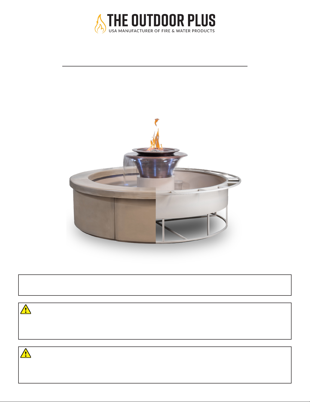
SELF-CONTAINED UNIT
INSTALLATION & OPERATION INSTRUCTIONS
www.theoutdoorplus.com
Read all instructions before you operate your Self-Contained Unit.
Save these instructions!
TO INSTALLER: Leave this manual with the Self-Contained Unit
TO CONSUMER: Keep this manual for future reference.
WARNING
Improper installation, adjustment, alteration, service, or maintenance can cause injury
or property damage. Read the installation, operating, and maintenance instructions
thoroughly before installing or servicing this equipment.
WARNING
Do not store or use gasoline or other ammable vapors and liquids in vicinity of this
or any other appliance. An LP-cylinder not connected for use shall not be stored in the
vicinity of this or any other appliance.
V.042723.3
2THE OUTDOOR PLUS | Self-Contained Unit Installation Manual
WARNING LABELS & SYMBOLS
WARNING
Do not store or use gasoline or other ammable vapors and liquids, in the vicinity of this or any
other appliance.
An LP-Cylinder not connected for use shall not be stored in the vicinity of this or any
other appliance.
For use with Natural or Propane gas only. NO SOLID FUELS TO BE USED WITH THIS SYSTEM.
DANGER
FOR OUTDOOR USE ONLY
WARNING
If the information in this manual is not followed exactly, a re or explosion may result causing
property damage, personal injury, or loss of life.
WARNING
Product is not intended to be a starter for wood or any other combustibles.
WARNING
All re pits must have a gas shut o on the outside of the exterior of the re pit to allow for
emergency shut o and maintenance.
DANGER
If you smell gas:
Shut o gas to the appliance.
Extinguish any open ame.
If odor coutinues, keep away from appliance and immediately call supplier or re department.
DANGER! CARBON MONOXIDE HAZARD
This appliance can produce carbon monoxide which has no odor.
Using it in an enclosed space can kill you. Never use this appliance in
an enclosed space such as a camper, tent, car, or home.
THIS IS A SAFETY ALERT SYMBOL
When you see this symbol in on the re feature or manual, look
for one of the following signal word panels alerting you to the
potential for personl injury, death or major properety damage.

3
WARNING LABELS & SYMBOLS
WARNING
Select a location where the re pit can be attended during operation. Never leave an operating
re pit unattended.
WARNING
Young children should be carefully supervised wehen they are in the area of the re pit.
WARNING
Flammable gas under pressure. Leaking LP-gas may cause a re or explosion if ignited causing
serious bodily injury or death. Contact a certied LP-gas supplier for repairs, or disposal of this
cylinderor unused LP-gas
WARNING
Use only in complianbce with applicable codes.
WARNING
Never alter product or conguration in any way.
Installation must conform with local codes or, in the absence of local codes, with the National Fuel Gas
Code, ANSI Z223.1 / NFPA 54, or International Fuel Gas Code. The appliance, when installed, must be elec-
trically grounded in accordance with local codes or, in the absence of local codes, with the National Electric
Code, ANSI/NFPA 70, if applicable.

4THE OUTDOOR PLUS | Self-Contained Unit Installation Manual
WARNING LABELS & SYMBOLS
- The Outdoor Plus Company, Inc./TOPFIRES recommends that our products are installed by professionals locally
licensed by the authority having jurisdiction in gas piping. All installation instructions must be followed to ensure
proper performance and safety. The Outdoor Plus Company, Inc./TOPFIRES assumes no responsibility for problems
relating to the installation.
- To qualify for warranty, all instructions must be strictly followed. Otherwise, warranty may be void. Never alter
product or conguration in any way.
- Annual servicing should be handled by professionals certied in the US by the National Fireplace Institute (NFI) as
NFI Gas Specialists or in Canada by WETT (Wood Energy Technical Training).
- It is the installer’s responsibility to ensure a safe installation and to educate the end-user regarding the features,
safety recommendations and proper operation of this product.
-Installers must carefully follow the instructions in this manual to prevent personal injury or property loss.
These instructions contain information critical to the safe installation and operation of the re pit.
- Instructions are updated as needed. It is the responsibility of the installers to check for product updates and
installation manual updates at www.theoutdoorplus.com/documents/ prior to installation.
- It is the responsibility of the installer to follow:
- The National Fuel Gas Code, ANSIZ223.1/NFPA54 or International Fuel Gas Code.
- Natural Gas and Propane Installation Code CSA B149.1 or CSA B149.2.
- The National Electrical Code, ANSI/NFPA70. In Canada, Canadian Electrical Code CSA22.1.
- Local codes
- Only use gas/fuel type specied for this re pit as noted on the re pit control box label. NEVER use an alternative
fuel to include bio-fuel, ethanol, lighter uid or any other fuel.
- Gas pressure and type should be checked prior to installation and use.
Natural Gas Fire Pit: Supply Pressure: Minimum: 6.0 inches W.C.; Maximum: 7.0 inches W.C.
LP Gas: Supply Pressure: Minimum: 8.0 inches W.C.; Maximum: 11.0 inches W.C.
IMPORTANT SAFETY INFORMATION FOR INSTALLERS:
Leave this manual with the end-user and instruct them to retain it for future reference.
Instructions and product updates are also available at www.theoutdoorplus.com under
the Manuals/Documents tab.
IMPORTANT SAFETY INFORMATION FOR END USERS:
Never leave an operating re pit unattended or with someone not familiar with its
operation or emergency shut-o locations. Both children and adults should be alerted to
the hazards of high surface temperatures and should stay away to avoid burns and clothing
ignition. Young children should be carefully supervised when they are in the area of re pit.
Keep the appliance area clear and free from combustible materials,
gasoline, and other ammable vapors and liquids.

5
WARNING LABELS & SYMBOLS
DANGER FLAMMABLE GAS UNDER PRESSURE.
LEAKING LP-GAS MAY CAUSE A FIRE OR EXPLOSION IF IGNITED
CAUSING SERIOUS BODILY INJURYOR DEATH.
CONTACT LP GAS SUPPLIER FOR REPAIRS, OR DISPOSAL OF THIS CYLINDER
OR UNUSED LP-GAS.
WARNING FOR OUTDOOR USE ONLY.*
DO NOTUSE OR STORE CYLINDER IN A BUILDING,
GARAGE OR ENCLOSED AREA.
DO NOT REMOVE, DEFACE, OR OBLITERATE THIS LABEL
*EXCEPT AS AUTHORIZED BY ANSI/NFPA 58.
DANGER: Do not store a spare LP Cylinder under or near a barbecue grill, or other heat sources.
NEVER ll an LP cylinder beyond 80% full: a re causing death or serious injury may occur.
WARNING:
Know the order of LP-gas. If you hear, see
or smell leaking LP-gas, immediately get
everyone away from the cylinder and call the
Fire Department. Do not attempt repairs.
Caution your LP-gas supplier to:
WHEN CONNECTING FOR USE:
Use only in compliance with applicable codes.
Read and follow manufacturer’s instructions.
Consult manufacturer’s instructions
concerning the cylinder connection provided
with you appliance.
Be sure regulator vent is not pointing up.
Turn off all valves on the apploiance.
Do not check for gas leaks with a match or
open ame. Apply soapy water at areas
marked “X”. Open cylinder valve. If bubble
appears, close valve and have LP-gas
service person make needed repairs. Also,
check appliance valves and connections to
make sure they do not leak before lighting
appliance.
Light appliance(s) following manufacturer’s
instructions.
When appliance is not in use, keep the
cylinder valve closed.
LP-gas is heavier than air and may settle in
low places while dissipating.
Contact with the liquid contents of cylinder
will casue freeze burns to the skin.
Do notallow children to tamper or play with
cylinder.
When not connected for use, keep cylinder
valve turned off. Self contained appliances
shall be limited to a cylinder of 30 lb
capacity or less.
Do not use, store or transport cylinder where
it would be exposed to high temperatures.
Relief valve may open allowing a large amount of
ammable gas to escape.
When transporting, keep cylinder secured in an
upright position with cylinder valve turned off.
Be certain cylinder is purged of trapped
air prior to rst lling.
Be certain not to over ll the cylinder.
Be certain cylinder requalication date is
checked.

6THE OUTDOOR PLUS | Self-Contained Unit Installation Manual
TABLE OF CONTENT
SAFETY INFORMATION
Warning Labels & Symbols...................................................002
SITE PREPARATION
Selecting A Information............................................................007
Electrical & Gas Supply Information.......................................008
Water Connection.....................................................................009
ASSEMBLY
Fire Feature Installation...........................................................010
Enclosure Clearance.................................................................012
Water Feature Installation.......................................................013
Leveling Your Fire & Water Feature........................................015
Electrical Wiring Schematic.....................................................016
START-UP & TESTING
Gas Leak Test............................................................................018
Start Up.....................................................................................019
MAINTENANCE & TROUBLESHOOTING
Self-Contained Unit Maintenance...........................................022
Troubleshooting Guide.............................................................023
Replacement Parts....................................................................024
WARRANTY & SUPPORT
Customer Support Contact Information................................025
Warranty Information..............................................................026
WARNING: CALIFORNIA PROP 65
This product can expose you to chemicals including lead, which is known to the State of California
to cause cancer and birth defects or other reproductive harm. For more information go to
www.P65Warnings.ca.gov.
7
SITE PREPARATION |Selecting A Location
SELECTING THE LOCATION:
Choosing the right location for your Self-Contained Unit is crucial to ensuring a safe and enjoyable experience.
Before you begin assembling your fountain, you should carfully conside the following factors when selecting a
location:
1. Ventilation: Some self-contained unit have both re & water feature. If you unit have these both elements which
require proper ventilation to prevent any harmful build-up of carbon monoxide or other gases. Always install the
fountain in a well-ventilated area with plenty of fresh air ow.
2. Wind: Avoid installing your self-contained unit in a area with high-winds, as this can cause safety hazards and
negatively aect the performance of your unit.
3. Clearance: The re & water fountain should be installed in an area with enough clearance around it, free from
any obstructions.
4.Water Source: Make sure you chosen location has access to a reliable and and adequate water source for the
fountain’s water feature.
5. Gas and Electrical Supply: The Fire & Water Fountain requires a gas and electrical supply to operate, so ensure
that the location you choose has easy access to these connections.
6. Level Surface: A level surface is essential for proper installation and function of the fountain. Make sure the
installation site is level, at, and stable.
7. Visibility: The Fire & Water Fountain is an impressive visual display, so choose a location that allows for
maximum visibility, both for yourself and your guests.
ELECTRICAL & GAS SUPPLY
The Fire & Water Fountain requires both electrical and gas supplies to operate. It’s important to ensure that both of
these supplies are installed correctly to prevent any safety hazards or damage to the fountain.
Electrical Supply:
1. Voltage: The Fire & Water Fountain requires a specic voltage to operate. Check page 001, to see the Wiring
Diagram.
2. Outlet location: The electrical outlet should be installed in a location that is easily accessible and is not too far
from the fountain. It’s important to avoid using extension cords or power strips as they can create safety hazards.
3. Ground Fault Circuit Interrupter (GFCI): The electrical outlet should be installed with a GFCI to prevent
electrical shocks. Ensure that the GFCI is working correctly before connecting the fountain.
CAUTION
The Fire & Water Fountain is a large and heavy structure that can create safety hazards if not
placed in a suitable location. Always ensure that the fountain is installed on a stable and level
surface and that there is enough clearance around the fountain for safe movement.
CAUTION
Failure to properly select a location for your Fire & Water Fountain can result in injury or property
damage. If you are unsure about any aspect of the location selection process, consult a licensed
professional for assistance.

8THE OUTDOOR PLUS | Self-Contained Unit Installation Manual
SITE PREPARATION |Electrical & Gas Supply Information
GAS PRESSURE:
Natural Gas
Supply Pressure: Minimum 3.5” W.C. Maximum 7.0” W.C.
Outlet Pressure: 3.5” W.C.
Liquid Propane
Supply Pressure: Minimum 8.0” W.C. Maximum 11.0” W.C.
Outlet Pressure: 10.0” W.C.
ELECTRONICS:
- CSA Certied ANSI Z21.97-(2017) / CSA 2.41-(2017) certied
- If you plan to install your re & water feature within 5 feet of
water, the electrical supply must be 12 or 14 VAC.
- The Thermocouple Flame Sense operates by sensing the
heat produced by the ame and producing an electrical
signal to keep the gas valve open. In the event of a ame
outage, the thermocouple sends a signal to close the gas
valve, thereby stopping the gas supply and preventing the
accumulation of gas that can lead to re or explosion.
- The Low Voltage Electronic System features LEDdiagnostics
that aid in eld service and troubleshooting. The LED
diagnostics display visual feedback on the electronic
system’s status, facilitating the identication and resolution
of any problems that may arise.
GAS VALVES & PILOT COMPONENTS:
- All conneectors are water resistant
- Certied CSA ANSI Z21.97-(2017) / CSA 2.41-(2017) certied.
- The Pilot is designed to have robust ame pattern that is wind-resistant.
- The coils are encapsulated to protest against moisture ensuring that the electrical componets remain safe and
operational.
GAS REQUIREMENTS:
The Fire & Water Fountain can be powered by either
natural gas or propane, both gases are clean-burn-
ing fuels that produce low emission and are widely
available. It is important to note that both natural
gas and propane require special safety precautions
to prevent gas leaks and ensure proper operation
of the fountain. Proper installation, maintenance,
and safety procedures must be followed when using
either fuel to ensure the safe and reliable operation
of the fountain.
120 VAC PRIMARY INPUT - 300 W OUTPUT
DISTANCE
FEET
5FT
10FT
20FT
30FT
40FT
50FT
60FT
70FT
80FT
90FT
100FT
110FT
12VAC
12VAC
12VAC
12VAC
13VAC
13VAC
13VAC
13VAC
13VAC
14VAC
14VAC
14VAC
12VAC
12VAC
12VAC
13VAC
13VAC
13VAC
14VAC
14VAC
14VAC
12VAC
12VAC
13VAC
13VAC
14VAC
14VAC
12VAC
13VAC
13VAC
14VAC
6AWG 8AWG 10AWG 12AWG

9
SITE PREPARATION |Water Connection
WATER CONNECTION:
Connecting the water system on the Fire & Water Fountain is an important step in the installation process. The
fountain uses a water supply line to provide water to the fountain and it’s components. It is important to ensure
that the water supply line is properly installed and connected to a shut-o valve that can be easily accessed in case
of an emergency. We recommend that you keep a copy of the checklist on hand throughout the installation process
as a quick refrence.
Use this checklist to ensure that the water system on your re & water fountain is properly connected:
Check that the water supply line is properly sized and installed.
Ensure that the water supply line is connected to a shut-o valve that can be easily accessed in case of
emergency.
Locate the water inlet on the fountain’s base.
Connect the water supply line to the fountain’s water pump using a hose connector.
Turn on the water supply and check for any leaks or issues with water ow.
Adjust the water pressure to the recommended level for the fountain.
Regularly inspect the water supply line and connections for signs of wear or damage.
Clean the water supply line and check the shut-o valve periodically.
Inspect the water inlet for any clogs or blockages that could impact performance.

10 THE OUTDOOR PLUS | Self-Contained Unit Installation Manual
ASSEMBLY |Fire Featrure Installation
PROPER LOCATION:
Ensure that the fountain is located in an area that meets all local building and safety codes. Check for adequate
ventilation, clearance from combustible materials, and appropriate electrical and gas connections.
PROPER VENTING:
The Fire & Water Fountain needs to have a proper venting system that ensure safe and ecient operation of the
unit. The fountain uses a gas-powdered burner system to produce ames, which produce heat and carbon dioxide.
Failure to meet any of these requirements may void the warranty. The manufacturer reserves the right to inspect
the installation and determine whether it meets the warranty requirements.
WARNING
For outdoor use only and must comply with instructions and clearances.
WARNING
The water basin must be supplied power via GFCI protected circuits.
WARNING
Improper venting of the Fire & Water Fountain can result in the buildup of harmful gases, which
can be a serious safety hazard.
WARNING
FIRE OPTION: For a water basin with the re option refer to the correct re pit installation
instructions contained in this document.
IMPORTANT
WARRANTY REQUIRMENTS: The Fire & Water Fountain must be installed in a location that meets
all local building and safety codes, including adequate ventilation, clearance from combustible
materials, and appropriate electrical and gas connections.
IMPORTANT
WARRANTY REQUIRMENTS: The Fire & Water Fountain is a carefully designed and engineered
product that should not be altered in any way. Any modication to the fountain may void the war-
ranty. To ensure that your fountain is covered under warranty, please follow the installation and
operation instructions provided in this manual. If you have any questions or concerns about the
installation or operation of the fountain, please contact the manufacturer or a qualied
professional. Failure to follow the instructions provided in this manual or any alterations made to
the fountain will void the warranty.
11
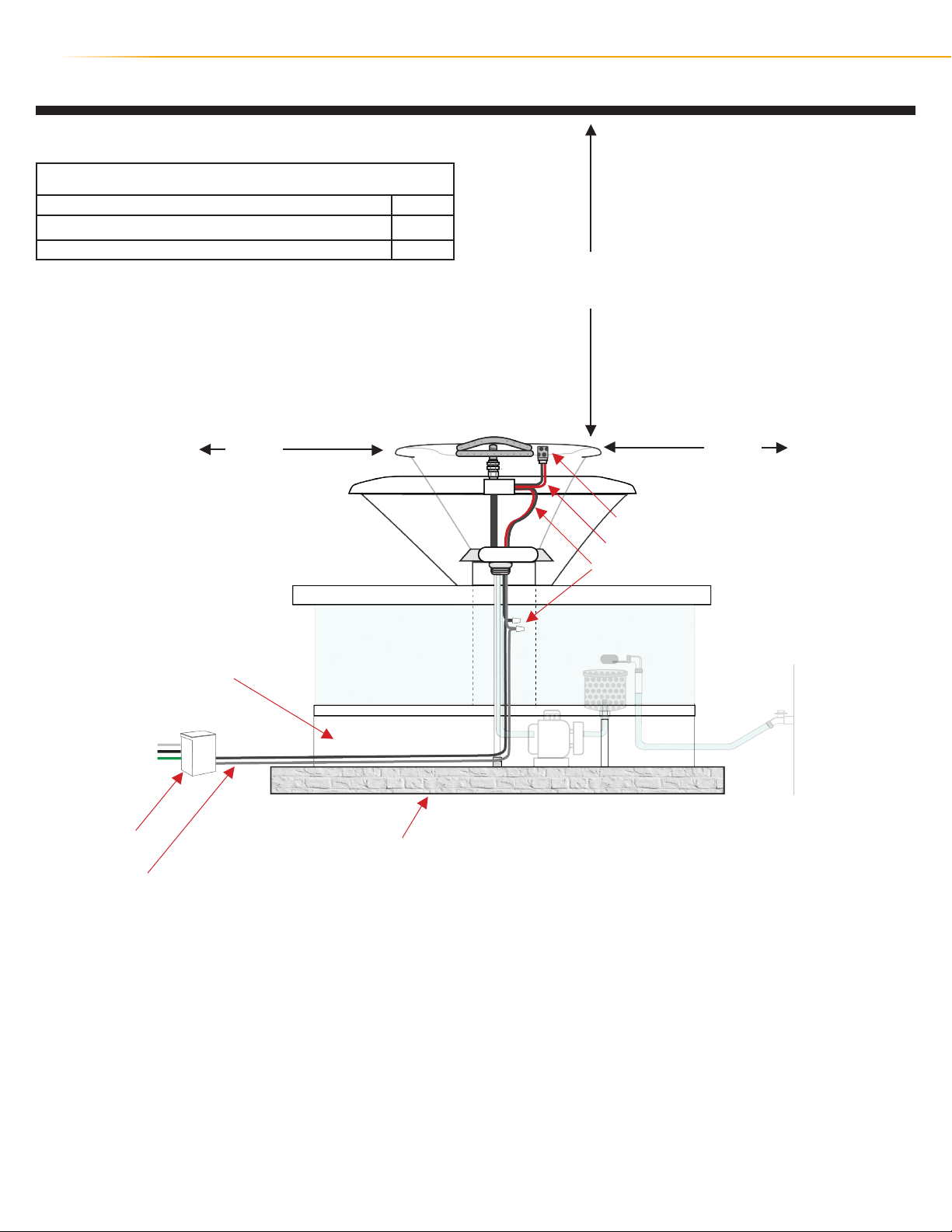
ASSEMBLY |Fire Feature Installation
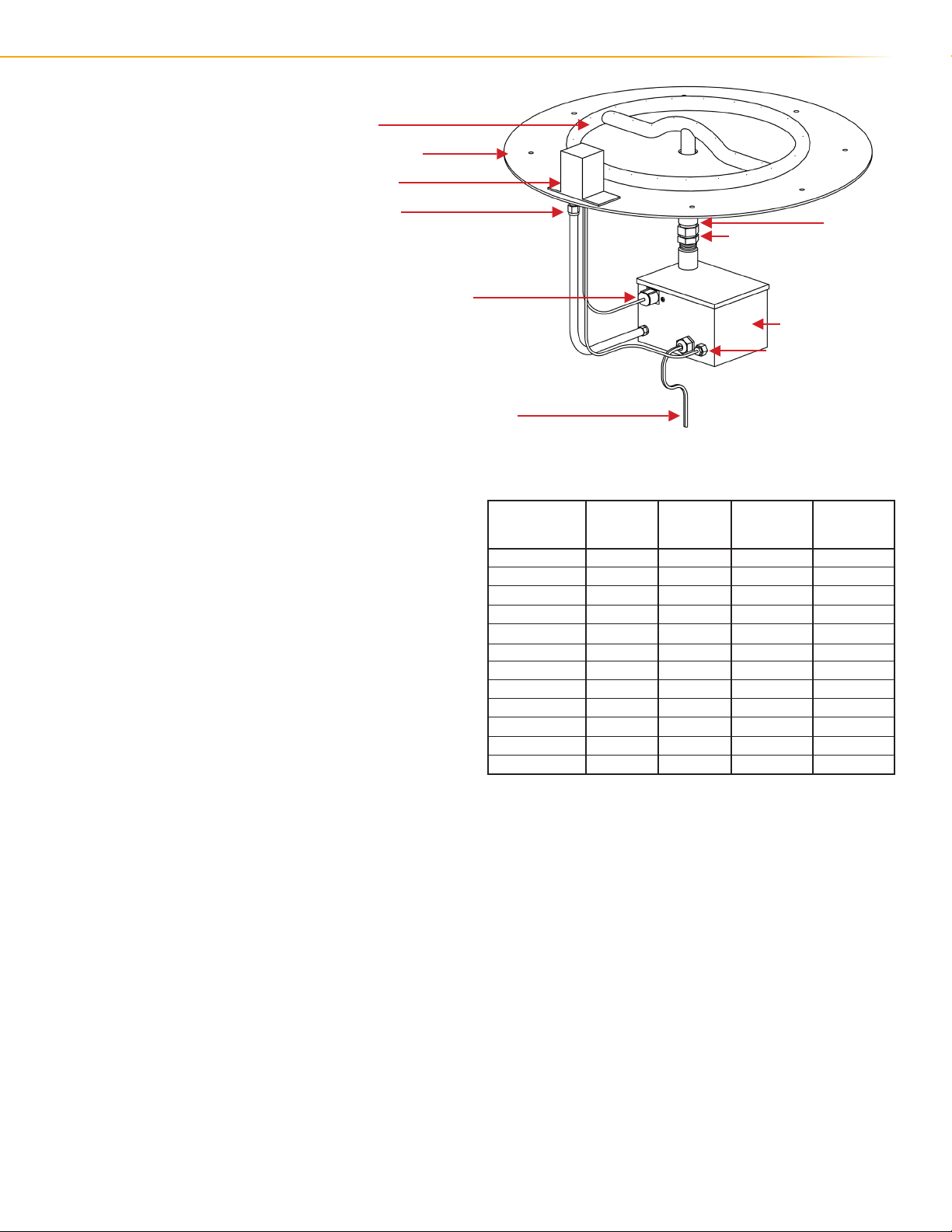
BURNER
Pan
Pilot
Gas Lead
Electrical Lead
Low Voltage Leads
Low Voltage Electronic Box
Thermopile Connection
Orice
Coupling
ELECTRICAL REQUIR-
MENTS:
NOTE: The Electronic Box is can only
be operated using 12 Volts.
DO NOT attempt to power the
Electronic Box using 110 Volts, it will
damage the internal components.
RUNNING GAS LINE:
Installing a gas piping below your re feature is
recommended.
In order to ensure that gas ows smoothlky and
eciently through a system, it is important to
minimize pressure drop.
Reduce the length of the gas piping and the
amount of elbows used. This will improve gas ow
& better overall system
performance.
120 VAC PRIMARY INPUT - 300 W OUTPUT
DISTANCE
FEET
5FT
10FT
20FT
30FT
40FT
50FT
60FT
70FT
80FT
90FT
100FT
110FT
12VAC
12VAC
12VAC
12VAC
13VAC
13VAC
13VAC
13VAC
13VAC
14VAC
14VAC
14VAC
12VAC
12VAC
12VAC
13VAC
13VAC
13VAC
14VAC
14VAC
14VAC
12VAC
12VAC
13VAC
13VAC
14VAC
14VAC
12VAC
13VAC
13VAC
14VAC
6AWG 8AWG 10AWG 12AWG
12 THE OUTDOOR PLUS | Self-Contained Unit Installation Manual
ASSEMBLY |Enclosure Cleareance
96”
48”
48”
Non-Combustible Flooring
Electrical Leads
Control Panel
Piolt
Pilot Connections
Electrical Leads
Cross Ventilation on
Opposite Side. Fire & Water
Fountain already comes
equipped with 360 degrees
of ventilation.
CLEARANCE AROUND FIRE PIT
Under Valve Box when applicable for drainage
Sides Surrounding Fire Pit From Structure or Combustibles
Overhead Clearance above Product
2”
48”
96”
13
ASSEMBLY |Water Feature Installation
WARNING
Never lift the unit by the Bowl, Tower, or Ring. This will damage the unit.
CAUTION
Before connecting the water system, ensure that the fountain is completely dry and free of
debris. Failure to do so can result in clogging or damage to the fountain’s components
IMPORTANT
WARRANTY REQUIRMENTS: The Fire & Water Fountain must be constructed on a stable surface.
IMPORTANT
WARRANTY REQUIRMENTS: Adequate drainage is essential to prevent damage to surrounding
surfaces in your chosen location. Please note that The Outdoor Plus does not provide a warranty
against drips or leaks and assumes no responsibility for any damages. As the installer, it is your
responsibility to ensure that there is sucient drainage to enable maintenance, repair,
winterization, or potential leaks from the water basin.
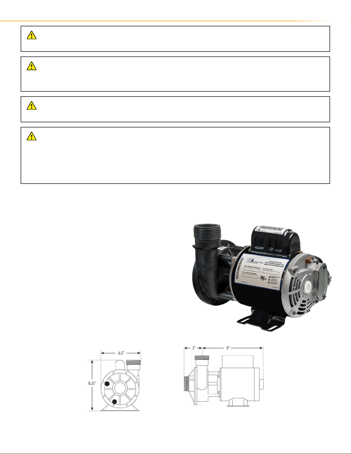
INSTALLING THE WATER FEATURE:
1. Install the pump, place it on a level surface below the water
level. For future maintenance, it is recommended to install
shut-o valves on both the inlet and outlet of the pump. The
installation area should have sucient oor drainage and the
pump should be protected from excessive moisture. Ensure
that there is enough access area to service both the pump and
plumbing.
NOTE: Hand Tighten Unions Only!
DO NOT use a wrench or any adhesives or solvents!
DO NOT use wrong sealant. Use Teon or approved sealing
compounds for plastic. Wrong sealants can damage plastic.
New installations need plumbing inspection. City water pressure
is used for this test. Pressure should not exceed 40 PSI. Remove
air from the system when pump and lter are under pressure.
Be careful during the pressure test to avoid injury and voided
warranties.
14 THE OUTDOOR PLUS | Self-Contained Unit Installation Manual
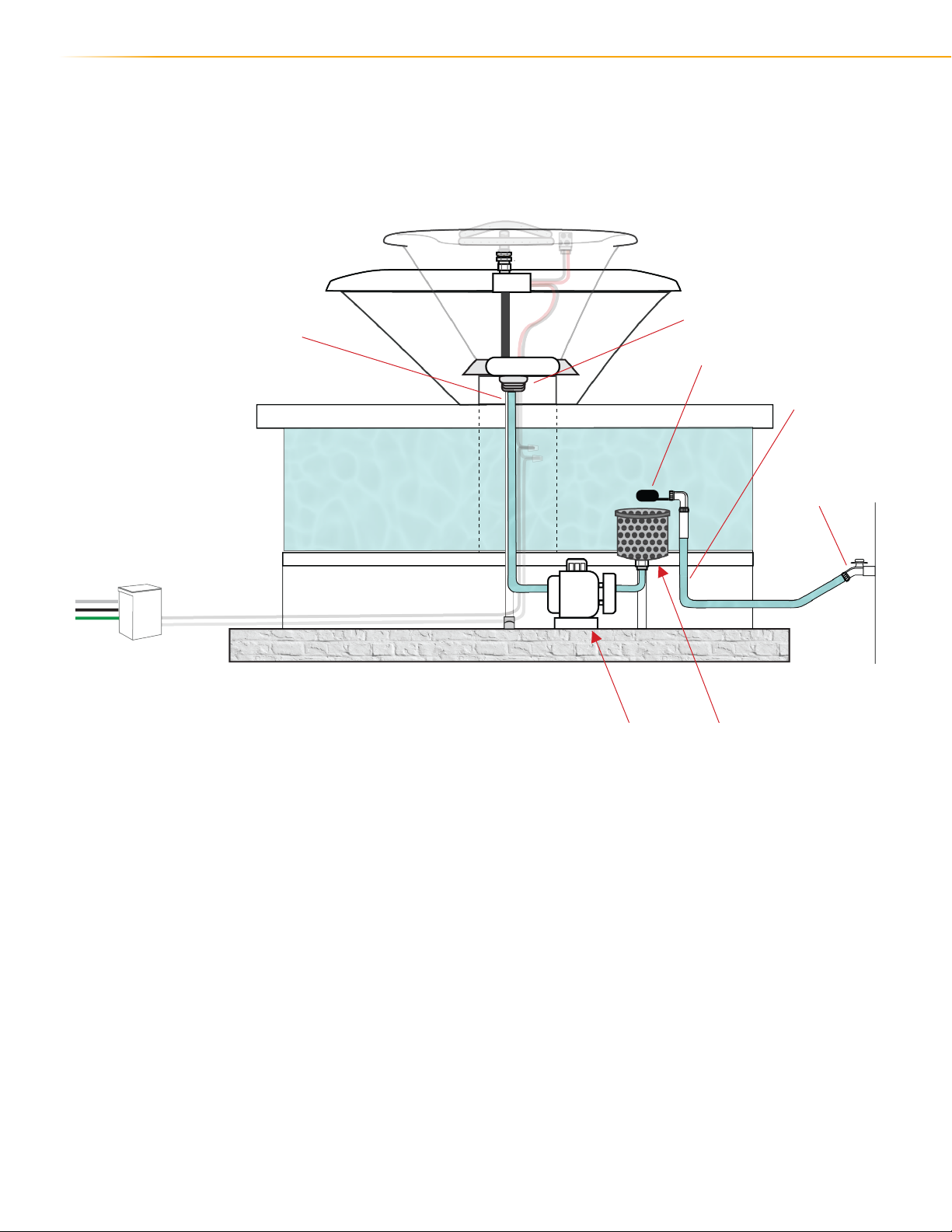
ASSEMBLY |Water Feature Installation
Union Nut
Pump Hose
24/7 Water Pump Clean Water
Filter System
Auto-Fill
Auto-Fill Hose
House Water System

15
ASSEMBLY |Leveling Your Fire & Water Feature
IMPORTANCE OF LEVELING:
It is important to your Fire & Water Fountain. When the fountain is not level, it can aect the overall appearance and
functionality of the fountain. A sloping fountain can cause water to overow in on area, leading to an unbalanced
appearance.
You will need the following tools:
Before starting any type of leveling - make sure your water and gas supply are Turned O.
1. Start by removing any debris or dirt from the area you will be working on.
2. Place the fountain on a leveled area and check its balance using the Spirit Level. Check both horizontal and verti-
cally levels to ensure the fountain is level in both directions. If needed follow steps 3-9, to safely add shims.
Adding Shims
3. If the fountain is not leveled. You can use sometype of shim, wooden or rubber shims work well. Start by remov-
ing any
material under its base. Adjust the shims accordinly. Until the fountain gets leveled.
4. Once the fountain is level, check it again using the level tool to ensure that it is still balanced. Adjust as needed.
1. A Spirit Level 2. Shims 3. Measuring Tape 4. Rubber Mallet
WARNING
Do not attempt to level the fountain by yourself. Always have at least two people present to avoid
accidents and injury.
WARNING
Never attempt to level the fountain while it is in operation. Turn o all electrical and gas
connections before beginning the leveling process.
Auto-Fill Hose
House Water System

16 THE OUTDOOR PLUS | Self-Contained Unit Installation Manual
ASSEMBLY |Electrical Wiring Schematic
ELECTRICAL SCHEMATIC OVERVIEW:
The Electrical Wiring Schematic is an essential component of the Fire & Water Fountain installation process. The
schematic diagram illustrates the electrical connection and wiring for the Fire & Water Fountain, Lighting, and Igni-
tion System.
It is important to note that only a qualied and licensed electrician should carry out the electrical wiring of the Fire &
Water Fountain. They should have a good understanding of electrical systems and be able to read and interpret the
schematic diagram.
Before starting the electrical wiring, the installer should ensure that the electrical power to the fountain is turned
o. The wiring schematic is designed to ensure that the fountain operates safely and eciently. It is crucial to note
that any modications or deviations from the wiring instructions provided in the manual could also void the manu-
facturer’s warranty.
By following the wiring instructions provided, the installer can ensure that the fountain functions correctly and
meets all necessary safety requirements. This can help to avoid potential hazards, including electric shock or other
safety risks.
DANGER
Electrical shock hazard. Only a qualied and licensed electrician should carry out the electrical
wiring of the Fire & Water Fountain.
WARNING
Do not attempt to perform any electrical work without disconnecting power to the fountain rst.
Failure to do so can result in serious injury or death.
CAUTION
Modications or deviations from the wiring instructions provided in the manual could void the
manufacturer’s warranty and create serious safety hazards. Always follow the wiring instructions
carefully to ensure safe and proper operation of the fountain.

17
AUTOMATION SYSTEM
This can be:
Transformer, Dial Timer, E-Stop,
Bluetooth System.
Power Switch:
Control Remote or Commercial
Light Switch
Low Voltage Leads
12 Volts
110V Leads
LOW VOLTAGE
IGNITION SYSTEM

18 THE OUTDOOR PLUS | Self-Contained Unit Installation Manual
START-UP & TESTING|Gas Leak Test
PERFORM A GAS LEAK TEST:
It is important to ensure that you conduct a gas leak test before starting your Fire Feature on your Self-Contained Unit.
Here a step-by-step guide on how to conduct a gas leak test on your unit:
Step 1: Turn o the Gas Supply
The rst step is to turn o the gas supply to the re and water fountain. It’s important to make sure that the gas supply is
completely turned o before proceeding to the next step.
Step 2: Make The Solution
Grab an empty container that can hold enough atleast 8oz of water. Apply inside the container both water and liquid soap. 1:1
Step 3: Apply The Solution
Using the solution (Soap & Water), apply a small amount to the connection point of the gas line. The solution will bubble up if
there is a gas leak present.
Step 4: Check for Bubbles
If bubbles are present, this indicates a gas leak. If no bubbles are present, the connection is secure and there is no gas leak.
Step 5: Turn on the Gas Supply
Finally, turn on the gas supply to the re and water fountain. Check for any gas leaks at the connection point once more. If no
19
START-UP & TESTING|Start-Up
OPERATING YOUR FIRE & WATER FOUNTAIN:
Before operating your re feature ensure there is not any debris, leaves, or other combustible material. It is
important to keep safety in mind, here are some quick tips for safely operating your re & water fountain:
1. Keep the area clear of any combustible materials.
2. Never leave the Self-Contained Unit unattended
3. Never use other ammable materials such as gasoline or lighter uid to start the re.
4. Ensure there is a always a re extinguisher nearby in case of an emergency.
5. Keep children and pets away from the fountain when in use.
6. Regularly inspect and maintain the fountain and its components, including the gas line and electrical wiring, to
ensure they are in good working condition.
POOL AUTOMATION (Start-Up):
If you are using a Pool Automation System to turn on your Fire Feature follow these steps:
1. Ensure your pool automation system is compatible with our Fire Feature, most automation system are
compatible with our Fire Features.
2. Once you have properly connected the pool automation to your re feature, access the automation system’s
programming mode, and select re feature as one of the controllable devices. Depending on your automation
system you might need to put more information about the re feature like BTU output. Read your automation
system’s manual to guide correctly install the Fire Feature Unit.
3. Once the re feature has been added, you can schedule the self-contained unit to turn on to a set schedule, when
an event occurs, or you can manually turn each feature on.
WARNING
Use of the pool automation system can be dangerous and result in injury or death if not used
properly. Before using the pool automation system, carefully read and follow all manufacturer
instructions and safety guidelines.
WARNING
Do not use the pool automation system if you are not familiar with its operation, or if you are not
able to operate it safely. Always keep the system out of reach of children and pets.
WARNING
If you detect any issues with the pool automation system, including malfunctioning or abnormal
behavior, immediately discontinue use and contact a qualied technician for assistance.
20 THE OUTDOOR PLUS | Self-Contained Unit Installation Manual
START-UP & TESTING|Start-Up
REMOTE CONTROL (Start-Up):
Always follow the manufacturer’s instructions and safety guidelines when operating any kind of re & water
features. If you have any concerns or issues with the operation of your re & water feature or remote control
system, consult the manufacturer or a qualied technician for assistance. Follow these steps to properly pair your
control remote unit.
1. Make sure that the gas and water supply to the re & water feature are turned on and functioning properly. This
will ensure that the feature is able to operate once it is turned on.
2. Turn on the Bluetooth system that is connected to the low voltage electronic box. Make sure that the system is
paired with the remote control and that both devices are functioning properly.
3. Locate the button or switch on the remote control that is used to activate the re & water feature. Depending on
the specic remote control and system, this may be labeled or identied as the control for the feature.
4. Press the button or ip the switch to activate the re & water feature. Depending on the specic system, you may
need to hold the button down for a few seconds until the feature is fully activated and functioning.
5. Once the re & water feature is activated, monitor it closely to ensure that it is operating safely and correctly.
Make sure that the gas and water supply remain connected and functioning properly, and that there are no leaks or
other issues.
6. When you are nished using the re & water feature, use the remote control to turn it o. Make sure that the
WARNING
Do not use the remote control if it is damaged or not functioning properly.
WARNING
Keep the remote control out of reach of children and pets
WARNING
Do not allow the remote control to become wet or submerged in water.
WARNING
Make sure that the remote control is paired properly with the Bluetooth system and that both
devices are functioning properly before use.
Table of contents
Popular Outdoor Fountain manuals by other brands

Elkay
Elkay Soft Sides EDFP210FP B Series Installation, care & use manual

Angelo Decor
Angelo Decor Countryside Cascade AD97040 quick start guide

Halsey Taylor
Halsey Taylor OVL-EBP owner's manual

Campania International
Campania International FT-258 Assembly instructions

Blue Thumb
Blue Thumb Fountain Vase installation manual

Campania International
Campania International Meridian FT-325 quick start guide


