The Tile Doctor WTS950LN User manual
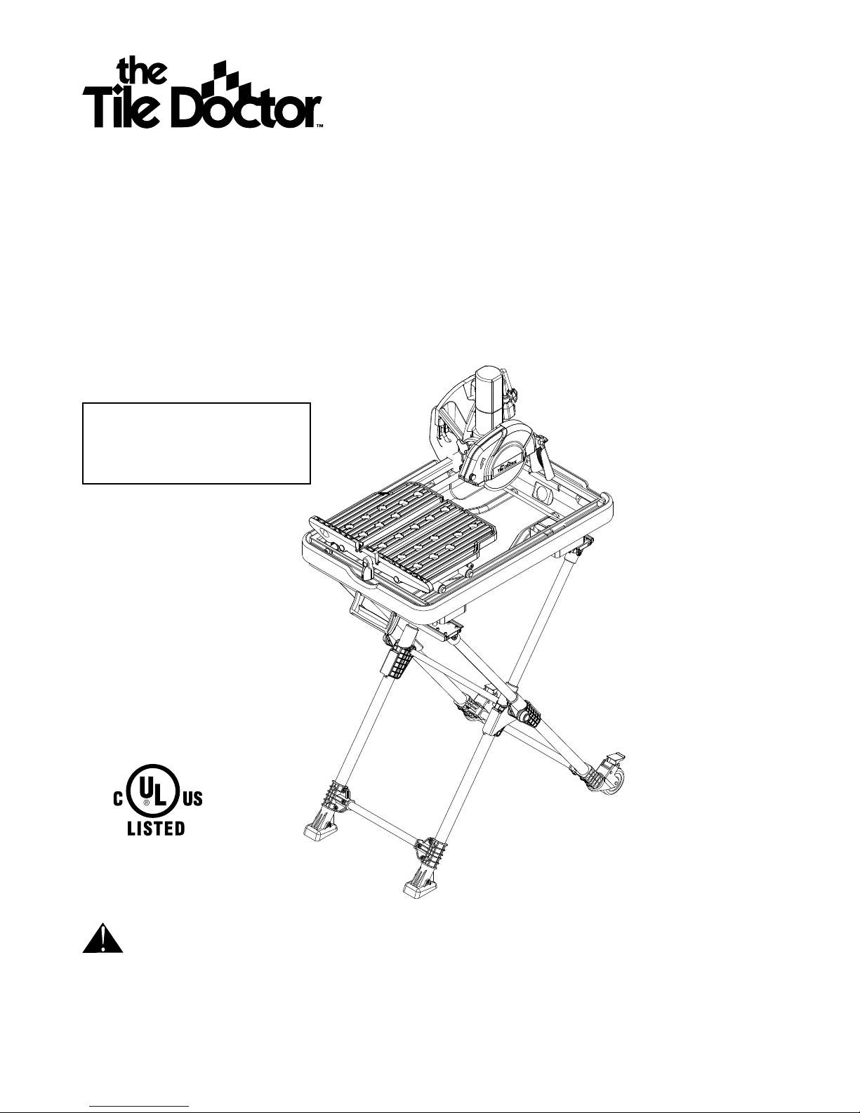
INSTRUCTION MANUAL
7 “
WE
T
TILE/ST
ONE
S
A
W
WITH
LASER AND
S
T
AND
PLEASE KEEP THIS
MANUAL FOR
FUTURE REFERENCE
CAUTION:
Read, understand, and follow all safety rules and instructions before using
this tool. These safety instructions should be followed at all times. Failure to follow these safety
instructions could result in injury to you or to others. Also, failure to read and follow these
instructions may cause damage to your equipment.
87VA
87VA CALL CUSTOMER
SERVICE
(TOLL
FREE)
1-877-845-3363

2.
3.
1 YEAR LIMITED WARRANTY
If within one year from date of purchase, this Tile Doctor product fails due to a defect in materials or workmanship, call the Ser-
vice Center at 1-877-845-3363. Please have a copy of the original receipt for all warranty claims.This warranty excludes inciden-
tal or consequential damages and failures due to misuse, abuse or normal wear and tear.This warranty gives you specific rights,
and you may also have other rights, which vary, from state to state. Please call 1-877-845-3363 for details.
TABLE OF CONTENTS
SECTION PAGE
Warranty, Technical specifications……………..………………2
General safety instructions…………………………..…………2
Specific safety instructions ……………….....…………………5
Saw features………………………………………………..……6
Unpacking major components……………..……………..……7
Unpacking accessories…………………………………..…..…7
Assembly……………………………………………….…..........8
Operation………………………………………………..….…..11
Maintenance…………………………………………….....…..13
Trouble shooting………………………………......……….…..14
Exploded drawing and parts list……………………….….…..15
TECHNICAL SPECIFICATIONS
7 “WET TILE/STONE SAW WITH LASER AND STAND
Power supply ...................................................... 120V ~, 60Hz
Motor capacity ...................................................................... 8A
No-load speed ......................................................... 7000 RPM
Diamond blade size ............................ 7 ”X 5/64”X 5/8”(Bore)
Maximum depth of cut at 0° ............................................ 2-1/4”
Maximum depth of cut at 45° .............................................. 1”
Tilting range .....................................................................0°,45°
Size of water tray ........................ 28-3/8”X 18-1/2 ”X 3-15/16”
Maximum rip cut ................................................................... 22”
Maximum square tile of diagonal cut ...................................16”
GENERAL SAFETY INSTRUCTIONS
WARNING: Some dust created by using power
tools contains chemicals known to the state of
California to cause cancer and birth defects or other
reproductive harm.
Safety is a combination of using common sense, staying
alert, and knowing how your tile saw works. Read this
manual to understand this tile saw and how to use it safely.
SAFETY SYMBOLS
The purpose of safety symbols is to attract your attention
to possible dangers. The safety symbols and the
explanations that accompany them deserve your careful
attention and understanding. The safety warnings DO
NOT, by themselves, eliminate any danger. They are no
substitutes for proper accident-prevention measures.
DANGER: Someone will be seriously injured or
killed if the safety information is not followed.
WARNING: Someone could be seriously injured or
killed if the safety information is not followed.
CAUTION: Someone may be injured if the safety
information is not followed.
DAMAGE PREVENTION AND INFORMATION
MESSAGES
These inform the user of import information and/or
instructions that could lead to equipment or other
property damage if they are not followed. Each message
is preceded by the word”NOTE,” as in the example below:
NOTE: Equipment and/or property damage may result if
these instructions are not followed.
WORK-AREA SAFETY
• KEEP THE WORK AREA CLEAN AND WELL LIT.
Cluttered benches and dark areas invite accidents.
• DON’T USE IN A DANGEROUS ENVIRONMENT. Don’t
use power tools in damp or wet locations or expose them
to rain. Don’t operate power tools in potentially explosive
environments, such as in the presence of flammable
liquids, gases, or dust. Power tools create sparks, which
may ignite the dust or fumes.
• OPERATE THE TOOL IN WELL-VENTILATED AREAS,
and provide proper dust removal. Dust generated from
some materials can be hazardous to your health. Use
dust-collection systems whenever possible.
• KEEP CHILDREN AND BYSTANDERS AWAY. All
visitors should be kept a safe distance away from the
work area.
• USE THE RIGHT TOOL. Don’t force a tool or attachment
to do a job for which it was not designed.
• MAKE THE WORKSHOP CHILD-PROOF with padlocks,
master switches, or by removing starter keys.
ELECTRICAL SAFETY
WARNING! To reduce the risk of electrocution, keep
all connections dry and off the ground. Do not touch
plug with wet hands.
• VOLTAGE: Before plugging in the tool, make sure that
the outlet voltage is within the voltage marked on the
tool’s data plate.
• DO NOT USE “AC ONLY” RATED TOOLS WITH A DC
POWER SUPPLY.
• DO NOT EXPOSE POWER TOOLS TO RAIN OR WET
CONDITIONS. Water entering a power tool will increase
the risk of electric shock.
• If operating the power tool in damp locations is
unavoidable, always use a Ground Fault Circuit
Interrupter to supply power to your tool. Always wear
electrician's rubber gloves and footwear in damp
conditions.
• DO NOT ABUSE THE CORD. Never use the cord to
carry the tools or to pull the plug from the outlet. Keep
the cord away from heat, oil, sharp edges, or moving
parts. Replace damaged cords immediately. Damaged
cords increase the risk of electric shock.
• USE THE PROPER EXTENSION CORD.
Extension Cords
Use only extension cords that are intended for outdoor
use. These extension cords are identified by a marking
“Acceptable for use with outdoor appliances, store indoors
while not in use.”
Use only extension cords having an electrical rating
equal to or greater than the rating of the product. Do not
use damaged extension cords. Examine the extension
cord before using, and replace it if it is damaged. Do not
abuse extension cords, and do not yank on any cord to
disconnect it. Keep the cord away from heat and sharp
edges. Always disconnect the extension cord from the
receptacle before disconnecting the product from the
extension cord.
•
Make sure that your extension cord is in good condition.
•
When using an extension cord, be sure to use one
heavy enough to carry the current your product will
draw. An Undersized cord will cause a drop in line
voltage resulting in loss of power and overheating.
•
Table 1 shows the correct size to use depending on
cord length and ampere rating. If in doubt, use the
next heavier gauge: the smaller the gauge number, the
heavier the cord.
•
When operating a power tool outdoors, ALWAYS use
an outdoor extension cord marked “W-A” or “W.” These
cords are rated for outdoor use and reduce the risk of
electric shock.
•
Use only 3-wire extension cords that have 3-prong
grounding plugs and 3-pole receptacles that accept the
tool’s plug.
Table 1
Ampere
rating
Volts Total length of cord in feet
120 V~
25ft. 50ft. 100ft. 150ft.
A. W. G.
0~6 18 16 16 14
6~10 18 16 14 12
10~12 16 16 14 12
12~16 14 12 not recommended
Ground Instruction
All grounded, cord-connected tools:
• In the event of a malfunction or breakdown, grounding
provides a path of least resistance for the electric current
to reduce the risk of electrical shock. This tool has an
electric cord with an equipment-grounding conductor
and a grounding plug. The plug must be plugged into a
matching outlet that is properly installed and grounded in
accordance with all local codes and ordinances.
• Do not modify the plug provided with this tool. If it will not
fit the outlet, have a properly grounded outlet installed by
a qualified electrician.
• Improper connection of the equipment-grounding
conductor can result in electric shock. The wire covered
with green insulation is the equipment-grounding
conductor. If repair or replacement of the electric cord or
plug is necessary, do not connect the green wire to a live
terminal.
• Check with a qualified electrician or service personnel if
you do not completely understand the grounding instruc-
tions, or if there is a question as to whether the tool is
properly grounded. Use only 3-wire extension cords that
have 3-prong grounding plugs and 3-pole receptacles
that accept the tool’s plug.
• Repair or replace a damaged or worn cord immediately.
Grounded, cord-connected tools intended for use on a
supply circuit having a nominal rating less than 150 Volts:
• This tool is intended for use on a circuit with a grounded
outlet (B, Fig. A). The tool has a grounding plug (A, Fig.
A).
• A temporary adapter (D, Fig. A) may be used to connect
this plug to a 2-pole receptacle (C, Fig. A), if a properly
Fig. A
(B)
(A)
(C)
(D)
Grounding Pin
Adaptor
Grounding Means
Adaptor Is Not Permitted In Canada
Metal
Screw
Cover Of
Grounded
Outlet Box
4.
5.
grounded outlet is not available. The green-colored tab
extending from the adapter must be connected to a per-
manent ground, such as a properly grounded outlet box.
The temporary adapter should be used only until a quali-
fied electrician can install a properly grounded outlet.
Permanently connected tools
This tool can be permanently connected to a grounded,
metal, wiring system or to a system that has an equipment-
grounding conductor.
Ground-fault circuit interrupter (GFCI) protection should be
provided on the circuit or outlet to be used for the tile saw.
Receptacles are available having built-in GFCI protection
and may be used for this measure of safety.
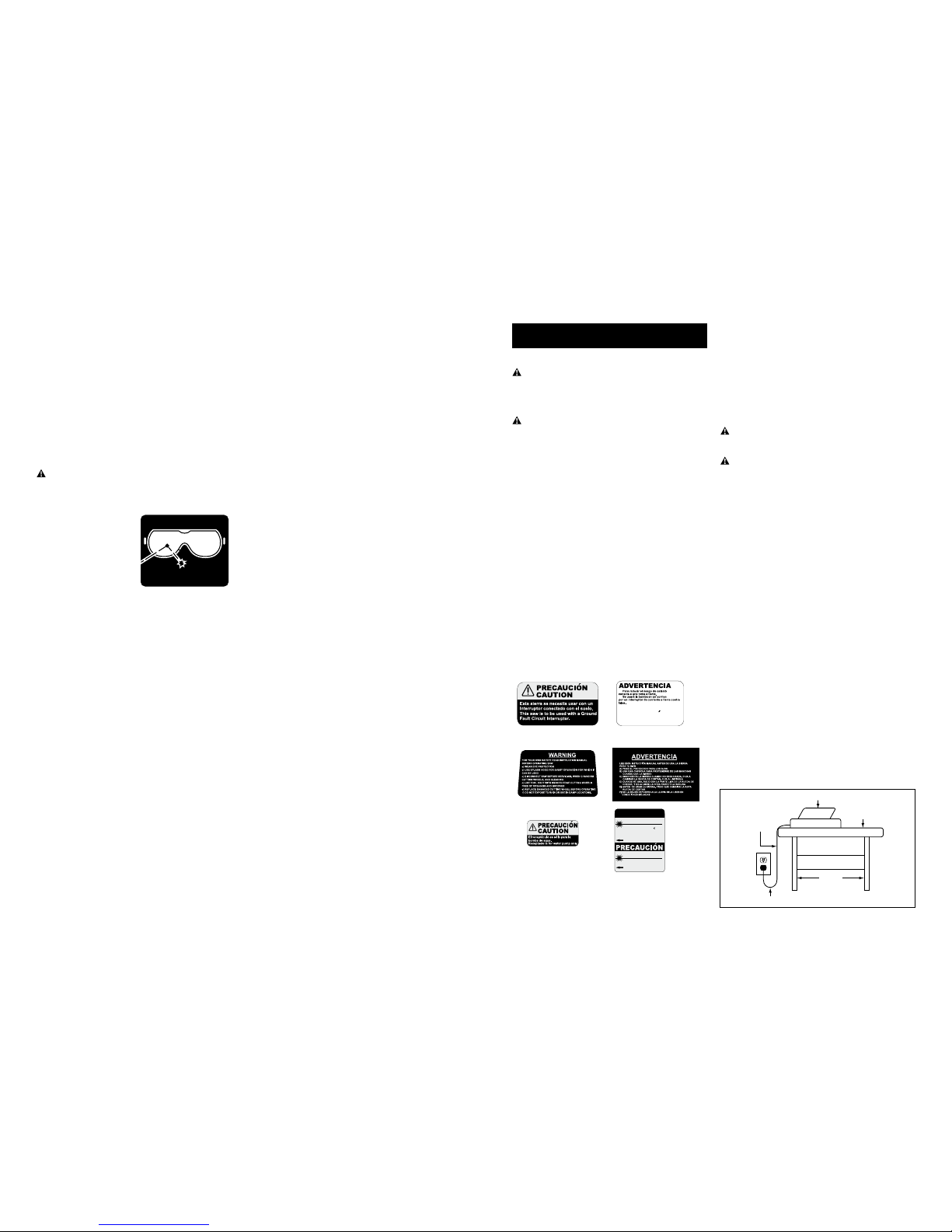
PERSONAL SAFETY
WARNING: The operation of any power tool can
result in foreign objects being thrown into your
eyes, which can result in severe eye damage. Before
beginning power-tool operation, always wear safety
goggles or safety glasses
with side shields, and a full-
face shield when needed.
We recommend Wide Vision
Safety Mask for use over
eyeglasses or standard
safety glasses with shields.
Always use eye protection,
which is marked to comply
with ANSI Z87.1
• STAY ALERT, WATCH WHATYOU ARE DOING, and
USE COMMON SENSE when operating a power tool.
• DO NOT use the tool while tired or under the influence of
drugs, alcohol, or medication.
• WEAR PROPER APPAREL. Do not wear loose clothing,
gloves, neckties, rings, bracelets, or other jewelry.
Pull back and secure long hair. Non-slip footwear is
recommended.
• KEEP YOUR HAIR, CLOTHING, AND GLOVES AWAY
FROM MOVING PARTS.
• REMOVE ADJUSTING KEYS OR WRENCHES. Form
a habit of checking to see that keys and adjusting
wrenches are removed from the tool before turning it on.
• ALWAYS USE SAFETY GLASSES. Everyday glasses
may have impact-resistant lenses, but they are NOT
safety glasses.
• USE A DUST OR FACE MASK, if the operation is dusty.
• WEAR HEARING PROTECTION to help prevent
hearing loss.
• NEVER TOUCH THE PINS OF THE ELECTRICAL
PLUG while inserting it into or removing it from an
electrical socket.
• NEVER STAND ON TOOL. Serious injury could occur
if the tool is tipped, or if the cutting tool is unintentionally
contacted.
TOOL SAFETY
• KEEP ALL GUARDS IN PLACE and in working order.
• AVOID ACCIDENTAL STARTING. Be sure the switch is in
the “Off” position before plugging the tool into an electrical
outlet.
FORESIGHT IS BETTER
THAN NO SIGHT
WEAR YOUR
SAFETY GLASSES
• DO NOT CARRY TOOLS WITH YOUR FINGER ON THE
SWITCH.
• DO NOT OVER REACH. Keep proper footing and balance
at all times.
• DO NOT FORCE THE TOOL. Use the correct tool and
blade for your application. The correct tool and blade will
do the job better and more safely when used at the rate
for which it is designed.
• DO NOT USE TOOL IF THE SWITCH DOES NOT TURN
IT “ON” OR “OFF.” Any tool that cannot be controlled
with the switch is dangerous and must be repaired.
• DISCONNECT THE TOOL before servicing, when
changing accessories (such as cutting blades), or storing
the tool.
• STORE IDLE TOOLS OUT OF THE REACH OF
CHILDREN and other untrained people.
• NEVER LEAVE THE TOOL RUNNING UNATTENDED;
turn the power off. Don’t leave the tool until it comes to a
complete stop.
• ALWAYS MAINTAIN TOOLS WITH CARE. Keep cutting
tools sharp and clean. Properly maintained tools with
sharp cutting edges are less likely to bind and are easier to
control. Follow all instructions for lubricating and changing
accessories.
• CHECK FOR DAMAGED PARTS. Before further use of
the tool, a guard or other part that is damaged should be
carefully checked to determine that it will operate properly
and perform its intended function. Check for alignment of
moving parts, binding of moving parts, mounting, and any
other conditions that may affect its operation. A guard or
other part that is damaged should be properly repaired or
replaced.
• USE RECOMMENDED ACCESSORIES. Consult the
product manual for recommended accessories. The use
of improper accessories may increase the risk of personal
injury.
SERVICE SAFETY
• If any part of this we-tile/stone saw is missing or should
break, bend, or fail in any way; or should any electrical
component fail to perform properly: ALWAYS shut off the
power switch and remove the plug from the power source,
and have the missing, damaged, or failed part replaced
BEFORE resuming operation.
• When servicing a tool, ALWAYS use only identical
replacement parts. Follow instructions in the Maintenance
Section of this manual. Use of unauthorized parts or
failure to follow Maintenance Instructions may create a
risk of electric shock or injury.
SPECIFIC SAFETY INSTRUCTIONS
FOR WET TILE/STONE SAW
SAFETY INSTRUCTIONS FOR WET TILE/STONE SAW
WARNING: BE SURE to read and understand all
instruction in this manual before using this Wet Tile/
Stone Saw with Laser Guide and Stand. Failure to
follow all instructions may result in electric shock, fire
and/or serious personal injury
WARNING: To reduce the risk of mistakes that
could cause serious, permanent injury, do not plug the
tile saw into an electrical receptacle until the following
steps have been satisfactorily completed:
• Completely assemble the saw (See “Assembly”
section).
• Learn the use and function of the ON-OFF switch,
blade guard, laser-adjustment-knob, overload protector,
spindle lock, depth-stop-adjustment knob, depth-
adjustment knob, bevel-cut-adjustment knob, universal
guide etc. (See “Getting to Know Your Tile Saw” section).
• Review and understand all safety instructions and
operating procedures in this manual.
• Review the maintenance methods for this saw (See
“Maintaining Your Saw” section).
• Never put your fingers or hands in the path of the saw
blade or other cutting tool.
• Never reach behind the cutting tool with either hand for
any reason. Do not reach behind the blade to hold down
the work piece, support the work piece, remove scraps,
or for any other reason.
• Never use a hand position where a sudden slip could
cause the fingers or the hand to move into a saw blade.
• Find and read all the warning labels found on the tool
(shown below).
The labels on your tool may include the following symbols.
V.................................... Volts
A.................................... Amperes
Hz.................................. Hertz
W................................... Watts
min................................ Minutes
~
.................................... Alternating current
no.................................. No-load speed
RPM.............................. Revolutions or Strokes per minute
................................. Indicates danger, warning or
caution. It means attention! Your
safety is involved.
WARNING! Use of this tool can generate dust-
containing chemicals known to the state of California
to cause cancer, birth defects, or other reproductive
harm. Some examples of these chemicals are:
• Lead from lead-based paints.
• Crystalline silica from bricks, cement, and other
masonry products.
• Arsenic and chromium from chemically treated lumber.
Your risk from these exposures varies, depending
upon how often do this type of work.To reduce your
exposure to these chemicals:
• Work in a well-ventilated area.
• Work with approved safety equipment, such as
those dust masks that are specially designed to filter
out microscopic particles.
Avoid prolonged contact with dust from power
sanding, sawing, grinding, drilling, and other
construction activities. Wear protective clothing and
wash exposed areas with soap and water.
Allowing dust to get into your mouth or eyes or to lie on
the skin may promote absorption of harmful chemicals.
Use of accessories that are not recommended for use
with this tool may create hazardous conditions.
• DIRECTION OF FEED: Always feed work into the blade
against the rotational direction of the blade.
• LET THE BLADE COME TO A COMPLETE STOP
before removing any jammed or off-cut material from
around the blade area.”
• POSITION OF TILE SAW: To avoid the possibility of the
appliance plug or receptacle getting wet, position the tile
saw to one side of a wall-mounted receptacle.The user
should arrange a “drip loop” in the cord connecting the
saw to a receptacle. (Fig. B)
Fig. B Tile Saw
Power Supply
Cord
Drip Loop
Water Tray
Tile Saw
Support
Esta bomba no se hainvestigado para el uso
en lapiscinani áreas marinas.
Utilice sólo con aguadulce.
PRECAUCION
1.
2.
3.
CAUTION
LASER RADIATION-
DO NOT STARE INTO BEAM
AVOID EXPOSURE--Laser radiation is
emitted through this aperture
Wavelength:635nm
Complies with 21 CFR 1040.10 and 1040.11
Max output: 2.5mW
Class IIIa Laser Product
RADIACION LASER-
NO MIRE FIJAMENTE EL RAYOLÁ SER
EVITE LA EXPOSICION-RADIACION LASER.
EVITE EXPOSICION DIRECTADE LOS OJOS

6.
7.
The “drip loop” is a section of the cord that hangs below the
level of the receptacle or below the connector, if an exten-
sion cord is used, to keep the water that travels along the
cord from coming into contact with the receptacle. (Fig. B)
If the plug or receptacle does get wet, DON’T unplug the
cord. Disconnect the fuse or circuit breaker that supplies
power to the tool. Then unplug the tool and examine the
receptacle for water. Do not use the receptacle until it is
completely dry.
SAFETY INSTRUCTIONS FOR LASER
This saw has a built-in laser light. The laser is class IIIa
and emits output power of a maximum
2.5mW and 635nm wavelengths. The laser doesn’t
normally present an optical hazard.
CAUTION: The following label is on
your saw. It indicates where the laser
light is emitted by the saw.
CAUTION: Avoid exposure.
Laser radiation is emitted through
this aperture.
CAUTION: The use of controls or
adjustments or the performance of
procedures other than those directed in this manual
may result in hazardous radiation exposure.
WARNING: Laser radiation Avoid direct eye
exposure. Do not stare into the beam.Turn the laser on
only when the tool is operated.
WARNING: Be sure to read and understand all
instructions. Always follow the following safety rules
when using this saw:
• NEVER aim the beam at any person or at any object
other than the work piece.
• DO NOT look directly into the laser-beam output
aperture during operation. The laser beam can be
harmful to the eyes.
• ALWAYS keep the laser out of the reach of children.
The laser on the saw is not a toy.
• Using optical instruments with this product will
increase eye hazard.
DON’T ATTEMPT TO REPAIR OR DISASSEMBLE
the laser. If unqualified persons attempt to repair
this product, serious injury may result. Any repair
required on this laser product should be performed by
authorized service-center personnel.
SAW FEATURES
1. Stand handle
2. Water tray
3. Worktable
4. Table locking knob (Fig. 38)
5. Blade
6. Right-laser-beam adjustment knob (Fig. 35, Fig. 37)
7. Blade guard
8. Pump plug receptacle (Fig. 19)
9. Blade-guard wing nut (Fig. 21)
10. Anti-splash rubber guard
11. Water hose
12. Cutting-depth-adjustment knob (Fig. 11, Fig.48)
13. Motor/upper arm assembly (Fig. 10, Fig. 11)
14. 0°,45°bevel-cut adjustment knob (Fig. 47)
15. On/Off switch
16. Laser-battery-compartment release button (Fig. 32)
17. Laser-battery compartment (Fig.33)
18. Laser on/off switch
19. Left-laser-beam-adjustment knob (Fig. 35,Fig. 37)
20. Blade-guard locking knob (Fig. 20)
21. Lubrication port (Fig. 50)
22. Water pump
23. Lower arm assembly (Fig. 8, Fig. 9)
24. Parallel/angle guide
25. Spindle-lock button (Fig. 26)
WARNING! The use of any accessory or attachment
or performance of any operation with this tool other than
those recommend in this instruction manual may present a
risk personal injury.
UNPACKING MAJOR COMPONENTS
The contents of the carton are as follows:
Motor/upper arm
assembly (Includes blade
guard and water hose)
1 set
Frame assembly and
table(Includes slip bar)
1 set
Lower arm assembly 1 pc
Instruction manual 1 set
Accessories (see below) 1 set
UNPACKING ACCESSORIES
1. Telescoping, foldable
stand (Fig. 1, Fig. 2)
1 PC
2. Parallel/angle guide
(Fig. 44, Fig. 42)
1 PC
3. Saw blade 1 PC
4. Water pump (Fig. 5) 1 PC
5. Lower arm assembly
bolts with spring
washers (Fig. 9)
2
sets
6. Water tray 1 PC
7. Blade wrench (Fig. 27) 1 PC
8. Anti-splash rubber
guard (Includes
locking wing nut and
washer) (Fig. 31)
1 set
9. Lubricant (Fig. 50) 1 PC
10. Cutting-depth-
adjustment Knob
(Fig. 11, Fig. 48)
1 PC
11. Lower-arm-assembly
Hex wrench (Fig. .9)
1 PC
12. Lower-arm-assembly
cap (Fig.12)
1 PC
8
9
10
11
1
2
4
3
5
6
7
15
14 16
17
18
19
20
21
24
22
12
13
23
25
CAUTION
LASER RADIATION-
DO NOT STARE INTO BEAM
AVOID EXPOSURE--Laser radiation is
emitted through this aperture
Wavelength:635nm
Complies with 21 CFR 1040.10 and 1040.11
Max output: 2.5mW
Class IIIa Laser Product
RADIACION LASER-
NO MIRE FIJAMENTE EL RAYOLÁSER
EVITE LA EXPOSICION-RADIACION LASER.
EVITE EXPOSICION DIRECTADE LOS OJOS

8.
9.
INSTALL THE WATER PUMP
1. Attach the water pump in
the indent the tray wall, as
shown in Fig. 5.
2.
Place the water pump
power cord in the bottom of
the water tray as shown in
Fig. 5.
Note:The four suction cups
on the water pump should be
attached to the side of the water tray.
INSTALL THE FRAME ASSEMBLY AND TABLE
1. Align the water tray and the frame assembly and table
so that the plug hole in the water tray is on the same
side as the water drain opening in the frame assembly.
2. Place the frame assembly and table into the water tray
(Fig. 6.).
3. Locate the water plug on the frame and insert the water
plug into the drain hole (Fig. 7).
INSTALL THE MOTOR AND ARM ASSEMBLY
1. Place the lower-arm assembly onto the frame assembly
(Fig. 8).
2. Insert the bolts with the spring washers (supplied) into
the lower-arm assembly and thread them into the table
frame. The Lower-arm-assembly hex wrench supplied
can be used to assist in this process.
3. Firmly tighten both bolts (Fig. 9).
Fig. 1
Brake
Fig. 2
Ensure that you have checked the contents in the carton
with the Major Components and Accessories lists before
discarding carton or packing materials.
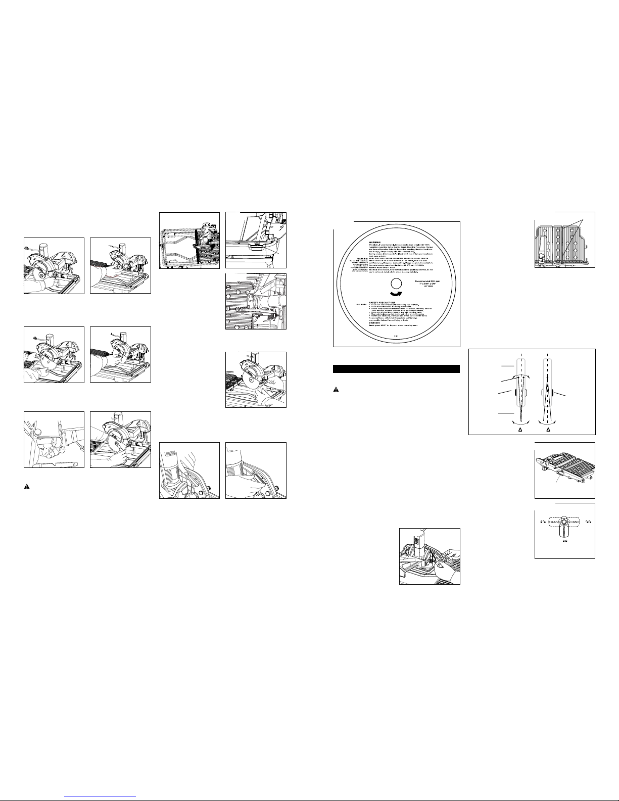
REPLACEMENT BLADES
We recommend the use of genuine Tile Doctor
replacement blades. Specify Cat. No.: HF180H Blade size:
7” x 5/64” x 5/8” Arbor size: 5/8”
A 7” blade may be used as a replacement.
ASSEMBLY
WARNING! For your own safety and protection, do
not attempt to operate this tile saw until it is completely
assembled and all components and accessories are
properly installed according to this instruction manual.
Read and understand the capability of the tile saw and the
hazards associated with its operation.
WARNING!
To avoid injury from unexpected starting
or electrical shock, the tool must remain unplugged
whenever your are performing an assembly, adjustments
or changing accessories.
WARNING! Read all instructions prior to use. Failure to
follow the safety rules listed in this manual and other basic
safety precautions may result in serious personal injury.
SET UP THE STAND
1. Pull one stand leg out of its sleeve, and then pull the
other stand leg out of its sleeve (Fig. 1).
2. Unfold the stand fully and make sure that it is firmly
seated (Fig. 2).
INSTALL THE WATER TRAY
1. Align the water tray on the stand as shown in Fig. 3: the
tray cutout and the stand wheels are on the same side.
2. The water tray will snap into place inside the four pins
on the stand.
3. Make sure that the water tray is securely seated in the
stand (Fig. 4).
Fig. 3
Cutout
Fig. 4
Cutout
Fig. 5
Fig. 6 Fig. 7
Fig. 8 Fig. 9
4. Slide the motor/upper-arm assembly onto the arm-
assembly shaft. The motor must be tilted down towards
the water tray to insure that the motor/upper-arm
assembly can slide fully into place (Fig. 10).
5.
Make sure that the motor/upper arm assembly fits snug
with the lower-arm assembly and that you are unable to
see the arm-assembly shaft.
6. Rotate the motor to the vertical position and secure the
motor/upper-arm assembly to the lower-arm assembly
with the depth-adjustment knob (Fig. 11).
7. Fit the lower-arm-assembly cap supplied onto the
lower-arm assembly (Fig. 12).
INSTALL THE WATER HOSE
1. Locate the water hose attached to the motor/upper arm
assembly. Route the water hose from the back of the
blade guard (where it is permanently affixed) to the water
pump, as illustrated by the thick black line in Fig. 13
2. Clips are located on the motor/upper-arm assembly
and lower-arm assembly to secure the water hose (Fig.
14, Fig. 15).
3. Insert the water hose through the hole on the lower-
arm assembly (Fig. 16), and then insert the water hose
into the pump’s intake hole (Fig. 17).
4. Route the pump’s electrical cord through the clip on
the back of the lower-arm assembly and plug it into the
shorter of the two electrical cords attached to the motor
(Fig. 18, Fig. 19).
INSTALL THE BLADE
1.
Loosen the wing nut on the blade guard (Fig. 21).
2. Loosen the locking knob on the front inside area of the
blade guard to release the blade guard (Fig. 20).
Fig. 13
Clips for water
hose of pump
Pump
Fig. 12a Fig. 12b
Fig. 10 Fig. 11
Fig. 14 Fig. 15
Fig. 16 Fig. 17
Fig. 18 Fig. 19
Fig. 20 Fig. 21
10.
11.
3.
Lift up the blade guard, and then tighten the wing nut
(Fig. 22).
4. Remove the motor-shaft nut and the outer flange. Only the
inner flange should remain on the blade shaft (Fig. 23).
5.
Fit the blade supplied onto the motor shaft (Fig. 24).
Caution: Make sure that the arrow on the blade points in
the same direction as the arrow marked on the blade guard.
6. Replace the outer flange and the motor-shaft nut (Fig. 25).
7. Press the spindle-lock button while tightening the
motor-shaft nut on the motor shaft with the wrench
supplied until the motor-shaft nut is screwed securely
(Fig. 26, Fig. 27).
8.
Lower
the blade guard and tighten the wing nut and the
locking knobs.
WARNING:
To reduce the risk of injury, use only
accessories rated at least 8000rpm.
ADJUST THE WORKTABLE
NOTE: It’s unnecessary to adjust the worktable before use,
because the positions of the worktable and the blade are
adjusted properly in the factory. If adjustment becomes
necessary, follow the worktable adjustment instructions
below.
1.
Push the worktable until one “∆” mark is under the blade.
2. Use a hex wrench(not provide) to loosen the two
nuts(M8 socket hexagon screw) (the other nut is at the
other end of the slip bar) to adjust the slip bar until the
blade is vertically aligned with the “
∆
” mark (Fig. 28, Fig.
29).
3. Push the worktable until another “
∆
” mark is under
the blade. Use a wrench to loosen the two nuts to adjust
Fig. 22 Fig. 23
Fig. 24 Fig. 25
Fig. 26 Fig. 27
the slip bar until the blade is
vertically aligned with the “
∆
”
mark (Fig. 30).
4. Follow steps 1 and 3 to
adjust the worktable three
times.
NOTE: Be sure to adjust the
worktable following steps 1
and 3 three times or more to
ensure that the worktable is
adjusted in the best position.
INSTALL THE ANTI-SPLASH RUBBER GUARD
Fit the rubber guard in place
and tighten it with the wing nut
and washer supplied (Fig. 31).
INSTALL THE LASER
BATTERIES
1. Press the gray button
to release the battery
compartment on the back
blade guard (Fig. 32).
2. Install two AAA batteries (not supplied) in the
compartment.
3. Push the battery compartment back into the blade
guard (Fig. 33).
Fig. 30
Fig. 31
Fig. 32 Fig. 33
WARNING ON BLADE
OPERATION
FILLING THE WATER TRAY
WARNING!
Lack of cooling water may damage the
saw blade. Never turn on the machine without enough
water in the tray or without plugging in the water pump.
To insure proper operation, check to make sure that the
pump is always fully immersed in the water tray.
SWITCH ON AND OFF
Connect the unit to a power source with the correct
voltage and frequency (120V, 60Hz).
1. To start the motor, turn the switch knob to the “ON”
position.
2. To stop the motor, turn the switch knob to the “OFF”
position.
NOTE: Providing the pump’s plug is inserted into the
pump plug receptacle on the motor (see Figs 18 and 19),
the pump will be turned on when the motor is turned on.
SAFETY FEATURE ON SWITCH
Pull out the switch knob (the yellow part) after the switch
has been set at the “OFF” position. This safety feature
prevents accidentally starting the machine.
CALIBRATING THE LASER LINE
1. Press the laser switch
button to turn on the laser,
press the button again to
turn off the laser. ALWAYS
shut off the laser light when
you are finished cutting
(Fig. 35).
2. Position the laser beam
across the two
“∆”
marks
engraved in the slot of the
Fig. 34
worktable and the table
fence by adjusting one or
both knobs on the sides of
blade guard. (Fig. 35, Fig.
36).
3.
If the laser line will not line
up with the two
“∆”
marks.
follow the instructions that
follow under Adjusting the
Angle and/or Alignment of
the Laser.
ADJUSTING THE ANGLE AND/OR ALIGNMENT
OF THE LASER
1. To adjust the alignment of the laser, turn the knob on
the left of the blade guard. Set the laser beam to align
with the
“∆”
marked on the slot on the table fence.
2. To adjust the angle of the laser beam, turn the knob
on the right side of the blade guard. Set laser beam to
align with the
“∆”
marked on the slot of the worktable.
3. For best result knobs should be adjusted
simultaneously.
EXTENDING THE TABLE
1. When the knob is on
the position A, both the
worktable and table fence
are locked and cannot move
on the slip bar (Fig. 39).
2. When the knob is on
the position B, the table
fence is locked, but it can
move on the slip bar with
worktable.(Fig. 39).
3. When the knob is on the
position C, both the worktable
and table fence are unlocked
and they can move on the
slip bar (Fig. 39).
Fig. 35
" "mark
Fig. 36 “∆” mark
Blade guard
Right adjustment
(ANGLE).
Left
adjustment
knob
(ALIGNMENT).
Laser beam
Laser (inside
blade guard)
knob
" " " "
Fig. 37
knob
Fig. 38
A( )
B( ) C( )
Fig. 39
Fig. 28 Fig. 29
Nut

12.
13.
PULLING THE TABLE FENCE
Put the locking knob on
Position C (Fig. 39), and then
pull the table fence out (Fig. 40).
CUTTING OPERATION
WARNING!
Turn the switch
knob to the “OFF” position
when adjusting the motor.
WARNING!
Do not attempt
to cut very small pieces. Avoid awkward hand positions
where a sudden slip could cause your hand or finger to
come in contact with the diamond blade. When cutting
any material, make sure that it is fully supported. Hold
workpiece firmly. Do not force the material into the
blade.
CAUTION!
Make sure that the cutting-depth-
adjustment knob and the bevel-cut-adjustment knob are
tightened before operating the saw.
PARALLEL
CUT
1. Loosen the knob on the
parallel/angle guide,
2. Using the window in
parallel/angle guide and
scale rules on the table
surface for reference,
adjust the parallel/angle
guide to the desired
distance from the blade as
indicated in the window in
the guide.
3. Tighten the knob (Fig. 41).
4. Ensure that the angle arrow on the parallel/angle guide
points to 0° (Fig. 45).
Left-side alignment:
1. Align the appropriate measurement on the scale on the
table with indicator above the window on the parallel/
angle guide. For example, in Fig. 42, the indicator
points to “3” on the scale; the width between blade and
left edge of tile is 3 inch.
2. Position and press the tile
firmly against the parallel/
angle guide and move the
table evenly with two hands
during cutting. Do not force
the work piece or move the
table too quickly (Fig. 43).
Fig. 40
Fig. 41
Right-side alignment:
1. The parallel/angle guide cannot be used for right-side
alignment, but the scale of the table fence may be used
to measure on the right side of the workpiece.
2.
At this side, the zero scale is the
“∆”
mark.
3.
The distance between the blade and the right edge of
the workpiece is marked “L” in Fig. 44.
FLAT 0°~ 45°ANGLE CUT
1. Loosen the knob on the parallel/angle guide.
2.
Adjust the parallel/angle guide to the desired angle and
tighten the knob (Fig. 45).
3.
Using the parallel/angle guide to align the material for
angle cutting, position and press the tile firmly with two
hands
4. Move the table evenly with two hands during cutting.
Do not force the work piece or move the table too
quickly(Fig. 46).
45° BEVEL CUT
1. Loosen the bevel-cut adjustment knob and adjust the
angle from 0°to 45°.
2. Tighten the knob before cutting.
3. Position and press the
tile firmly with two hands
during cutting (Fig. 47).
4. Move the table evenly with
two hands during cutting.
Do not force the work
piece or move the table too
quickly
3
8
Fig. 42a
3
8
Fig. 42b
Fig. 43
Fig. 44a Fig. 44b
Zero Scale
Right Edge of
Workpiece
Fig. 45 Fig. 46
Fig. 47
CUTTING DEPTH ADJUSTMENT
1.
Loosen the cutting-depth-
adjustment knob (Fig. 48)
2. Raise the cutting head to
the height desired.
3. Retighten the cutting-depth
adjustment knob.
MAKING A PLUNGE CUT
1. Loosen the cutting-depth-
adjustment knob.
2. Raise the saw to the full,
upright position.
3. Align the tile under the saw
blade by moving the table
to the desired position
(Fig49)
4.
Plunge the saw into the
material. Do not force the
saw or move the saw too
quickly into the material.
CHANGING THE BLADE
When the blade is worn out, it should be changed. Please
follow the procedure illustrated in previously in Blade
Installation.
HOW TO USE LUBRICANT SUPPLIED
When the movement of the
table is not smooth, a small
amount lubricant may be
injected.
1. Loosen the cap on the
lubrication port.
2. Cut the end of the injection
tube attached to the bottle
of lubricant.
3. Inject a small amount of lubricant into the bar cylinder
under the table (Fig. 50).
4. Replace the lubrication port cap.
MAINTENANCE
CAUTION! For your safety, turn off the switch and
unplug saw from the power source before performing
any maintenance or cleaning. If the power cord becomes
damaged in anyway, replace it immediately with the
approved cord. When cleaning the saw, do not expose the
motor to direct water. If excessive water is introduced into
the motor, electric shock and/or damage to the motor can
occur.
Do not service the electric motor’s internal components
yourself. Contact an authorized service center.
Never use water or any other chemical liquids to cleaning
the electrical parts of the machine.
Use a soft cloth to clean the water and dust on the
machine.
Keep the ventilation slots of the motor clean to prevent
overheating of the motor
Periodic maintenance of your tile saw allows for long
Fig. 48
Fig. 49
Fig. 50
life and trouble-free operation. The cutting residue that
the saw generates could be considerable. A cleaning,
lubrication, and maintenance schedule should be
maintained.
As a common sense and preventative maintenance
practice, follow these recommended steps:
•
Clean the entire saw with fresh water after each use.
•
Pump clean/fresh water for 1 minute through the water
pump and blade guard assembly to safeguard against
slurry build-up and clogging.
• Keep the slip bar lubricated.
• If the table is not sliding easily, inject the lubricant into
the bar cylinder under the table (Fig. 50)
.
•
Inspect the diamond blade for it’s overall integrity. Check
the rim for wear or damage.
MOTOR REPLACEMENT
WARNING! Disconnect the plug from the power source
before performing any assembly, adjustment, or repair to
avoid possible injury.
Remove the motor unit from the accessory pack and
remove the hex nut and two
flanges on the motor shaft.
Replacement Procedure:
1. Loosen the 0°-45°bevel-
cut-adjustment knob and
swing the support plate of
the motor unit 0°to 45°(Fig.
51a).
2. Raise the blade guard
to its highest position by
loosening the locking knob.
3.
Loosen the 4 mounting screws and remove the motor.
4. Insert the new motor unit
into the support plate in
the direction shown by the
arrow in Fig. 51a.
5. Attach the motor unit with
the four screws supplied.
6. The screws shall be
screwed into the gear box
of the motor unit through
the support plate and firmly
tightened with a screwdriver (Fig. 51b.)
NOTE: After motor replacement, a slight misalignment
may have occurred. Check the following settings and
adjust, if necessary, prior to using the saw.
Fig. 51a
Fig. 51b

14.
15.
TROUBLE SHOOTING
WARNING! For your safety, turn “ON/OFF” switch
OFF and unplug the saw from the power source before
performing any troubleshooting procedures.
1. The motor is too hot:
•
Turn off the machine and let it cool down to room
temperature.
•
Check and clean the ventilation.
• If the above recommendations do not work, please
call the Service Center at 1-877-845-3363.
2. Motor stops turning:
•
Verify that all electrical connections are secure.
•
Check that the power-source voltage is 120V.
•
Verify that the switch is on the “ON” position.
• Contact Consumer Services at 1-877-845-3363
if the
one of above steps does not solve the problem.
3. The pump cannot inject water:
•
The water in the tray is not deep enough.
•
The water hose is loose or has come off.
•
The pump electrical cord is not firmly connected to
the receptacle.
•
The filter foam in inlet of the pump is too dirty.
4. Laser line projection is hard to see:
•
The work area is too brightly lit.
•
Batteries are weak.
•
Check that if any dust or water drop is on the glass
cover at the laser aperture.
5. Laser does not work:
•
The laser switch is not in turned on.
•
Batteries are depleted.
6. The movement of whole table and table fence is not
smooth:
•
Remove the mud or tile debris on the table and bars.
•
Inject a little lubricant into the lubricant injection
intake and spread some on the bars of table fence.
7. The blade is not aligned with the mark “
∆
”
•
Refer to the ADJUST THE WORKTABLE section,
and adjust follow step 1 through 3.
CLEANING THE PUMP
Remove the front plate and the impeller, and use a small
brush or stream of water to clean up any debris.
CAUTION: The pump shaft cannot be removed.
WARNING! If the water from the pump is reduced or
has stopped, replace the pump or have it repaired by the
qualified personnel.
WARNING! Some dust created by power sanding,
sawing, grinding, drilling, and other construction activities
contains chemicals known [to the State California] to
cause cancer, birth defects or other reproductive harm.
Some examples of these chemicals are:
•
Lead from lead-based paints.
•
Crystalline silica from bricks and cement and other
masonry products.
•
Arsenic and chromium from chemically treated lumber.
Your risk from these exposure varies, depending on how
often you do this type of work. To reduce your exposure to
these chemicals: work in a well ventilated area, and work
with approved safety equipment, such as those dust masks
that are specially designed to filter out microscopic particles.
EXPLODED DRAWING (NOT INCLUDING STAND)

16.
PARTS LIST FOR WTS950LN(NOT INCLUDING STAND)
KEY
NO
PART NO. DESCRIPTION QTY KEY
NO
PART NO. DESCRIPTION QTY
1 6108001 Stopper for slip bar 2 26 6111046A Knob 2
2 6108055A Table fence 1 27 6108027A Wing nut 1
3 6108003 Spring pin 2 28 6108028A Anti-splash rubber guard 1
4 6108056 worktable 1 29 6108029 Washer 5
5 6108049A Right laser beam adjustment knob 1 30 6108030 Wing nut M8 1
6 6108058A Water tray 1 31 6108031 Nut 2
7 6108007 Water pump 1 32 6108032 Flange 2
8 6108008 Tie-in 1 33 6108033A Blade 7”×5/64”×5/8” 1
9 6108009 Water plug 1 34 6108059 Support plate 1
10 6108010 Chain for water plug 1 35 6108035 Tie-in 1
11 6108011A Steel frame 1 36 6108036 Spring 1
12 6108012 Bolt 2 37 6111015 Water hose 1
13 6108013 Spring washer 7 38 6108038A Battery compartment 1
14 6108014 Square flat washer 2 39 6108039 “O” ring 1
15 6108015 Lower arm assembly cap 1 40 6108040 AAA battery (not supplied) 2
16 6108016 Slip bar 1 41 6108041A Left laser beam adjustment knob 1
17 6108017A Lower arm assembly 1 42 6108042A Guard 1
18 6108018 Screw 3 43 6108043A Blade wrench 1
19 6108019 Clip 3 44 6108044 Lower arm assembly hex wrench 1
20 6108020 Spring washer 2 45 6108045 Lubricant 1
21 6108021 Lower arm assembly Bolt 2 46 6108046A Parallel/angle guide 1
22 6108022A Cutting depth adjustment knob 1 47 6108047A Guide knob 2
23 6108023 Bolt 1 48 6108048 Nut M6 3
24 6108024 Swivel pin 2 49 6108034 Motor unit 1
25 6108025A Upper arm assembly 1 50 6108050 Washer 1
Table of contents


