manuals.online logo
Brands
  1. Home
  2. •
  3. Brands
  4. •
  5. Theben
  6. •
  7. Controllers
  8. •
  9. Theben Mix Series User manual

Theben Mix Series User manual

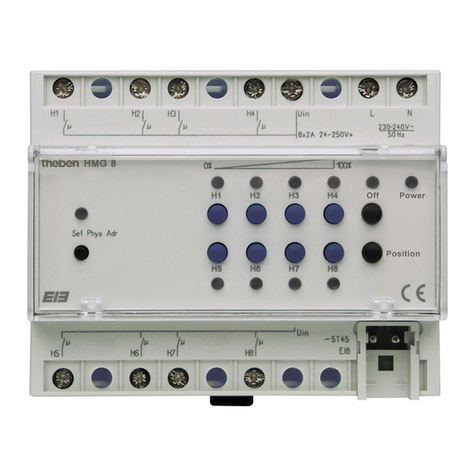
Heater actuators - Series
HMG 4
HME 4
The heater actuators for the series are as follows:
•BMG 4 (4-chanel basic module) and
•HME 4 (4-channel upgrademodule)
for controlling the heating valves via silent triac outputs.
The heater actuators are suitable for use with the European Installation -
Bus EIB in combination with the tproduct database. ETS
(EIB Tool Software) enables application programs to be selected, and spe-
cific parameters and addresses to be assigned and transferred to the
device.
A type BCU 2.1 bus coupling is integrated into the basic modules. A basic
module can be expanded simply by adding up to 2 upgrade modules.
Any combination of -series modules is possible, e.g.
HMG 4 + HME 4 + HME 4 (12 x heating)
HMG 4 S + RME 4 S + RME 4 S (4 x heating + 8 x
switching)
RMG 4 C-Last + DME 2 + HME 2 (4 x C-load + 2 x dimming
+ 4 x heating)
etc.
1.0 Designated use
The bus line must be routed, connected and installed in accordance with
the valid regulations to DIN-VDE and also the EIB Handbook and ZVEI/
ZVEH. The work may be carried out only by trained electricians qualified
to EIB.
Compliance with the national regulations and valid safety requirementsis
required. Tampering with or making modifications to the
device will invalidate the warranty.
Please note:
• It is permitted to connect different phases in one device.
• It is possible to connect contactable protective low voltage, if all 4
channels of a module switch protective low voltage.
• Switching protectors can be activated for controlling electric heaters,
for example.
3.0. Electrical connection
2.0 Description
309 321
1
2
6
3
4
5
HMG 4 Basic device
•The device controls thermal actuators via silent and
non-wearing triac outputs.
•The heating output can be continuously adjusted
as and when required. This is achieved by converting a continuous
control variable into a PWM (pulse width modulation) output signal.
Example:
HME 4 Upgrade module
Manual selector switch permanently - ON / OFF – Bus
operation
Manual switch in position:
The status of the triac is determined by the bus
messages.
The triac is permanently switched on.
The triac is permanently switched off.
Please note: Manual switching can also be used in the event
of a bus voltage failure.
Connection for actuators HMG 4 and HME 4
7
147
368
25
L3
L2
L1
H1 H2 H3 H4
N
L
M
L1
N
N
HMG 4
1 LEDs on = channelsH1 ... H4 switched on
2Programming key and LED for physical address
3Bus connection: Ensure correct polarity!
4Manual selector switch: e.g. Permanently On / Off or Bus
HME 4
5Plug as connection between upgrade module and basic device
6 LEDs on = channelsH1 ... H4 switched on
7Manual selector switch: e.g. Permanently On / Off or Bus

Aus
Ein
10 %
1 min.
10 min. 10 min.
5 min.
50 %
ON
OFF
6.0 Technical data
Open the slide on the right-hand side of the module.
Lock the module onto the distributing bus bar.
Push the modules fully together.
Connection:
Ensure correct polarity of the bus connection terminal.
Close the actuator as shown on the wiring diagram
in Chapter 3.0.
The bus is connected to the basic module.
5.0 Connecting an upgrade module
HMG 4 / HME 4
Mains power supply
Operating voltage: 230 V AC ± 10 %, 50 Hz
Power draw: 2.5 VA
Bus power supply
Power draw: max. 10 mA
Connection: bus terminal
Outputs
Quantity: 4
Type of contact: Triac
Nominal voltage: 24-230 V AC, 50 to 60 Hz
(L1, L2 or L3)
Nominal current: 0.5 A
This corresponds to 5 x 24 V AC theben actuators (Order no. 907 0 262)
Switching of different phases: possible
Switching of SELV voltages: possible if all channels of a
module switch protective low
voltage
The device is suitable for use in conditions with a normal level of polluti-
on. Observe deviating technical data on the device rating plate! Technical
changes reserved. The devices comply with European Directives 73/23/EEC
(low-voltage directive) and 89/336/EEC (EMC Directive).
If the devices are combined with others for use within a system, ensure
that the system as a whole does not cause radio interference.
The ETS database can be found under www.theben.de
Please refer to the Handbook for detailed functional descriptions.
Theben AG
Hohenbergstr. 32
D-72401 Haigerloch
Germany
Phone +49 (0) 74 74/6 92-0
Fax +49 (0) 74 74/6 92-150
Service
Phone +49 (0) 74 74/6 92-369
Fax +49 (0) 74 74/6 92-207
[email protected]
Addresses, telephone numbers etc. at
www.theben.de
Information in the event of bus failure
• If a mains supply is available, the triacs can be operated using the
manual switches should the bus fail.
• The behaviour after bus failure can be set via the application,
e.g. emergency mode.
4.0 Bus connection / (mains) power failure
Information in the event of power failure
If the mains power should fail, all triacs switch-off, irrespective of the
software configuration. This means that the power circuit is
interrupted.

This manual suits for next models

2

Other Theben Controllers manuals

Theben DU 1 User manual

Theben

Theben DU 1 User manual

Theben HMG 8 User manual

Theben

Theben HMG 8 User manual

Theben FCA 2 User manual

Theben

Theben FCA 2 User manual

Theben PH-II Series User manual

Theben

Theben PH-II Series User manual

Theben RM 4 H FIX1 User manual

Theben

Theben RM 4 H FIX1 User manual

Theben RMG 8 User manual

Theben

Theben RMG 8 User manual

Theben JMG 4 T KNX User manual

Theben

Theben JMG 4 T KNX User manual

Theben TC 649 E User manual

Theben

Theben TC 649 E User manual

Theben RAMSES 856 top2 Installation guide

Theben

Theben RAMSES 856 top2 Installation guide

Theben MIX 2 Series User manual

Theben

Theben MIX 2 Series User manual

Popular Controllers manuals by other brands

ADLINK Technology PXI-3920 user manual

ADLINK Technology

ADLINK Technology PXI-3920 user manual

Elko RFDEL-76M manual

Elko

Elko RFDEL-76M manual

IntesisBox FJ-RC-MBS-1 user manual

IntesisBox

IntesisBox FJ-RC-MBS-1 user manual

Gate WARFET user guide

Gate

Gate WARFET user guide

Kaysun KC-01 S owner's manual

Kaysun

Kaysun KC-01 S owner's manual

Danfoss PVED-CLS Startup guide

Danfoss

Danfoss PVED-CLS Startup guide

Val Controls IDC24-A user manual

Val Controls

Val Controls IDC24-A user manual

FW Murphy Centurion C5 M-VIEW Touch Series Operation manual

FW Murphy

FW Murphy Centurion C5 M-VIEW Touch Series Operation manual

Omega i-SERIES user guide

Omega

Omega i-SERIES user guide

Elos me LESCOLTON ICECOOL II DUAL SYSTEM user guide

Elos me

Elos me LESCOLTON ICECOOL II DUAL SYSTEM user guide

Bose 802 C II Service manual

Bose

Bose 802 C II Service manual

Renogy Wanderer Traveler Series manual

Renogy

Renogy Wanderer Traveler Series manual

Jordan Valve Mark 60 Series Installation & maintenance instructions

Jordan Valve

Jordan Valve Mark 60 Series Installation & maintenance instructions

Emerson Dixell XR40CX Installing and operating instructions

Emerson

Emerson Dixell XR40CX Installing and operating instructions

Trane Tracer ZN511 Installation and operation

Trane

Trane Tracer ZN511 Installation and operation

Regin CORRIGO C40-LON instruction manual

Regin

Regin CORRIGO C40-LON instruction manual

Toro Intelli-Sense TIS-612 user guide

Toro

Toro Intelli-Sense TIS-612 user guide

WEISS EF2 Series manual

WEISS

WEISS EF2 Series manual

manuals.online logo
manuals.online logoBrands
  • About & Mission
  • Contact us
  • Privacy Policy
  • Terms and Conditions

Copyright 2025 Manuals.Online. All Rights Reserved.