Theiling TH-305110017 User manual
Operation Manual
ROLLERMAT
Automatic mechanical filter for fresh and saltwater aquariums and garden ponds
Fresh and saltwater aquariums from 300 to 3000 l volume and garden ponds up to a volumeof
5000 l
The Rollermat removes waste particles from the water. Biological filters and protein skimmers
are
workload is eased
and the result is crystal clear water.
1. Construction
2.
Working principle
Water with waste particles passes through the filter fleece and enters into the central drum.
From here it flows back into the
filter sump. This results in the fleece picking up waste
particles –as this happens, the flow through the fleece decreases and the water level
outside
of the drum rises. When the water level reaches the maximum level, a float switch actuates
the f l e e c e d r i v e motor and the dirty fleece roll slowly
rotates and a small part of fresh
fleece is loaded on the drum. T his res u l t s i n an inc r e a sed flow through the filter
fleece a nd thus th e w ate r level dro p s . When th e l e v e l dro ps suf f i ciently,
the float switc h is de activate d an d the moto r sto ps . This process repeats
automatically. It will take 3 –6
months until
the complete fleece is used and has
to be
replaced - this depends on the waste
production in the system.
The Fleece is very fine. Even the smallest
particles are
removed. The dirt is filtered out
of the system,
before it is metabolized
biologically. This eases the workload of
biofilters and the protein skimmers.
The pores of the fleece are even fine enough
to
retain many protozoa, like fish parasites in
fresh and
saltwater. They cannot pass
through the fleece.
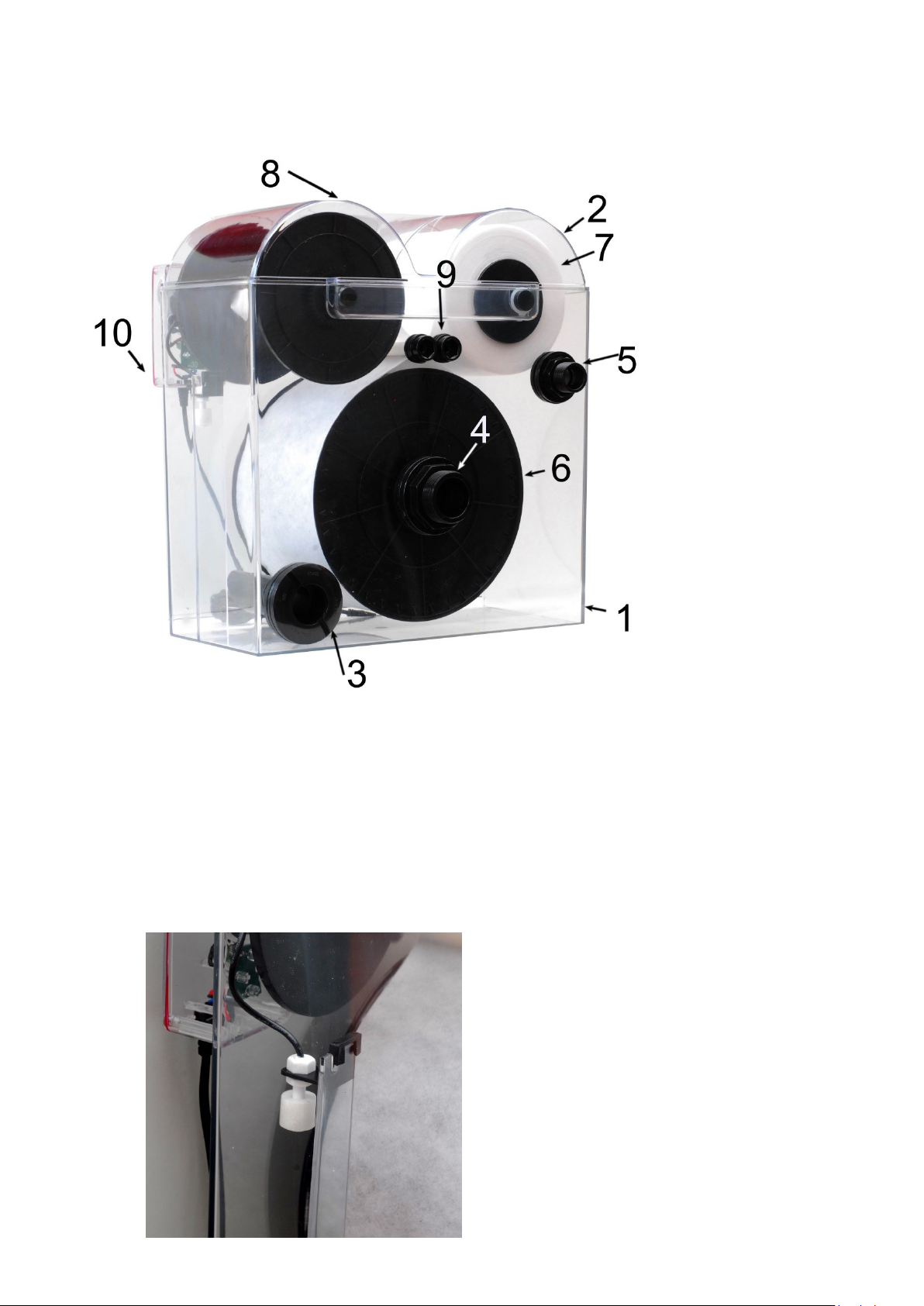
1.
1
.
1. Filter
2. Lid
3. Water inlet
4. Water outlet
5. Overflow
6. Filter Drum
7. New Fleece Roll
8. Dirty Fleece Roll
9. Directing Rolls
10. Level Switch

3. Features of the Rollermat:
Efficient mechanical filtration by fine filter
fleece
Automatic transport of the fleece.
The rolls are easy to change, up to 100 m length.
The roll is 15 cm wide, for flow rates up to 2700l/h, depending on the water quality.
Minimum power uptake. Average below 0.1w.
12V voltage –low safe voltage
The fleece is transported from the releasing roll to the
accepting roll. The rolls are driven by gear wheels .
If the accepting roll is full –or the releasing roll empty,
it
can be taken out of the filter easily. Both parts can
be
separated and the fleece can be discarded .Inserting a new
fleece roll.
Care must be taken when replacing the fleece roll –please
ensure the O-rings on the left and right side of the new roll are
mounted in the correct way - see the arrow on the figure at
the left. These O –rings prevent the roll from turning freely -
this keeps the fleece always taut.
The fleece is directed from the fresh roll over the first
directing
roll (see item 9). The end of the fleece can now be fixed to the
drum (by a tape) or just
pressed into the drum. The drum is
rotated carefully anti clockwise until the fleece can be reached
from the other
side.
Now, it is directed over the second directing roll and fixed on the accepting roll. This can be done
with
tape as well. If the accepting roll is in place and the transformer is plugged into the mains, thelevel
switch
can be lifted lightly by hand. The motor starts and the fleece is pulled taut.
4. Warning
When initially installing, the Rollermat will slowly increase the internal volume until filled to the normal
operating level –this will require approximately 20 litres of water. Please make sure you have enough
water to add to your aquarium/pond to replace this water (not ATO water! - disable any ATO device
until the Rollermat is filled to the bottom of the float switch.
During normal operation, the increase in water volume required to trigger the float switch and advance
the filter fleece, is only around 1 litre (when roll advances, this additional 1 litre is then returned to the
aquarium/pond). Therefore the impact on salinity/ATO operation is insignificant on tank sizes of 300
litres or more. On tanks volumes below this, the salinity/water level may be impacted and the
Rollermat is not recommended.
5.
Set Up
Aquarium: The Rollermat must be positioned so that the water outlet (which must not be reduced below
the 40mm)) can return water to the aquarium by gravity.
The Rollermat can be placed into the filter sump below the aquarium. Alternatively, it can be placed above
the water level, so that the purified water can flow freely back
into the aquarium.
Garden pond: The Rollermat is placed above the water level and is supplied with water by a pump.
The purified water flows freely back into the pond.
6. Connection
Water inlet
40 mm tank union/glue fitting
Water outlet
40 mm tank union/glue fitting
overflow
25 mm tank union/glue fitting
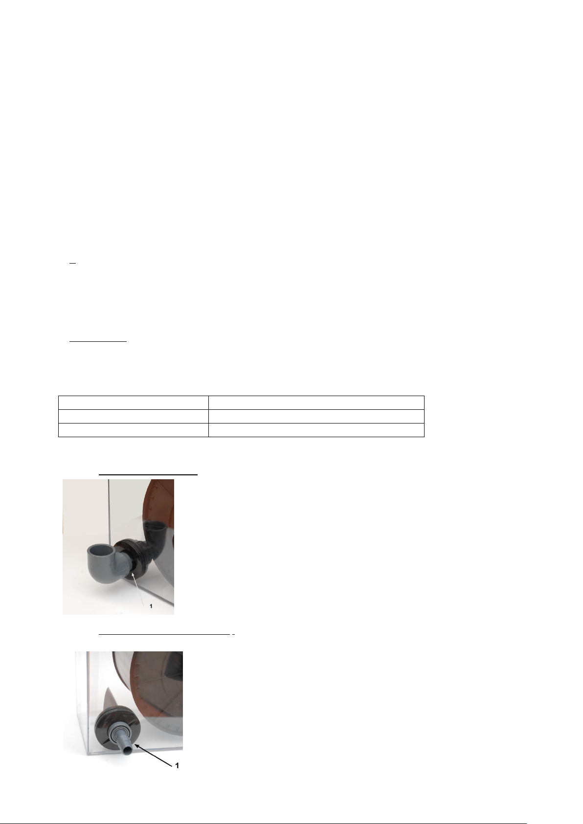
Water inlet
1. Water inlet by Gravity
If operated by gravity, the Rollermat is placed below the aquarium or below the
water level of the pond in the filter sump.
From the overflow chamber of the aquarium or from the skimmer of the pond a
pipe with a diameter of 40 mm is connected to the water inlet of the Rollermat
(1).
It is important, that the 40 mm pipe is just pressed into the tank union. If it is
glued, it the Rollermat cannot be disassembled for maintenance.
2. Water inlet by pump pressure.
If the Rollermat is supplied with water by a pump, the maximum flow is 2700l/h
(e.g. River 2700). The water inlet has to be reduced by a reduction fitting to a
¾” hose connector. This connections should be glued.
The Rollermat is placed above the water level of the aquarium or pond. The
water flows back by gravity into the aquarium or the pond.
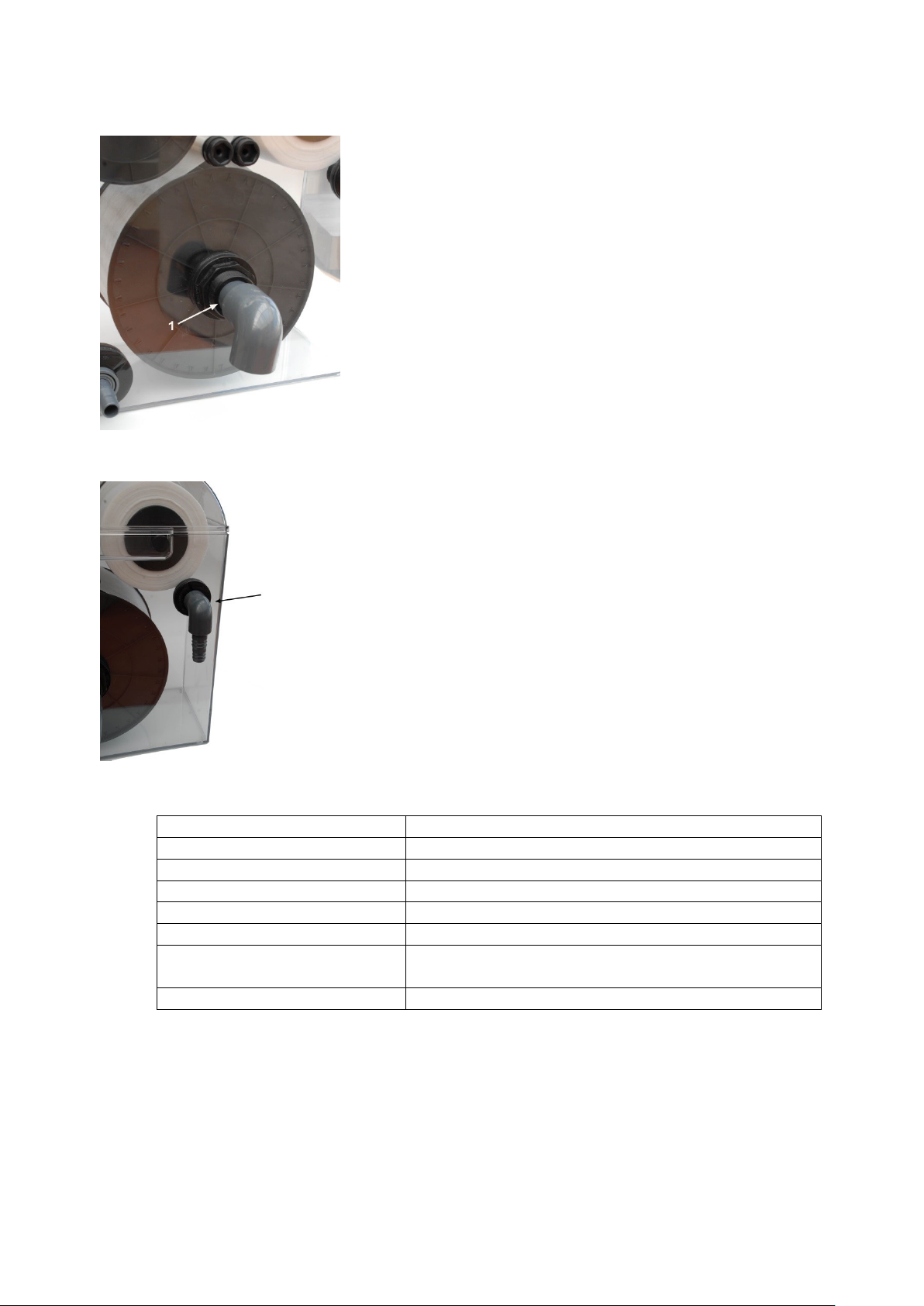
Water outlet
The water outlet may not be reduced. A 40 mm PVC pipe should be
presses into the tank union. From here a PVC pipe can be directed to the
filter sump or pond. The pipe should not be glued into the tank union. If
it is glued, the Rollermat cannot not be disassembled.
Alternatively a 40 mm hose fitting can be pressed into the tank union
and a hose may be directed to the pond or aquarium.
In any case, the water must flow freely away from the outlet. Neither a
PVC pipe nor a flexible hose may be directed higher than the outlet of
the Rollermat.
Overflow
The emergency overflow is a 25 mm tank union. Here, you can press in a 25 mm
PVC pipe. From here the pipe is directed downwards in a free flow pipe.
Alternatively a 25 mm hose connection can be pressed into the tank union and a
hose can be directed to the pond or aquarium.
6.
Technical data
Power supply motor
12V, 50/60Hz , 4 Watts
Transformer
230V/50 Hz
Water inlet
D 40 glue connection, 1 ¾“ thread
Water outlet
D 40 glue connection, 1 ¾“ thread
overflow
D 25 glue connection, 1 “ thread
Width of the fleece roll
15 cm
Maximum water level, if placed
in a filter sump
12,5 cm above the bottom of the Rollermat
Dimensions (L x W x H)
42 x 25 x 45 cm
7.
Accessories: Spare fleece rolls
Article number: 3051100171 spare roll Aquarium “Fine“, 40g/m², 45m long
Article number: 3051100172 spare roll Pond “Standard“, 20g/m², 90m long

9. Failures
The fleece is not transported. This may have different reasons:
-The fleece is not lying straight on the drum; there is a gap between fleece and drum. Unfiltered
water can pass through this gap. The water level inside of the Rollermat will not rise high enough to
touch the level switch. Action: tear the fleece straight and set up the Rollermat straight (water
balance)
-The motor turns, however the fleece is not transported. The gear wheel on the shaft of the motor
does not turn. Reason: The gear wheel is broken and has to be changed. It is only pressed on the
shaft and can be removed by hand or with the help of a lever.
-The motor does not turn although the water level in the Rollermat is above the level switch and
already flows through the emergency overflow. This may have different reasons:
-If the red LED in the electric compartment is off, the transformer or the PCB are broken.
-The red LED is on, however the motor does not react on the level switch. In this case either the
motor or the level switch are broken. If the motor is broken, the electric compartment should be
warm, because the motor tries to turn. If the level switch is broken, the compartment will be cold,
because the motor is not switched on.
-All parts can be changed easily.
10.Warranty
Should any defect in material or workmanship be found within 12 months of the date of purchase,
Theiling GmbH undertakes to repair or, at our option, replace the defective part free of charge–
always provided the product has been installed correctly, is used for the purpose that was intended
by us, is used in accordance with the operating instructions and is returned to us carriage paid. The
warranty term is not applicable on the all consumable products. Proof of Purchase is requiredby
presentation of an original invoice or receipt indicating the dealer’s name, the model number and
date of purchase, or a Guarantee Card if appropriate. This warranty may not apply if any model or
production number has been altered, deleted or removed, unauthorized persons ororganisations
have executed repairs, modifications or alterations, or damage is caused by accident, misuseor
neglect. We regret we are unable to accept any liability for any consequential loss. Please notethat
the product is not defective under the terms of this warranty where the product, or any of its
component parts, was not originally designed and / or manufactured for the market in which it is
used. These statements do not affect your statutory rights as a customer. If your TheilingGmbH
product does not appear to be working correctly or appears to be defective, please contact your
dealer in the first instance. Before calling your dealer, please ensure you have read andunderstood
the operating instructions. If you have any questions your dealer cannot answer, please contact us.
Our policy is one of continual technical improvement and we reserve the right to modify and adjust
the specification of our products without priornotification.

Spare parts list
art no
name
3051100180
lid
3051100181
Roll
(delivering)
3051100182
Roll
/(receiving)
3051100183
Direction roll
for fleece
3051100184
Drum
3051100185
Rung for the
drum
3051100186
Screw
3051100187
Nut
3051100203
Square ring
3051100204
washer
3051100205
Tank Union
25 mm
(overflow)
3051100206
Tank Union
(40mm) for
inlet and
outlet
art no
/name
3051100207
Deckel
Elektro-
modul
Lid for
electric
module
3051100208
Screws for
the lid
3051100209
Sealing for
the lid
3051100174
Motor
3051100188
Gear wheel
3051100189
Sealing for
motor
3051100178
Level switch
3051100190
Sealing for
level switch
3051100200
Holder for
level switch
3051100201
Circuit plate
3051100202
Connection
cable
3051100177
Transformer
Theiling GmbH, Maschweg 49, D-49324 Melle - 10/2016
- Technical changes reserved –
This manual suits for next models
1
Other Theiling Water Filtration System manuals


Popular Water Filtration System manuals by other brands


SteriPEN
SteriPEN Adventurer user guide

Ispring
Ispring DF1 Series user manual

Laica
Laica Fast Disk FD03A Instructions and warranty

Trigano
Trigano J-PSC064 Instruction and maintenance manual

Danfoss
Danfoss AHF 005 operating instructions

Acqua Brevetti
Acqua Brevetti BravoMAX M Installation and operating manual

Beko
Beko CLEARPOINT Series operating manual

SkyJuice
SkyJuice SkyHydrant Set up and operating instructions

Graco
Graco 213-062 instructions

UV Pure Technologies
UV Pure Technologies UPSTREAM instruction manual

amiad
amiad SAF X Series Installation, operation & maintenance instructions

HEISSNER
HEISSNER FPU24000-00 Instructions for use