TheMagicTouch HTP123 PRO User manual
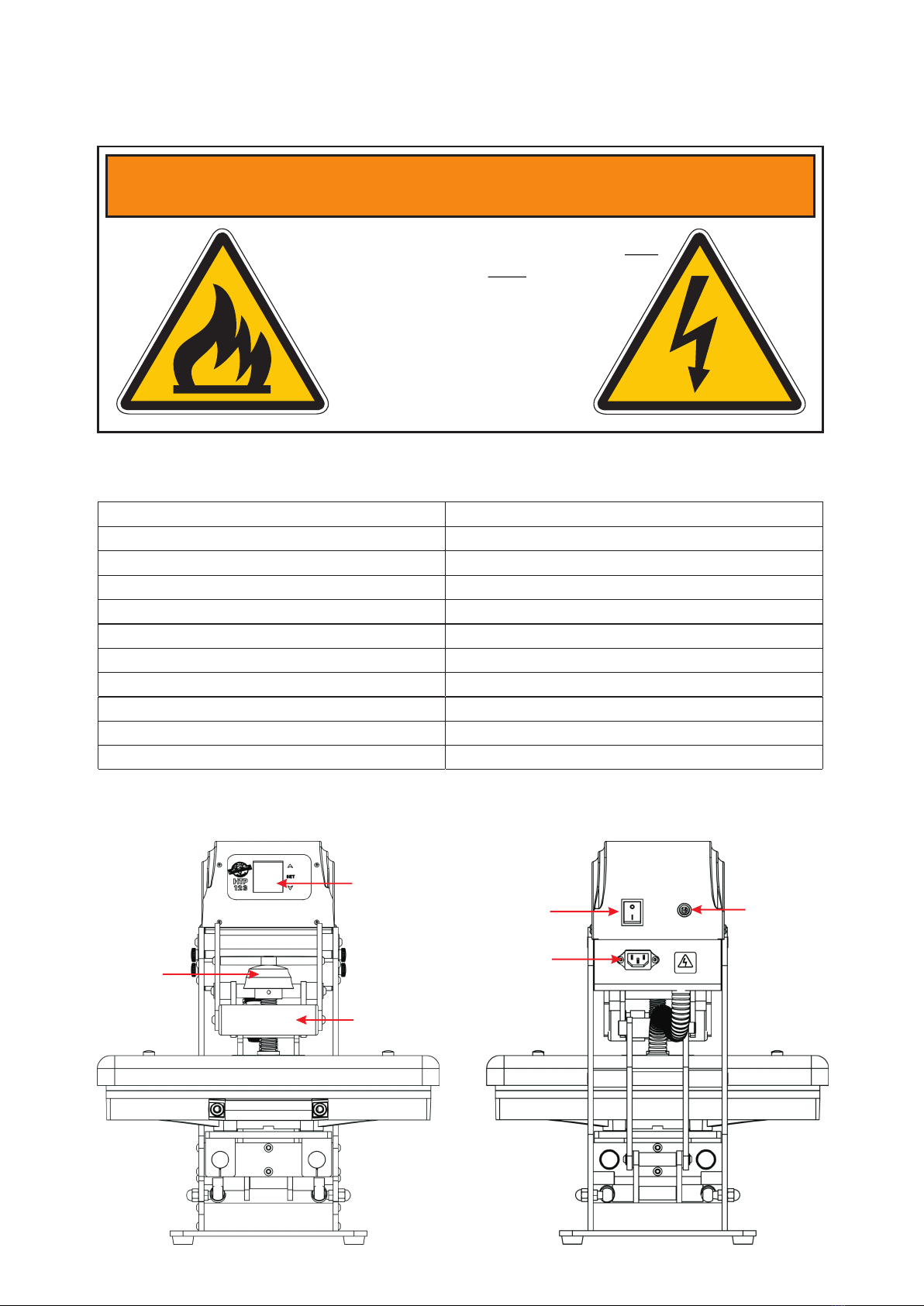
WARNING! - CAUTION!
Note: This device must be operated by one
professional operator only! Keep hands
clear from moving parts! Hot surface!
Don't touch Heater during operation!
Remove from power supply for all
maintenance and servicing
to avoid electrical
shock!
Operator Manual
HTP123 PRO HeatPress
Copyright TheMagicTouch, Germany 2020
Specifications
Dimensions, open (L x W X H)
63 x 44 x 86 cm
Printable Area
42 x 42 cm / 16.5” x 16.5”
Weight
46.5 kg
Voltage
110-120/220-240 V
Amperage 120V - 16.4A / 240V - 8.2A
Wattage
1800 W
Environmental Conditions 10-40°C / 50-105 , 30-70% RH°F
Temperature Range 80°C / 176°F to 220°C / 430°F
Timer Range 0-999 Seconds
Warranty 10 Years on HeatPlaten / 2 Year Parts
Controller
LCD Display
Handle
Power
Switch
Power
Socket
Circuit
Breaker
Pressure
Knob
Counter Range 0-999
Machine Legend
Copyright TheMagicTouch, Germany 2020
In case of Operating Trouble please contact your local TheMagicTouch Office, Distributor or
Dealer or TheMagicTouch GmbH, Germany at +49 6071 921 800. www.themagictouch.com
Electrical Schematic 110-120V
Electrical Schematic 220-240V
34 J.03.03.0070 washer 20-13-25 GC1-10B 2
35 J.02.01.0001 Heat pLaten HP-16.5*16.5-A-S 1
36 J.03.06.0169 Blance screw 1
37 J.03.04.0076 Thermocouple PT100 1
38 J.03.04.0062 Thermostat TMS-01 1
39 J.03.05.0146 Heater cover A2 GC1-46-2 1
40 J.03.05.0381 PP tube joint GZ-101 1
41 J.04.04.0006 PP tube 1
42 J.03.06.0136 Cup heat bolt M8*20 1
44 J.03.06.0186 Flat washer 20*8*2 1
45 J.03.05.0382 Pressure screw base bolt GC1-104 1
46 J.03.06.0149 Set screw M5-L4 1
47 J.03.05.0380 Pressure Screw GH-47 1
48 J.03.05.0140 Pressure Knob 1
49 J.03.03.0016 Foam Grip 1
50 J.02.05.0007 Handle Shaft 1
51 J.03.05.0132 Machine arm B GC1-05B-Y 2
52 J.03.05.0142 Holding Sheet 1 GC1-03A 1
53 J.03.06.0058 Magnet MT-01-B 1
54 J.03.05.0575 Arm link D 2
55 J.02.05.0005 Threaded pin 12-126 GC1-19 1
56 J.03.05.0080 Aluminium sleeve 17-13-76 GC1-27 1
57 J.03.05.0141 Heater holding block GS-101ZB 1
59 J.02.05.0006 Threaded pin 12-89 GC1-20 1
64 J.03.05.0576 Arm link D 2
65 J.03.01.0014 Sticker HTP123 1
66 J.03.05.0130 Controller box cover CB-01 1
67 J.03.04.0139 Controller board GSK-G04 1
68 J.02.04.0131 Traic DX146-10 1
69 J.03.04.0078 Terminal Block 1
70 J.03.04.0077 Socket DB-14-1 1
71 J.02.04.0139 Circuit Breaker 10A 1
72 J.03.05.0131 Controller box base C-2 NP161130 1
73 J.03.04.0127 Magnet switch M8*30 1
74 J.02.04.0094 5 phase aviation plug(Female)with wires welded 1
75 J.02.04.0093 5 phase aviation plug(Male) with wires welded 1
Copyright TheMagicTouch, Germany 2020
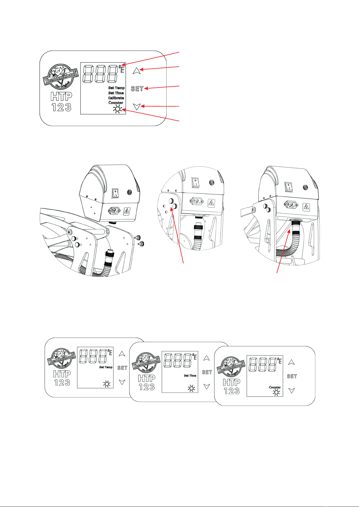
Control Panel Legend
LCD Display Set Temperature when lit
Up/+ Button
Down/- Button
Mode Selection Button
Set Time when lit Set Counter when lit
Controller Assembly
1. Insert Controller between
the Frame
2. Insert and tighten the
Hand Screws 3. Attach Heat Platen
Cable and tighten
the Screw Ring
Attach the Power Cable and switch the machine on. The Controller LCD should illuminate.
Adjusting Temperature, Time, Counter and Pressure
Press Set Button > ‘Set Temp’ will be lit > Select Temperature with the Up or Down Button >
Press Set Button again > ‘Set Time’ will be lit > Select Time with the Up or Down Button >
Press Set Button again > ‘Counter’ will be lit > Use the Down Button to re-set Counter to 1.
Press the Set Button again to return to StandBy/Idle. If you don’t need to make changes
just press the Set Button again to skip the Mode. At the end all Mode Indicators must be off
to return to StandBy/Idle.
To adjust the Pressure turn Pressure Knob clockwise to increase the pressure and counter-
clockwise to decrease. High pressure would be the point where you just still can close and
lock the press.
Warm-up when moving
C/F Temperature Range Indicator
Copyright TheMagicTouch, Germany 2020
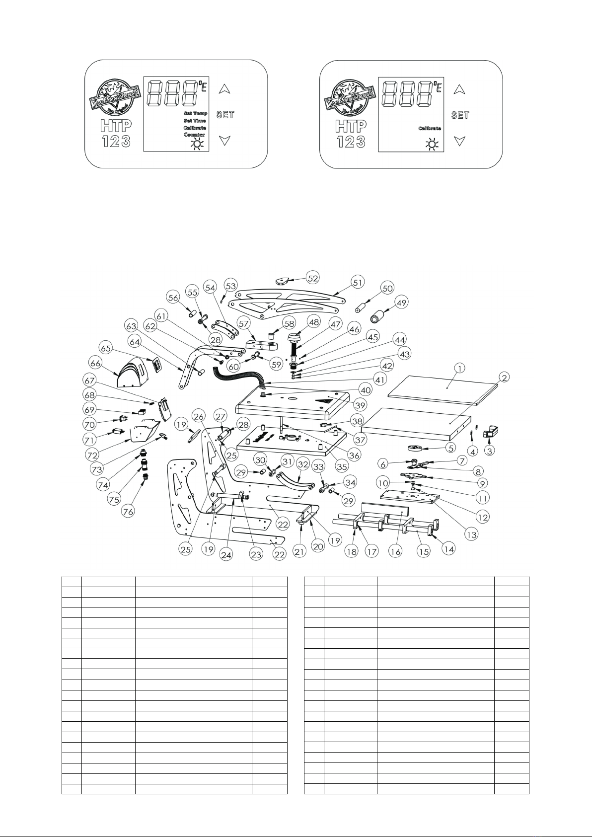
Switch between C and F Temperature Calibration
Press the Set and the Up Button together
and hold for 3 Seconds to switch between
the C and F temperature range. The selected
will be shown by the C/F Temp Indicator.
Press the Set and the Down Button together
for 3 Seconds to enter the Calibration Mode.
“Calibrate” will be lit. Use Up or Down Button
to adjust the Value. Press Set button to quit.
Explosion View and Parts List
No. Material No. Name Qty
1 J.03.07.0002 Silicon pad SP-16.5*16.5-9-G 1
2 J.02.02.0033 Lower platen LP-16.5*16.5-C-S 1
3 J.03.06.0053 Handle JZN43 1
4 J.04.06.0004 Heat insulation sheet 2
5 J.03.05.0123 Ramlock female part GH-111 1
6 J.03.05.0126 Ramlock male part GH-114 1
7 J.03.05.0122 Ramlock handle GH-1131 1
8 J.03.05.0125 Ramlock locking set GH-113 1
9 J.03.05.0124 Ramlock base GH-112 1
10 J.03.06.0064 Spring washer 15*10*0.3 1
11 J.03.06.0063 Flat washer 16*10*1 1
12 J.03.05.0392 Ramlock screw GH-24-B 1
No. Material No. Name Qty
13 J.03.05.0139 Lower platen base B GCT-03B 1
14 J.03.05.0144 Bearing base GCT-02 4
15 J.02.05.0008 Axostyle B GCT-05B 2
16 J.03.05.0143 Holding block B GCT-04B 1
17 J.03.03.0008 O-shape washer WSH-02 4
18 J.03.05.0145 Axostyle holding block GCT-01 2
19 J.03.05.0136 Holding block B GC1-17 3
20 J.03.05.0137 Machine foot base GC1-02 2
21 J.03.03.0037 Rubber foot XD2512-148 2
22 J.03.05.0135 Machine body B GC1-01B 2
23 J.03.03.0029 Washer for gas spring 25*φ15 TB-17 2
24 J.03.06.0048 Gas spring 18-80-270N 2
25 J.02.05.0002 Threaded pin 13-164 GC1-18 2
26 J.03.03.0062 washer 20-13-39.5 GC1-11 2
27 J.02.05.0002 Threaded pin 13-164 GC1-18 2
28 J.03.03.0066 washer 20-13-12.75 GC1-10 4
29 J.03.05.0078 Aluminium sleeve 14-10-44 GC1-09A 1
30 J.03.05.0078 Aluminium sleeve 14-10-44 GC1-09A 1
32 J.03.05.0138 Gas spring arm link B GC1-24B-Y 2
33 J.03.05.0078 Aluminium sleeve 14-10-44 GC1-09A 2
Copyright TheMagicTouch, Germany 2020
Control Panel Legend
LCD Display Set Temperature when lit
Up/+ Button
Down/- Button
Mode Selection Button
Set Time when lit Set Counter when lit
Controller Assembly
1. Insert Controller between
the Frame
2. Insert and tighten the
Hand Screws 3. Attach Heat Platen
Cable and tighten
the Screw Ring
Attach the Power Cable and switch the machine on. The Controller LCD should illuminate.
Adjusting Temperature, Time, Counter and Pressure
Press Set Button > ‘Set Temp’ will be lit > Select Temperature with the Up or Down Button >
Press Set Button again > ‘Set Time’ will be lit > Select Time with the Up or Down Button >
Press Set Button again > ‘Counter’ will be lit > Use the Down Button to re-set Counter to 1.
Press the Set Button again to return to StandBy/Idle. If you don’t need to make changes
just press the Set Button again to skip the Mode. At the end all Mode Indicators must be off
to return to StandBy/Idle.
To adjust the Pressure turn Pressure Knob clockwise to increase the pressure and counter-
clockwise to decrease. High pressure would be the point where you just still can close and
lock the press.
Warm-up when moving
C/F Temperature Range Indicator
Copyright TheMagicTouch, Germany 2020
Switch between C and F Temperature Calibration
Press the Set and the Up Button together
and hold for 3 Seconds to switch between
the C and F temperature range. The selected
will be shown by the C/F Temp Indicator.
Press the Set and the Down Button together
for 3 Seconds to enter the Calibration Mode.
“Calibrate” will be lit. Use Up or Down Button
to adjust the Value. Press Set button to quit.
Explosion View and Parts List
No. Material No. Name Qty
1 J.03.07.0002 Silicon pad SP-16.5*16.5-9-G 1
2 J.02.02.0033 Lower platen LP-16.5*16.5-C-S 1
3 J.03.06.0053 Handle JZN43 1
4 J.04.06.0004 Heat insulation sheet 2
5 J.03.05.0123 Ramlock female part GH-111 1
6 J.03.05.0126 Ramlock male part GH-114 1
7 J.03.05.0122 Ramlock handle GH-1131 1
8 J.03.05.0125 Ramlock locking set GH-113 1
9 J.03.05.0124 Ramlock base GH-112 1
10 J.03.06.0064 Spring washer 15*10*0.3 1
11 J.03.06.0063 Flat washer 16*10*1 1
12 J.03.05.0392 Ramlock screw GH-24-B 1
No. Material No. Name Qty
13 J.03.05.0139 Lower platen base B GCT-03B 1
14 J.03.05.0144 Bearing base GCT-02 4
15 J.02.05.0008 Axostyle B GCT-05B 2
16 J.03.05.0143 Holding block B GCT-04B 1
17 J.03.03.0008 O-shape washer WSH-02 4
18 J.03.05.0145 Axostyle holding block GCT-01 2
19 J.03.05.0136 Holding block B GC1-17 3
20 J.03.05.0137 Machine foot base GC1-02 2
13 J.03.05.0139 Lower platen base B GCT-03B 1
14 J.03.05.0144 Bearing base GCT-02 4
15 J.02.05.0008 Axostyle B GCT-05B 2
16 J.03.05.0143 Holding block B GCT-04B 1
17 J.03.03.0008 O-shape washer WSH-02 4
18 J.03.05.0145 Axostyle holding block GCT-01 2
19 J.03.05.0136 Holding block B GC1-17 3
20 J.03.05.0137 Machine foot base GC1-02 2
21 J.03.03.0037 Rubber foot XD2512-148 2
22 J.03.05.0135 Machine body B GC1-01B 2
23 J.03.03.0029 Washer for gas spring 25*φ15 TB-17 2
24 J.03.06.0048 Gas spring 18-80-270N 2
25 J.02.05.0002 Threaded pin 13-164 GC1-18 2
26 J.03.03.0062 washer 20-13-39.5 GC1-11 2
27 J.02.05.0002 Threaded pin 13-164 GC1-18 2
28 J.03.03.0066 washer 20-13-12.75 GC1-10 4
29 J.03.05.0078 Aluminium sleeve 14-10-44 GC1-09A 1
30 J.03.05.0078 Aluminium sleeve 14-10-44 GC1-09A 1
32 J.03.05.0138 Gas spring arm link B GC1-24B-Y 2
33 J.03.05.0078 Aluminium sleeve 14-10-44 GC1-09A 2

WARNING! - CAUTION!
Note: This device must be operated by one
professional operator only! Keep hands
clear from moving parts! Hot surface!
Don't touch Heater during operation!
Remove from power supply for all
maintenance and servicing
to avoid electrical
shock!
Operator Manual
HTP123 PRO HeatPress
Copyright TheMagicTouch, Germany 2020
Specifications
Dimensions, open (L x W X H)
63 x 44 x 86 cm
Printable Area
42 x 42 cm / 16.5” x 16.5”
Weight
46.5 kg
Voltage
110-120/220-240 V
Amperage 120V - 16.4A / 240V - 8.2A
Wattage
1800 W
Environmental Conditions 10-40°C / 50-105 , 30-70% RH°F
Temperature Range 80°C / 176°F to 220°C / 430°F
Timer Range 0-999 Seconds
Warranty 10 Years on HeatPlaten / 2 Year Parts
Controller
LCD Display
Handle
Power
Switch
Power
Socket
Circuit
Breaker
Pressure
Knob
Counter Range 0-999
Machine Legend
Copyright TheMagicTouch, Germany 2020
In case of Operating Trouble please contact your local TheMagicTouch Office, Distributor or
Dealer or TheMagicTouch GmbH, Germany at +49 6071 921 800. www.themagictouch.com
Electrical Schematic 110-120V
Electrical Schematic 220-240V
34 J.03.03.0070 washer 20-13-25 GC1-10B 2
35 J.02.01.0001 Heat pLaten HP-16.5*16.5-A-S 1
36 J.03.06.0169 Blance screw 1
37 J.03.04.0076 Thermocouple PT100 1
38 J.03.04.0062 Thermostat TMS-01 1
39 J.03.05.0146 Heater cover A2 GC1-46-2 1
40 J.03.05.0381 PP tube joint GZ-101 1
41 J.04.04.0006 PP tube 1
42 J.03.06.0136 Cup heat bolt M8*20 1
44 J.03.06.0186 Flat washer 20*8*2 1
45 J.03.05.0382 Pressure screw base bolt GC1-104 1
46 J.03.06.0149 Set screw M5-L4 1
47 J.03.05.0380 Pressure Screw GH-47 1
48 J.03.05.0140 Pressure Knob 1
49 J.03.03.0016 Foam Grip 1
50 J.02.05.0007 Handle Shaft 1
51 J.03.05.0132 Machine arm B GC1-05B-Y 2
52 J.03.05.0142 Holding Sheet 1 GC1-03A 1
53 J.03.06.0058 Magnet MT-01-B 1
54 J.03.05.0575 Arm link D 2
55 J.02.05.0005 Threaded pin 12-126 GC1-19 1
56 J.03.05.0080 Aluminium sleeve 17-13-76 GC1-27 1
57 J.03.05.0141 Heater holding block GS-101ZB 1
59 J.02.05.0006 Threaded pin 12-89 GC1-20 1
64 J.03.05.0576 Arm link D 2
65 J.03.01.0014 Sticker HTP123 1
66 J.03.05.0130 Controller box cover CB-01 1
67 J.03.04.0139 Controller board GSK-G04 1
68 J.02.04.0131 Traic DX146-10 1
69 J.03.04.0078 Terminal Block 1
70 J.03.04.0077 Socket DB-14-1 1
71 J.02.04.0139 Circuit Breaker 10A 1
72 J.03.05.0131 Controller box base C-2 NP161130 1
73 J.03.04.0127 Magnet switch M8*30 1
74 J.02.04.0094 5 phase aviation plug(Female)with wires welded 1
75 J.02.04.0093 5 phase aviation plug(Male) with wires welded 1
Other TheMagicTouch Power Tools manuals


