Little Machine Shop Mini Mill User manual

The premier source of tooling, parts, and accessories for bench top machinists.
Mini Mill User’s Guide
from LittleMachineShop.com

© Copyright 2006, LittleMachineShop.com
All rights reserved.
Photos © Copyright 2006, PhotoBoost.com
All rights reserved.
Written by Chris Wood of LittleMachineShop.com.
LittleMachineShop.com
http://www.littlemachineshop.com
396 W. Washington Blvd. #500, Pasadena, CA 91103
(800) 981-9663 • Fax (626) 797-7934
2

Contents
Introduction................................................................................. 5
Specifications............................................................................... 5
Safety Considerations ..................................................................... 5
Features ..................................................................................... 6
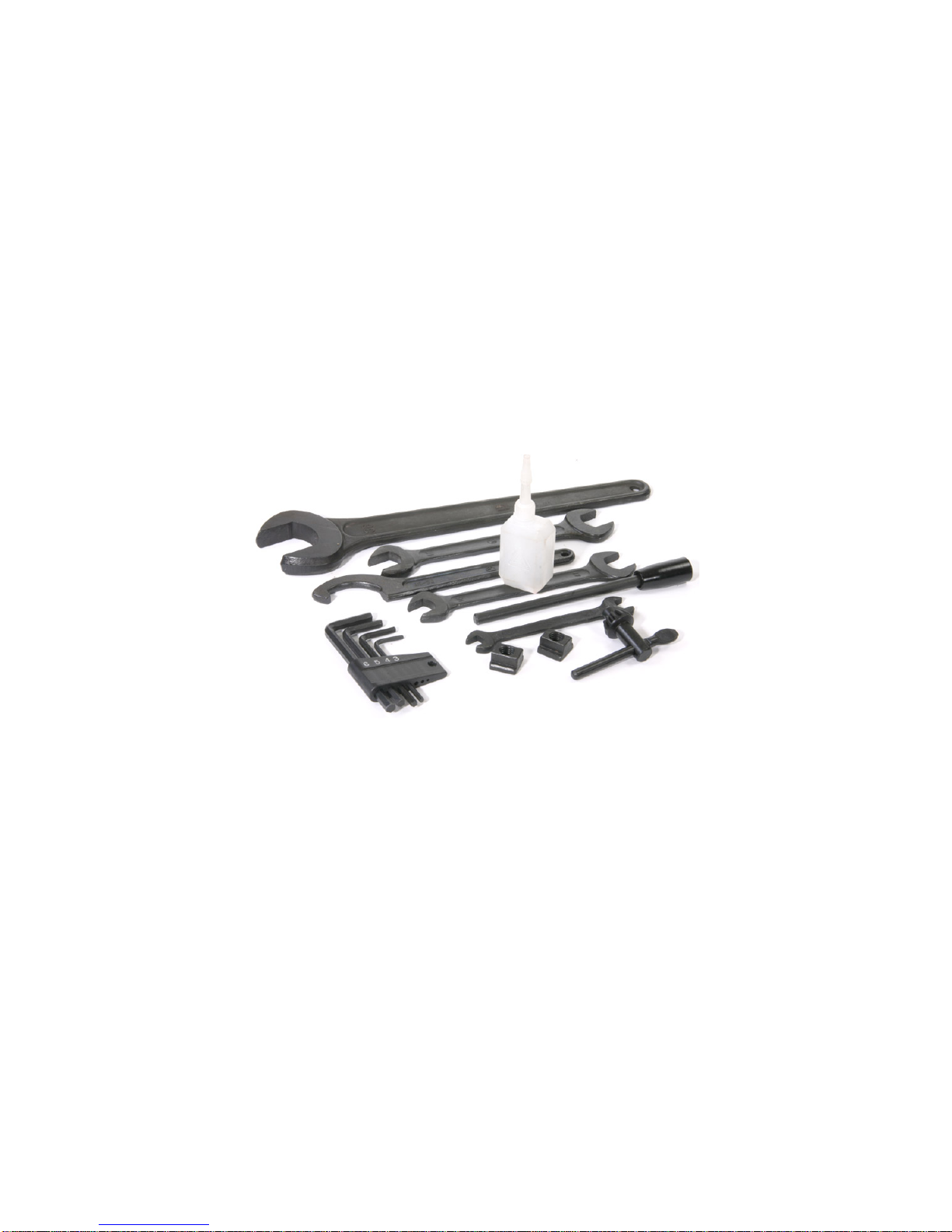
Basic Accessories........................................................................... 7
Cleaning ..................................................................................... 7
Mounting Your Mill ......................................................................... 7
Operating Controls......................................................................... 8
Motor Controls ........................................................................... 9
High/Low Speed Shifter ...............................................................10
X-Axis Hand Wheel .....................................................................10
X-Axis Lock Lever.......................................................................11
Y-Axis Hand Wheel .....................................................................11
Y-Axis Lock Lever.......................................................................11
Z-Axis Coarse Feed Handles...........................................................11
Z-Axis Fine Feed Knob .................................................................11
Z-Axis Lock Lever.......................................................................12
Adjustments................................................................................12
X-Axis Gib................................................................................12
Y-Axis Gib................................................................................13
Z-Axis Gib................................................................................13
Tramming the Mill......................................................................14
Motor to Intermediate Gear Adjustment ...........................................15
Lubrication.................................................................................16
Lubricating the Transmission Gears .................................................16
Changing Spindle Tools...................................................................17
Squaring a Vise ............................................................................18
Using Parallels .............................................................................19
Clamping with a Clamping Kit...........................................................20
Finding the Edge of a Workpiece .......................................................20
Drilling ......................................................................................22
Milling.......................................................................................23
Conventional Milling Versus Climb Milling.............................................24
Plunge Milling..............................................................................24
Milling Slots ................................................................................25
Surfacing....................................................................................25
3

Common Accessories......................................................................25
End Mills .................................................................................25
Work Holding............................................................................26
Vises ......................................................................................26
Clamping Kits and Accessories .......................................................27
Setup Tools..............................................................................28
Maintenance ...............................................................................28
Cleaning..................................................................................28
Motor Brushes...........................................................................28
4

Introduction
This user’s guide covers the mini mills that are sold by Grizzly Industrial,
Harbor Freight Tools, Homier Mobile Merchants, Micro-Mark, Cummins Tools,
and Wholesale Tool.
These mills are made in China, in several different factories, but to a similar
set of plans. The general operating principles covered in this document are
common to all of them.
Specifications
The following specifications are common to these mills.
Metric Imperial
Drilling capacity 13 mm dia ½” dia
End mill capacity 16 mm dia 5/8” dia
Face mill capacity 30 mm dia 1.2” dia
X-axis travel 220 mm 8.7”
Y-axis travel 100 mm 3.9”
Z-axis (spindle) travel 180 mm 7”
Spindle tilt ±45° ±45°
Motor power 350 W 0.47 HP
Spindle speed Low range 0-1100 rpm 0-1100 rpm
Spindle speed High range 0-2500 rpm 0-2500 rpm
Spindle taper 3MT or R8 3MT or R8
T-slot width 12 mm 7/16”
Weight (net/gross) 50/68 kg 110/150 lb.
Package size (L x W x H) 560 x 500 x 740 mm 22 x 19.7 x 29.2”
Safety Considerations
Always use common sense when using a power tool. Review the safety
instructions that came with your mill. Besides the general safety rules for any
power tool, the following are specific considerations for the mini mill.
•Your mini mill is just that, a mini, or small mill. Don’t attempt jobs that are
beyond its capacity.
•Check the workpiece after you secure it in the vise or other work holding
device. Be sure it is secure before turning on the mill.
•Don’t wear loose clothing or jewelry when operating the mill.
5

Features
1
11
2
3
12
4
13
5
6 14
7 15
16
1. Motor
2. Drawbar (under
cap)
3. High/low speed
shifter
4. Motor controls
5. Spindle
6. Drill chuck
7. Table
8. Saddle
9. X-axis lock lever
10.Y-axis hand wheel
11.Z-axis fine feed
knob
12.Z-axis coarse feed
handle
13.Z-axis lock lever
14.Column
15.Z-axis travel stop
16.X-axis hand wheel
17.Y-axis lock lever
18.Base
8
9 17
18
10
6

Basic Accessories
The following accessories come with most mini mills. Some mini mills come
with additional accessories.
13 mm (1/2”) drill chuck and appropriate arbor
Drawbar
Spindle locking pin
Two T-slot nuts
Oil can
Spanner wrench for spindle nut
Hex wrenches 3, 4, 5, and 6 mm
Open end wrenches 8 x 10 mm, 14 x 17 mm, 17 x 19 mm, and 36 mm.
Cleaning
Your mill will arrive coated with grease to protect it from corrosion during
shipment. Follow this procedure to remove the grease:
1. Wipe most of the grease off with rags or paper towels.
2. Clean the surfaces with mineral spirits (paint thinner).
3. Coat the surfaces with oil.
See the “Lubrication” section on page 16 for specific recommendations for
lubricants.
Mounting Your Mill
The mini mill must be bolted down to the workbench because it is top-heavy. It
is unsafe to operate the mini mill if it is not bolted to a workbench.
Before you mount your mini mill, plan the positioning carefully. If you simply
bolt it to the middle of the workbench, you won’t be able to turn the Y-axis
hand wheel. Either mount the mini mill at the front edge of the bench so the Y-
7

axis hand wheel hangs over the edge of the bench, or mount the mini mill on a
riser about 1.5” thick to provide room to turn the Y-axis hand wheel. The
mounting bolts must extend through the riser and bolt the mill to the bench to
keep it from tipping.
Be sure that you have room on both sides of the mill for the X-axis travel. The
table will move to the right so that the left end of the table is almost flush
with the saddle. You need an additional 8” to the right so that you can remove
the table off the right side of the mill. The table moves to the left so that the
right end of the table is almost flush with the saddle.
The following diagram shows the holes required to mount the mill and the clear
area around the bolt pattern to allow use and maintenance of the mini mill.
Mount the mill to the workbench with 3/8” or 10 mm bolts. The bolts should be
about 1” (25 mm) longer than the thickness of the workbench. Use fender
washers on the underside of wooden benches to prevent the nuts from pulling
through.
Operating Controls
There are several controls used to operate the mill. Become familiar with them
before you use the mill.
8

Motor Controls
1
2
1. Power switch
2. Speed control
The power switch latches in the off position when you press the big red button.
To turn the switch on, slide the big red button in the direction of the arrow.
The big red button will swing up to the on position.
The power switch interrupts the input power to the speed control circuit
board.
You control the motor speed by adjusting a potentiometer that provides the
speed setting value to the speed control circuit board. There is a safety switch
on the speed control potentiometer that forces you to return the control to
minimum speed when starting the mill.
Always turn the speed control to the minimum speed position before starting
the mill. Starting the mill with the speed control set to a higher speed can
damage the speed control circuit board.
To power up the mill:
1. Turn the speed control to the minimum speed position.
2. Turn on the power by sliding the red cover of the switch up to release the
latch.
Always turn the power off when you leave the mill. Leaving the power on can
damage the speed control circuit board.
To power down the mill:
1. Turn the speed control to the minimum speed position.
2. Turn off the power by latching the red cover of the switch.
9

To start the mill:
1. Ensure that the speed control is set to the minimum speed position.
2. Advance the speed control to the desired speed.
To stop the mill:
•Turn the speed control to the minimum speed position.
High/Low Speed Shifter
The high/low speed shifter is on the left side of the spindle housing. It selects
the spindle speed range.
Low speed range 0-1100 RPM
High speed range 0-2500 RPM
Never move this lever when the mill is turning. You might need to turn the
spindle slightly by hand as you move the high/low speed shifter to engage the
gears.
X-Axis Hand Wheel
The X-axis hand wheel moves the table to the left or right, depending on which
way it is turned. Use this hand wheel to position the table.
The dial on this handle indicates the relative position of the table. The
graduated dial can be repositioned for convenience. Each division of the dial
represents a movement of 0.001”.
On some mini mills there are 62.5 divisions on the dial. On these mills, each
full turn of the hand wheel moves the table 1/16” (0.0625”).
Other mini mills have 50 graduations on the dial. On these mills, each full turn
of the hand wheel moves the table 0.050”.
10

X-Axis Lock Lever
The X-axis lock lever is on the front of the saddle behind the Y-axis hand
wheel. Use this lever to lock the X-axis so it does not move inadvertently.
Pulling out on the lever and simultaneously turning it can change the locked
position of this lever. Pulling out disengages the lever from the locking screw
and allows it to move to a different position. You might need to adjust the
screw in the base of the lever before you can disengage the lever.
Y-Axis Hand Wheel
The Y-axis hand wheel moves the table to the front or back, depending on
which way it is turned. Use this hand wheel to position the table.
The dial on this handle indicates the relative position of the table. The
graduated dial can be repositioned for convenience. Each division of the dial
represents a movement of 0.001”.
On some mini mills there are 62.5 divisions on the dial. On these mills, each
full turn of the hand wheel moves the table 1/16” (0.0625”).
Other mini mills have 50 graduations on the dial. On these mills, each full turn
of the hand wheel moves the table 0.050”.
Y-Axis Lock Lever
The Y-axis lock lever is on the right side of the saddle behind the X-axis hand
wheel. Use this lever to lock the Y-axis so it does not move inadvertently.
Pulling out on the lever and simultaneously turning it can change the locked
position of this lever. Pulling out disengages the lever from the locking screw
and allows it to move to a different position. You might need to adjust the
screw in the base of the lever to make this adjustment.
Z-Axis Coarse Feed Handles
The Z-axis coarse feed handles are on the right side of the spindle housing. The
three long handles allow you to quickly lower and raise the head. Use them to
position the mill head, and also for drilling.
Z-Axis Fine Feed Knob
The Z-axis fine feed knob is located on the right front corner of the spindle
housing. Use this knob to make find adjustments to the position of the head
assembly.
There are 60 divisions on the dial. Each full turn of the knob moves the head
assembly 0.060”. Each division of the dial represents a movement of 0.001”.
To engage the Z-axis fine feed:
•Move the hub and coarse feed handles in to engage the dog clutch. You
might need to turn the Z-axis fine feed knob to align the dogs.
11

To disengage the Z-axis fine feed:
•Move the hub and coarse feed handles out to disengage the dog clutch. You
might need to turn the Z-axis fine feed knob to relieve pressure from the
dogs.
Fine feed disengaged Fine feed engaged
Z-Axis Lock Lever
The Z-axis lock lever is on the right side of the head assembly behind the Z-axis
coarse feed hub. Use this lever to lock the Z-axis so it does not move
inadvertently.
Pulling out on the lever and simultaneously turning it can change the locked
position of this lever. Pulling out disengages the lever from the locking screw
and allows it to move to a different position. You might need to adjust the
screw in the base of the lever to make this adjustment.
Adjustments
Keeping your mini mill in adjustment is an on-going process. You should check
all the following adjustments when you set up your mill and then periodically
as you use your mill.
X-Axis Gib
A gib is a strip of metal placed between the bearing surface of two machine
parts to ensure a precision fit and provide adjustment for wear. The mini mill
has gibs in several places, including between the saddle and the table.
The X-axis gib provides adjustment for the mating dovetails on the saddle and
the table that provide the X-axis (crosswise) motion.
To adjust the X-axis gib:
1. Loosen the four lock nuts on the front of the saddle.
2. Slightly loosen all four setscrews on the front of the saddle.
3. Snug each setscrew equally. This will lock the table in position.
12

4. Loosen each setscrew 1/8 turn to allow the table to move.
5. While holding the setscrews from turning, tighten the lock nuts.
6. Test by turning the hand wheel. Loosen or tighten all the setscrews the
same amount until the table moves freely, but without play in the dovetail.
X-axis gib adjusting screws
Y-Axis Gib
The Y-axis gib provides adjustment for the mating dovetails on the base and
the saddle that provide the Y-axis (in and out) motion.
To adjust the Y-axis gib:
1. Loosen the two lock nuts on the right side of the saddle.
2. Slightly loosen both setscrews on the right side of the saddle.
3. Snug each setscrew equally. This will lock the saddle in position.
4. Loosen each setscrew 1/8 turn to allow the saddle to move.
5. While holding the setscrews from turning, tighten the lock nuts.
6. Test by turning the hand wheel. Loosen or tighten both setscrews the same
amount until the saddle moves freely, but without play in the dovetail.
Z-Axis Gib
The Z-axis gib provides adjustment for the mating dovetails on the column and
the head assembly that provide the Z-axis (vertical) motion.
To adjust the Z-axis gib:
1. Loosen the four lock nuts on the right side of the head assembly.
2. Slightly loosen all four setscrews on the right side of the head assembly.
3. Snug each setscrew equally. This will lock the head assembly in position.
4. Loosen each setscrew 1/8 turn to allow the head assembly to move.
5. While holding the setscrews from turning, tighten the lock nuts.
6. Test by turning the Z-axis coarse feed handles. Loosen or tighten all the
setscrews the same amount until the head assembly moves freely, but
without play in the dovetail.
13

Tramming the Mill
Tramming is the process of squaring the spindle with the table on a mill. This is
important on the mini mill because the angle of the head is adjustable from
side to side. Because the column is held in position by a clamping mechanism,
the angle of the spindle can change without you being aware.
Tramming the mill requires the use of a dial indicator, or better, a dial test
indicator. The indicator is mounted so that it rotates with the spindle and
reads against the table at the farthest distance possible from the spindle.
The indicator can be mounted with a test indicator holder, or with a simple
shop-made holder.
To tram the mill:
1. While supporting the head and column, loosen the large nut at the back of
the base of the column.
2. Tighten the nut so that the column can just be moved.
3. Mount the dial indicator or dial test indicator so that it will rest on the front
left and front right corners of the table.
14

4. Take readings on the left front and right front corners of the table.
Calculate the difference to see how much and which way to move the top of
the column.
5. Move the column and take additional readings. Repeat until the readings are
the same to within 0.001”.
6. Tighten the large nut at the back of the base of the column.
Motor to Intermediate Gear Adjustment
A metal gear on the motor drives a plastic gear on the top of the intermediate
shaft. If these gears are not meshed properly, they can make a lot of noise. It
is easy to adjust the mesh to minimize the noise.
To adjust the motor to intermediate gear mesh:
1. Slightly loosen the four socket head cap screws that attach the motor
mount.
15

2. Shift the mill into high gear.
3. Turn on the mill to approximately half speed.
4. Move the motor until the gear noise is minimized.
5. Tighten the four socket head cap screws that attach the motor mount.
Lubrication
We recommend the use of two lubricants on your mill. Where oil is required,
we recommend Mobil 1 synthetic motor oil. Mobil 1 far exceeds the lubrication
needs of the mini mill, and maintains a good surface film between applications.
Any of the available viscosities work fine. Where grease is required, we
recommend Lubriplate 630-AA lithium (white) grease. Lithium grease is a
plastic-friendly grease that is widely available and easy to use.
Before each use, lubricate the following points with Mobil 1 or other suitable
oil.
•Oil the column dovetail and rack.
The following points on your mini mill require lubrication.
Location Lubricant Frequency Notes
Table and other
machined
surfaces
Mobil 1
motor oil Daily Oil lubricates and prevents
corrosion
Table dovetails Lithium
grease Yearly
Table feed screws
and nuts Lithium
grease Yearly
X-axis thrust
bearings Mobil 1
motor oil Yearly
Transmission
gears Lithium
grease Yearly See procedure below for
lubricating the transmission gears
without removing the spindle
housing.
The spindle and intermediate shaft bearings are deep groove ball bearings that
are shielded and do not require additional lubrication.
Lubricating the Transmission Gears
You can lubricate the transmission gears without removing the spindle housing
by using a spray can of lithium grease.
To lubricate the transmission gears:
1. Unplug the power cord.
16

2. Remove the cap screw and plastic bushing that limits the upward travel of
the Z-axis.
3. Raise the head assembly up the column until the rack disengages from the
gear.
4. Manually raise the head assembly until the top of the head assembly is
about 1.5" above the top of the column.
5. Use the Z-axis locking lever to lock the head assembly in this position.
6. Insert the lithium grease can’s spray tube into the opening that has been
exposed in the back of the head assembly.
7. Spray the grease while rotating the spindle by hand.
8. Shift the high/low shifter to the opposite position.
9. Spray the grease while rotating the spindle by hand.
10.Release the Z-axis locking lever and lower the head assembly until it
engages the rack.
11.Continue to lower the head assembly using the Z-axis coarse feed handles.
12.Replace the cap screw and plastic bushing that limits the upward travel of
the Z-axis.
Changing Spindle Tools
The tools you work with are held in the mini lathe spindle by the taper. It is
either an R8 taper or 3 Morse taper.
Morse
taper end
mill holder
R8 taper
end mill
holder
The tools are held in the spindle by the drawbar. The drawbar is effectively a
long bolt that goes down through the spindle and retains the tool.
To remove a tool from the spindle:
1. Remove the plastic cap from the top of the spindle.
2. Insert the spindle lock pin the hole in the side of the motor mounting plate.
Turn the spindle by hand until the lock pin engages the hole in the spindle.
17

3. Use a wrench to loosen the drawbar about ½ turn.
4. Tap the top of the drawbar with a soft-faced hammer to disengage the
taper.
5. Hold the tool with one hand to prevent it from dropping, and unscrew the
drawbar. Remove the tool.
To install a tool into the spindle:
1. Put the drawbar down through the spindle from the top.
2. Put the tool up into the spindle and thread the drawbar into it.
3. If you have an R8 spindle, rotate the tool until the locking pin engages the
slot in the side of the tool.
4. Hold the tool with one hand, and tighten the drawbar with a wrench. Do not
use the spindle lock pin to tighten the drawbar, as you will make it too
tight.
5. Replace the plastic cap on the top of the spindle.
Squaring a Vise
When you mount a vise on the mill table, it is important that it be mounted
square to the table. If your vise is not square to the table, you will not be able
to produce accurate work.
The vise is usually mounted with the long axis of the vise perpendicular to the
long axis of the table. Thus the jaws are parallel to the X-axis of the mill.
To square a vise on the table:
1. Mount the vise on the table and snug, but don’t tighten, the mounting bolts.
2. Open the vise jaws at least 1”.
3. Put the 3/8” diameter post on the top dovetail of a dial test indicator.
4. Put the dial test indicator post in a drill chuck, end mill holder, or collet in
the mill’s spindle with the dial facing front.
5. Move the X-, Y-, and Z-axis controls so the point of the dial test indicator is
between the vise jaws and about 1/8” below the top of the vise jaws.
18

6. Move the X-axis so the dial test indicator’s point is about 1/16” inside of
one end of the vise jaws.
7. Move the Y-axis so that the dial test indicator’s point contacts the fixed jaw
of the vise. Continue moving the Y-axis to zero the dial test indicator.
8. Move the X-axis so that the dial test indicator’s point wipes across the width
of the fixed jaw of the vise.
9. Take a reading when the point of the dial test indicator reaches the far end
of the vise jaw.
10.Move the Z-axis to raise the dial test indicator so that the point is above the
vise jaws.
11.Tap the vise with a dead-blow hammer to rotate it in the appropriate
direction to reduce the reading on the dial test indicator.
12.Repeat steps 5 through 11 until the reading on the dial test indicator is
acceptable to you. You should be able to reduce the reading to 0.001” or
less.
13.Tighten the vise mounting bolts.
Using Parallels
Precision parallels are used to raise the workpiece off the bed of the vise to a
position where you can mill the top surface. Parallels come in sets of graduated
heights. Choose a pair of parallels that position the top surface of the work
above the top of the vise jaws, while keeping enough material between the
jaws of the vise for effective clamping.
19

Clamping with a Clamping Kit
The clamping kit is the “Erector set” of the milling machine. Use it to clamp
large workpieces, fixtures, and even vises to the mill table.
Use 1-2-3 blocks as part of your “Erector set”. They can be used to hold
workpieces up off the table so you won’t drill into the table. They can be used
to mount workpieces, and they can be used to set work up perpendicular to the
mill table.
When clamping with step blocks and clamp bars, the end of the clamp bar on
the step block should be just a little higher than the end on the workpiece.
This ensures that the end of the clamp bar makes contact with the workpiece.
The stud should be located as close to the workpiece as possible so that the
majority of the clamping force is exerted on the workpiece and not the step
block.
Finding the Edge of a Workpiece
Once your work is secured on the table, the next step is to locate the edge of
the work so you can zero the X- and Y-axis dials.
20
Table of contents
Popular Power Tools manuals by other brands

Home Accents Holiday
Home Accents Holiday 36681 instructions

Bosch
Bosch 18 V-LI S Original instructions

Makita
Makita HR3011FC instruction manual

HORNER Shearing
HORNER Shearing RAMBO Instruction booklet

POSI LOCK
POSI LOCK ATN-1 instruction sheet

Clarke
Clarke Metalworker CDP202B Operation & maintenance instructions