Theraplay Tracer User manual

Our products are designed to require the minimum of
maintenance. However the following maintenance procedures will
help to ensure the safe and eicient operation of
the tricycle.
1) HAND BRAKES
Squirt a few drops of oil on pivot and hand lever. Do not wax or oil
rim. Always ensure that your brake blocks are free from oil or
grease and regularly check them for wear. If brake blocks are worn
they should be replaced. When fitting new brake blocks, ensure
that they are the right way up (narrow edge to the top of the rim
nearest to the tyre). Apply the brakes and position the blocks so
that they hit the rim squarely and tighten.
2) CONTROL CABLES
Remove cable from the casing and grease inner cable. Replace
worn or damaged cables. Do not kink cables. Cables stretch with
use, so regular adjustment is necessary.
3) BEARING ADJUSTMENTS
Head bearings – keep tight and well greased. The
steering/handlebars must turn freely without any side to side play.
Bottom
Bracket bearings are a sealed unit.
4) PEDALS
Each pedal had a dierent thread. Forcing the wrong pedal into the
wrong crank will destroy the threads in the crank arm. To
prevent this error, insert the “L” marked pedal into the le crank
arm and the “R” into the right. Then tighten securely with a
wrench/spanner.
NOTE: Le and Right are determined from the riding position on
the tricycle. Pedal sandals, if fitted, should be tightened against
pedals using the brackets and nuts. The brackets fit to the
underside of the pedals and they should be securely tightened
in place.
5) CHAIN
It is recommended that a 3 in 1 or similar oil is used to lubricate
the chain. Ensure that the chain is properly tensioned. If there is
more than ¼” slack in the middle of the chain then it needs
tensioned. Please refer to assembly instructions point 6.
6) HANDLEBARS
Ensure that the handlebars and handlebar stem are secured
tightly. It is dangerous to ride a tricycle if either is not
properly secured.
7) TYRES
Check tyres for proper inflation pressure as indicated on the
sidewall. If the tyre is worn or the inner tube is punctured, repairs
can
be made to the rear wheels without removing the wheel from the
axle. The front wheel will need to be removed from the front fork to
access tyre and tube replacement.
8) ADJUSTABLE STEERING STOP
Ensure that this adjusted to suit the riders ability.
MAINTENANCE INTERVALS
Keep all painted parts cleaned and waxed for a long lasting lustre.
BI_WEEKLY
• Spray all chrome parts with a protective spray
• Lubricate the following: Pivot bolt on brake lever
Top of bolt on caliper brake
Inside bearing on both pedals
Chain – turn pedal crank and spray freely
Axle drive cog
• Check tyre pressure
• Check for loose bolts
• Crank Arms
3-6 MONTHS
• Check tyres for wear
• Check wheel alignment for loose spokes
• Check brakes for adjustment, worn cables and worn
brake blocks
• Clean and adjust all bearings and cones
• Check chain for adjustment and grime
• Check for loose bolts and nuts
• Check Freewheel axle for excessive side-to-side movement
WARNING! Like any mechanical device, a tricycle and its
components are subject to wear and stress. Dierent materials and
mechanisms wear or fatigue at dierent rates and have dierent
life cycles. If a component’s life cycle is exceeded, the components
can suddenly fail, causing potential injury. Scratches, cracks and
discolouration are signs of stress-caused fatigue and indicate that
a part is at the end of its useful life and needs to be replaced.
Maintenance
TRACER
User Manual
Theraplay Ltd guarantees this frame to be free of defects in material and workmanship from the date of original
purchase for a period of 2 years. Our obligation under this guarantee is limited to repair or replacement of any part
or entire unit at our option, provided that it has been properly maintained and has not been tampered with or
repaired by unauthorised individuals. The guarantee does not cover normal wear and tear, cost of inconvenience,
property damage, abuse, accident or similar incidents.
Under these terms, Theraplay Ltd will bear the cost of replacement parts and labour charges, provided reasonable
evidence is supplied that the product was purchased within 24 months prior to the claim. The return of nay
equipment must have prior authorisation and a return shipping and re-delivery charge of £60.00 will be made. Call
or write for instructions.
By oering this guarantee, Theraplay Ltd in no way seeks to diminish a consumer’s statutory rights.
Congratulations
Guarantee
You have made an excellent investment in your child’s health and happiness. Our tricycles oer valuable exercise
and therapy by providing cardiovascular fitness and increased muscle strength.
The following instruction will give you advice on the adjustments and maintenance procedures to enable you to
keep your tricycle in the best possible condition. We do, however, recommend that a regular service is carried out
by your appointed dealer or a reputable local bicycle shop. The small cost will help to ensure rider safety and long
life of the tricycle.
Please keep this manual in a safe place for future reference.
YOUR TRICYLCE COMES PARTIALLY ASSEMBLED AND IF BOXED
REQUIRES ONE OR MORE OF THE FOLLOWING STEPS.
1. Carefully remove the polythene wrapping and any other
packaging material with a sharp knife. Care should be taken
not to damage the upholstery, tyres and paintwork.
2. The tricycle mainframe is split into two parts: the Mainframe
Unit and the Rear Unit (see diagram 1). Slide Mainframe Unit
fully into Rear Unit. Do not tighten M12 Stud Lock Nuts at
this time.
* We recommend that before attempting the next stages you
protect your clothesand floor covering as this part contains grease.
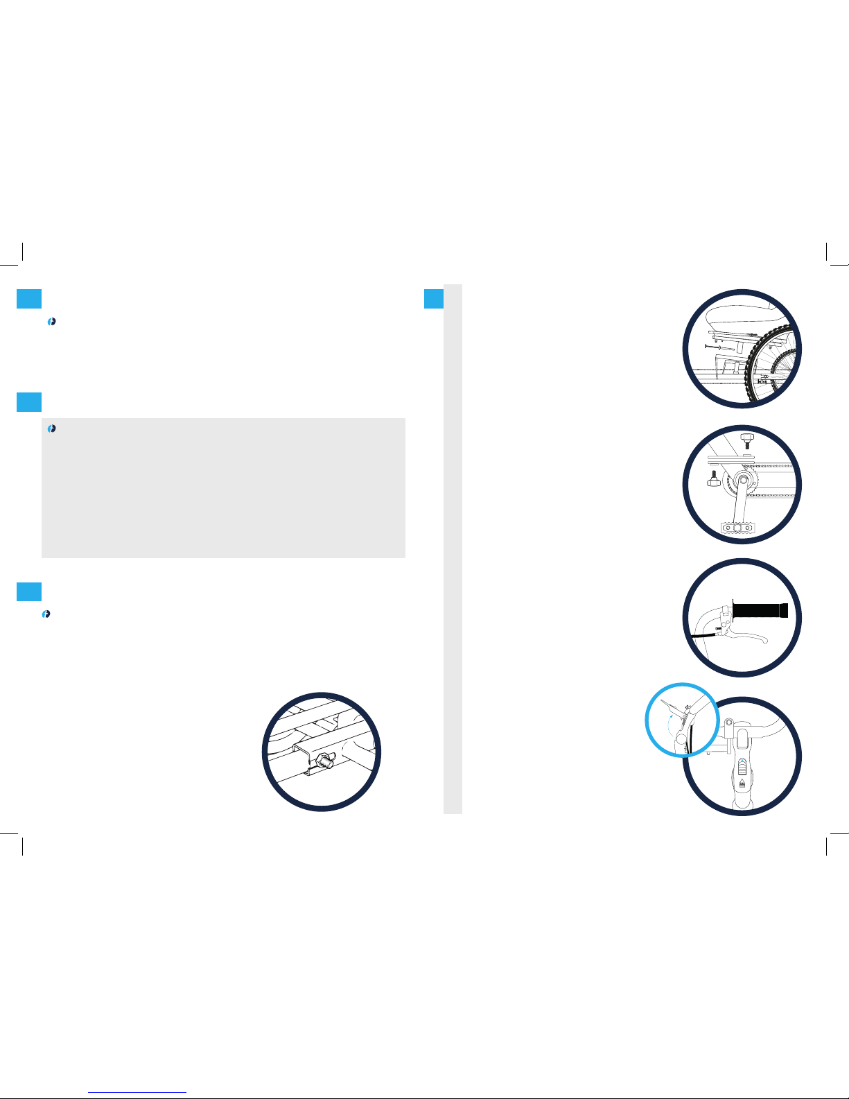
3. CHAIN: To fit the chain, place it into the front chainring and then
fit onto the rear cog. If you are unable to fit the chain fully onto
the rear cog then place as much chain onto the teeth of the cog
as possible and then turn the rear drive wheel (rear le) which
will feed the chain onto the cog.
4. ATTACHING FRONT WHEEL/FORK TO REAR TRIKE
The frame folding mechanism enables the tricycle to be split
into 2 parts for storage and transportation (see diagram 2). To
join the parts together, remove the black knob and washer from
the front section and the black knob with the threaded stud and
washer from the rear section. A kickstand is located on the Rear
Mainframe Unit and should be folded down at this stage. Bring
both halves together and re-attach the black knobs.
5. HANDLEBAR
These are already attached but will require moving to the
desired position for the rider. To adjust angle of handlebar,
slide the black button forwards and li lever at the same time
(see diagram 4). This enables both height and angle of
handlebar to be set. To lock in position simply depress lever.
6. CHAIN TENSION
To tension the chain, pull the Rear Unit back whilst holding the
Mainframe Unit as this will eectively stretch the chain. Located
beneath the 2 Stud Lock Nuts is a threaded screw that acts as a
chain tensioner. By threading the screw inwards it will gradually
put more tension on the chain. Continue until chain has approx.
1/4” slack in the middle. Finally tighten the two M12 Stud Lock
Nuts with a ¾ or 19mm wrench. Turn the pedal to ensure that
the chain is running smoothly.
7. CHAINGUARD
The plastic chain guard is pre-drilled and should be fixed to the
trike using the self-tapping screws which you will find attached
to the frame. Once fitted then thread on Right Hand pedal and
tighten securely.
8. SEAT (see diagram 3)
Your Tracer seat locates onto the Mainframe Unit by means of
square peg. The security locking pin and lanyard should be
placed through the locating hole on the square peg. Pushing on
the seat lever much like an automobile, enables fore and a
adjustment of the seat.
9. KICKSTAND
The purpose of the kickstand is to assist assembly/disassembly
of the folding option. NOTE: Do not sit on the tricycle when
removing the front section of the tricycle as the kickstand is not
designed to support the riders weight.
10. REAR WHEELS
In some case it may be necessary, for packaging, to remove the
rear wheels. The rear wheels slide over the rear axle and are
held in place by an M12 Nylock Nut. Each wheel hub has a
circular hole with a small square key cut into the hub.
Embedded at each end of your Tracer axle is a corresponding
steel key. Align slot and keyway and slide onto the axle. NOTE:
each hub is recessed and should be facing outwards with the
thread of the axle showing. Attach the M12 Nylock Nut and
tighten until wheel runs freely.
Assembly diagram 1
diagram 5
diagram 2
diagram 3
diagram 4
This range of tricycles is designed for recreation and therapy of children with special needs. Riders must have fair
head and trunk control to operate the trike eectively.
The tricycle is chain driven and has a fixed gear arrangement which helps to promote muscle development and
coordination. Additional supports can be added to the tricycle to tailor it to each child’s needs.
THE USE OF A WELL FITTED CYCLE HELMET IS RECOMMENDED
Recommended Use
BE SURE TO READ AND CARRY OUT THE FOLLOWING BEFORE THE TRICYCLE IS USED
1. READ THE INSTRUCTIONS CAREFULLY AND KNOW HOW TO PROPERLY OPERATE ALL
STANDARD AND ACCESSORY EQUIPEMENT FURNISHED WITH YOUR TRICYLE.
2. MAKE SURE THAT THE SADDLE AND THE HANDLEBARS ARE POSITIONED TO
PROVIDE THE MAXIMUM SAFETY AND COMFORT.
3. BEFORE RIDING THE TRICYCLE, BE SURE THAT THE BRAKES ARE CORRECTLY
ADJUSTED AND FUNCTION PROPERLY. BE SURE TO TEST THAT YOUR TRICYCLE
OPERATES SAFELY AND THAT IT CAN BE BROUGHT TO A SMOOTH SAFE STOP.
4. WE RECOMMEND THE USE OF A CYCLE HELMET, IF ONE IS USED, BE SURE IT FITS
COMFORTABLY AND SECURELY AND DOES NOT IN ANY WAY INTERFERE WITH VISION
OR HEARING.
5. OUR TRIKES ARE DESIGNED WITH A LOW CENTRE OF GRAVITY, BROAD WHEELBASE,
AND AN ADJUSTABLE STEERING STOP TO MINIMISE THE RISK OF THEM TIPPING
OVER, HOWEVER, ALL TRIKES CAN BE TIPPED OVER. ENSURE THAT THE RIDER IS
PROFICIENT IN HANDLING THE TRICYCLE ESPECIALLY WHEN CORNERING. IT IS
BEST TO CORNER SLOWLY UNTIL CONFIDENCE IS GAINED IN HANDLING THE TRIKE.
6. CHECK TYRES FOR PROPER INFLATION PRESSURE AS INDICATED ON THE SIDEWALL.
7. ALL TRICYCLES ARE MADE AND ARE INTENDED FOR ONLY ONE PERSON TO RIDE,
SITTING PROPERLY ON THE SEAT.
8. MAKE SURE THAT ALL NUTS, BOLTS, AND SCREWS ARE SECURELY TIGHTENED.
9. THE MANUFACTURER IS NOT RESPONSIBLE FOR FAILURE, INJURY, OR DAMAGE
CAUSED BY IMPROPER COMPLETION OF ASSEMBLY OR IMPROPER MAINTENANCE
AFTER SHIPMENT.
10. SINCE NORMAL WEAR OF SUCH PARTS AS TYRES, TUBES, BRAKE BLOCK
ASSEMBLIES, CABLES, ETC. WILL NECESSITATE REPLACEMENT FROM TIME TO TIME.
PLEASE REFER TO YOUR DEALER OR A REPUTABLE BICYCLE SHOP FOR WHATEVER
ITEMS ARE REQUIRED.
11. INSURE YOUR TRICYCLE
12. RETAIN THESE INSTRUCTIONS IN A SAFE PLACE FOR FUTURE REFERENCE.
FRONT FORK UNIT: This unit comprises a quick release front
wheel with MTB Disc Brake, V-Brakes, mudguard, handlebar and
multi adjustable handle bar stem.
MAINFRAME: This is the central frame of the tricycle and comprises
the Bottom Bracket (cartridge type) assembly, Headset Bearing
assembly. Some models of the tricycle are fitted with a Frame
Folding mechanism that allows the mainframe to be separated into
two sections.
REAR UNIT:Thus section carries the rear axles and comprises of a
drive axle and wheel, free axle and wheel, axle bearings and rear
drive cog.
M12 FRAME STUD NUTS (SEE DIAGRAM 1): These are located to
the rear of the mainframe and are used to connect the Mainframe
and Rear Unit.
CHAIN TENSION: Directly beneath the Ml2 Frame Stud Nuts is a
chain tension screw that should be adjusted to reduce slack on
your chain. There should only be approx. 1/4" slack on the chain.
PARKING BRAKE: The Tracer is fitted with two brakes, both
operating on the front wheel. One lever will operate the V-Brake
whilst the other lever operates the front disc brake on the le side
of the wheel. Your Tracer tricycle also has a locking brake lever to
immobilise the tricycle during transfer on/o. To operate pull the
brake lever whilst pushing down on the silver button, until
engaged. To release simply pull on the brake lever (see diagram 4).
WHEELS: The Tracer has a20" x2.125 Front wheel and two 24"
x2.125 Rear wheels. Tracer Junior models have three 20" x2.125"
wheels. The le rear wheel is the Drive Wheel. The right rear wheel
is the Free Wheel.
STEERING STOP: A steering limitation device is fitted to each
tricycle and can be found just above the front mudguard (socket
cap screw) on the Tracer tricycle.
PEDALS: All Tracer models as standard have Self Balance Pedals
fitted together with toe clip & strap. Optional pedal supports can
be supplied.
TOOLS: 1 x 41516 Allen key and I x Inflator (no inflator supplied if
puncture proof tyres fitted)
Standard Frame Features
Owners Responsibility
Table of contents
Other Theraplay Bicycle manuals


