Theraplay IMP User manual
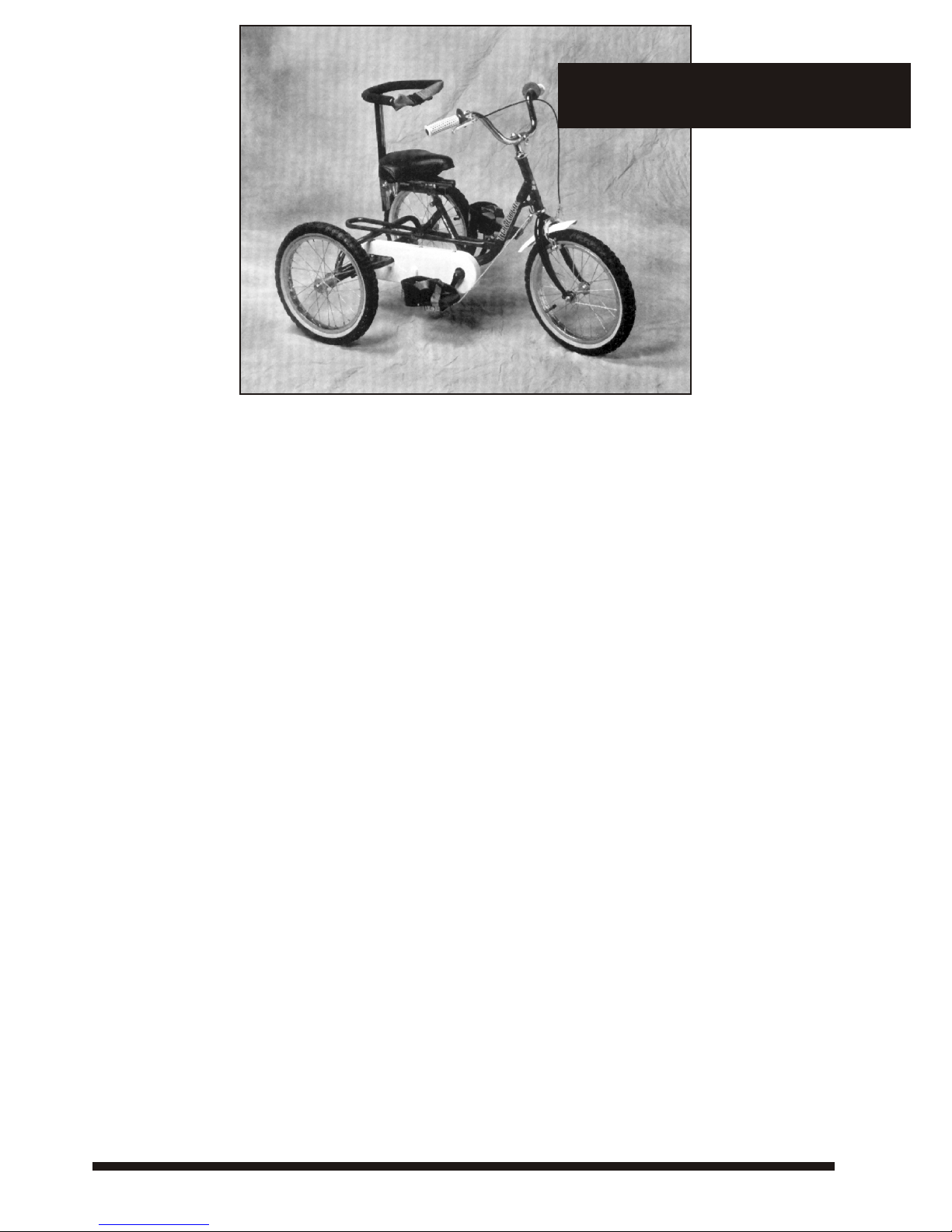
TRICYCLES
IMP - TERRIER - TMX - TRACKER
Congratulations!
Recommended Use
OWNER'S RESPONSIBILITY
BE SURE TO READ AND CARRY OUT THE FOLLOWING BEFORE THETRICYCLE IS USED
THE USE OF AWELL FITTED CYCLE HELMET IS RECOMMENDED
You have made an excellent investment in your child's health and happiness.Our tricycles offer
valuable exercise and therapy by providing cardiovascular fitness and increased muscle strength.
This range of tricycles is designed for recreation and therapy of children with special needs.Riders
must have fair head and trunk control to operate the trike effectively.
The tricycle is chain driven and has a fixed gear arrangement which helps to promote muscle development and
coordination.Additional supports can be added to the tricycle to tailor it to each child's needs.
The following instructions will give you advice on the adjustments and maintenance procedures to enable you to keep your
tricycle in the best possible condition.We do,however, recommend that a regular service is carried out by your appointed
dealer or a reputable local bicycle shop.The small cost will help to ensure rider safety and long life of the tricycle.
Please keep this manual in a safe place for future reference.
1. READ THE INSTRUCTIONS CAREFULLY AND KNOW HOW TO PROPERLY OPERATE
ALL STANDARD AND ACCESSORY EQUIPMENT FURNISHEDWITH YOUR TRICYCLE
2. MAKE SURE THAT THE SADDLE AND THE HANDLEBARS ARE POSITIONED TO
PROVIDE THE MAXIMUM SAFETYAND COMFORT.
3. BEFORE RIDING THE TRICYCLE, BE SURE THAT THE BRAKES ARE CORRECTLY
ADJUSTED AND FUNCTION PROPERLY. BE SURE TO TEST THAT YOUR TRICYCLE
OPERATES SAFELY ANDTHAT IT CAN BE BROUGHTTOA SMOOTH SAFE STOP.
4. WE RECOMMEND THE USE OF A CYCLE HELMET, IF ONE IS USED, BE SURE IT FITS
COMFORTABLY AND SECURELY AND DOES NOT IN ANY WAY INTERFERE WITH
VISION OR HEARING.
5. OUR TRIKESARE DESIGNED WITHA LOW CENTRE OF GRAVITY, BROADWHEELBASE,
AND AN ADJUSTABLE STEERING STOPTO MINIMISETHE RISK OF THEMTIPPING OVER,
HOWEVER, ALL TRIKES CAN BE TIPPED OVER. ENSURE THAT THE RIDER IS
PROFICIENT IN HANDLING THE TRICYCLE ESPECIALLY WHEN CORNERING. IT IS
BEST TO CORNER SLOWLY UNTIL CONFIDENCE IS GAINED IN HANDLING THE
TRIKE.
6. CHECK TYRES FOR PROPER INFLATION PRESSURE AS INDICATED ON THE SIDEWALL.
7. ALL TRICYCLESARE MADE AND ARE INTENDED FOR ONLY ONE PERSONTO RIDE,
SITTING PROPERLY ON THE SEAT.
8. MAKE SURE THAT ALL NUTS,BOLTS,AND SCREWS ARE SECURELY TIGHTENED.
9. THE MANUFACTURER IS NOT RESPONSIBLE FOR FAILURE, INJURY, OR DAMAGE
CAUSED BY IMPROPER COMPLETION OFASSEMBLY OR IMPROPER MAINTENANCE
AFTER SHIPMENT.
10. SINCE NORMAL WEAR OF SUCH PARTSAS TYRES,TUBES,BRAKE BLOCK ASSEMBLIES,
CABLES, ETC.WILL NECESSITATE REPLACEMENT FROMTIME TO TIME,PLEASE REFER
TO YOUR DEALER OR A REPUTABLE BICYCLE SHOP FOR WHATEVER ITEMS ARE
REQUIRED.
11. INSURE YOUR TRICYCLE
12. RETAINTHESE INSTRUCTIONS IN A SAFE PLACE FOR FUTURE REFERENCE.
• USE UNDER SUPERVISION
• THE RIDER SHOULD WEAR PROTECTIVE HEADGEAR AND ALWAYS WEAR SHOES
• DO NOT USE NEAR STEPS,SLOPING DRIVEWAYS, ROADWAYS,OR SWIMMING POOLS
• ALTHOUGH OUR PRODUCTS ARE DESIGNEDWITH SAFETY IN MIND,WE CANNOT
GUARANTEE FREEDOM FROM INJURY. THE USERASSUMES ALL RISK OF INJURY OR
SUITABILITY FOR A PARTICULAR CLIENT.
SAFETY CONSIDERATIONS
Owner’s Manual
YOUR NEW TRICYCLE
The IMP, Terrier,TMX andTracker models are designed to grow with
the rider.Saddle and handlebar adjustments combine with low fixed
gearing to ensure that each tricycle will give many years of fun and
exercise.
Front Fork Unit:
This unit comprises of; front wheel, fork,brake, mudguard, handlebars and
stem.
Mainframe:
This is the central frame of the tricycle and it comprises of; Bottom
Bracket assembly, and Headset Bearing assembly. Some models of the
tricycle are fitted with a Frame Folding Mechanism which allows the
Mainframe to be separated into two sections.
Rear Unit:
This section carriers the rear axles and comprises of;drive axle and wheel,
free axle and wheel, axle bearings and rear drive cog.
M12 Frame Stud Nuts (See Diagram 2):
These are located to the rear of the Mainframe and are used to connect
the Mainframe and Rear Unit.
M8 Frame Cap Screw (See Diagram2)
This is located to the rear of the Mainframe and is used to connect the
Mainframe and Rear Unit.
Parking Brake:
A caliper brake is fitted to all ourTricycles except theTracker model which
has a ‘V’ type brake fitted. AllTricycle models, with the exception of the
Imp, have a locking brake lever. To operate pull the brake lever whilst
pushing down on the silver button,until engaged. To release simply pull on
the brake lever.
Wheels:
The Imp has 12 ½" x 2 1/4" Wheels,The Terrier has 16" x 2.125 Wheels,
TMX has 20" x 2.125Wheels andTheTracker has 24" x 2"Wheels. The left
rear wheel is the DriveWheel.The right rear wheel is the FreeWheel.
Steering Stop:
A steering limitation device is fitted to each tricycle.
Optional Equipment
If you have ordered any of the following accessories please ensure that they have
been included. If any of the parts are missing,contact the customer help line.
Adjustable Back/Trunk Support
This item provides greater sitting stability. It has a U-shaped frame with a
waist strap.It is adjustable in height and depth.
Footsandals c/w Pulley System:
Designed to provide assistance in keeping feet on the pedals.The pulley
system helps to maintain the foot in a comfortable position.
Comfi-Grip Handlebar:
A multi adjustable handlebar made in 2 separate halves thus allowing any
number of set -up options.
Looped Handlebar:
Oval shaped handlebar allowing different hand grasp position over
conventional type handlebars.
Frame Folding Mechanism:
This item permits the front section of the frame to be folded or detached
from the rear for storage or transportation.
Pelvic Strap:
An addition strap which is used in conjunction with a Back/Trunk Support
to provide a greater degree of positioning support.
Rear Steering Mechanism:
Allows complete parent/carer control of the tricycle by means of a rear
mounted pole which controls steering of the tricycle.
Not available onTracker model.
Leg Calipers:
Attachment which is used in conjunction with Footsandals to prevent the
scissoring action of legs.
Push/Pull Bar:
This is a detachable guidance pole which can be fitted to the rear of the
tricycle for control or the front for steering.
‘In-Line’Trunk Support:
A trunk support which provides maximum positioning control. It has
adjustable wings which swingaway for transfer.
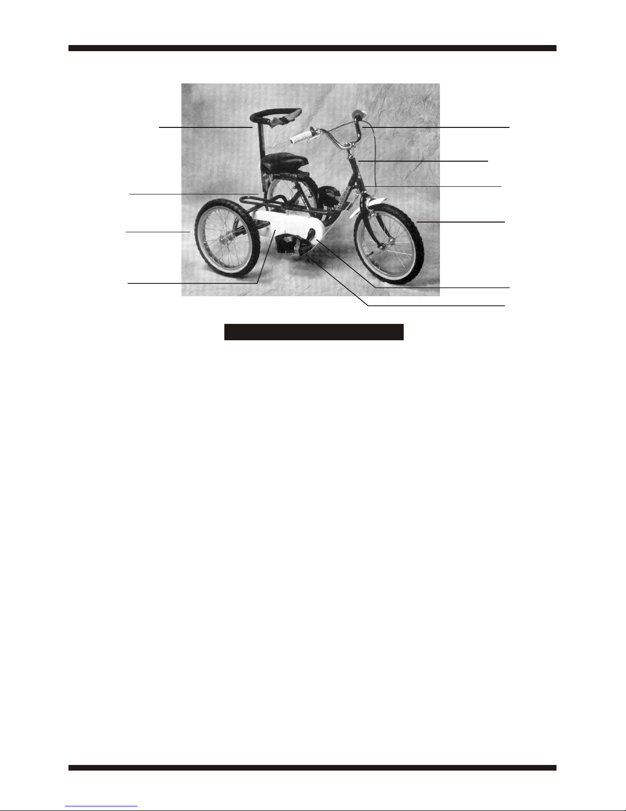
DIAGRAM 1
Back/Trunk Support Handlebars
Steering Column
Steering Stop
Front Wheel
Crank Arm
Foot Sandals
Drive Wheel
Free Wheel
Chain Guard

Rear Unit
Frame Studs
Mainframe
M8 frame
cap screw
M12 frame
stud nuts
DIAGRAM 2


DIAGRAM 3
YOURTRICYCLE COMES PARTIALLYASSEMBLED AND IF BOXED
REQUIRES ONE OR MORE OFTHE FOLLOWING STEPS.
1. Carefully remove the polythene wrapping using a sharp knife and
any other packaging material. Care should be taken not to damage
the upholstery,tyres and paintwork.
2.The tricycle mainframe is split into two parts; the Mainframe Unit
and the Rear Unit (see Diagram 2). To assemble these parts first
remove the M8 cap screw from the Mainframe Unit using the allen
wrench provided and then slide this fully into the Rear Unit.Refit the
M8 cap screw but do not tighten anything at this stage.
*We recommend that before attempting the next stages you protect
your clothes and floorcovering as this part contain grease*
3. CHAIN: To fit the chain, place it onto the front chainring and then
fit it onto the rear cog.If you are unable to fit the chain fully onto the
rear cog then place as much chain onto the teeth of the cog as
possible and then turn the rear drive wheel (rear left) which will feed
the chain onto the cog.
4A. ATTACHING FRONTWHEEL/FORK TO REAR OFTRIKE (IMP
AND TERRIER MODELS ONLY) (See Diagram 3):To attach front
wheel and fork to the rear of tricycle, first remove the two lock nuts
at the top of the threaded steering column. Leave one set of ball
bearings at the base of the steering column. Insert front wheel and
fork upwards into front of tricycle. Fit the other set of ball bearings
over the steering column with the ball bearings facing downwards and
replace locknuts on the threaded column,the broad flat lock nut first,
followed by the spacer washer (if fitted) and the smaller lock nut.
Tighten until the steering can be turned easily. Overtightening will
make the steering stiff.
4B. ATTACHING FRONT WHEEL/FORK TO REAR OF TRIKE
(FRAME FOLDING MODELS ONLY):The frame folding mechanism
enables the Tricycle to be split into 2 parts for storage and
transportation.To join the parts together,remove the black knob and
washer from the front section and the black knob with the threaded
stud and washer from the rear section.Bring both halves together and
reattach the black knobs.
5. HANDLEBARS: Fit the Handlebars and stem into the Steering
Column and secure with theAllen key bolt at the top of the Handlebar
Stem. Swing the Handlebars into desired position and secure with the
Allen key bolt on the underside of the Handlebar Stem. The
Handlebars are height adjustable. HINT: Loosen the bolt and then tap
the bolt head, this will dislodge the locking mechanism, then secure
tightly in place.
6. CHAINTENSION (See Diagram 2): To tension the chain, pull the
Rear Unit back whilst holding the Mainframe Unit, this will effectively
stretch the chain. Tighten the M8 Frame Cap Screw with the allen
wrench and then securely tighten the M12 Frame Stud Nuts with a 3/4
or 19MM wrench.Turn the pedal to ensure that the chain is running
smoothly. The chain tension is correct when the chain has 1/4” of slack
in the middle.
7. CHAIN GUARD: The plastic chainguard is pre-drilled and should be
fixed to the trike using the self tapping screws which will be attached to
the frame.
ASSEMBLY
Small lock nut
Broad flat lock nut
Ball Bearings
Collar
Front Fork

MAINTENANCE
8. SADDLE: Fit the saddle into the seat post and secure with the
locking lever/nut.The saddle is height adjustable but should NOT be
extended further than the marker hole on the seat post.The correct
saddle height should allow for a slight bend at the knee,when the ball
of the foot is on the pedal at its lowest position.The saddle can also be
moved horizontally along the seat post or tilted backwards or
forwards. The clamp located under the saddle controls this
movement.
9. BACK/TRUNK SUPPORT: If your tricycle is supplied with this
accessory this unit slides into the square location tubing and secures
beneath the saddle.This may be adjusted in depth.The trunk support
can be moved vertically.This must be secured in place with the M8
Cap Screws.
10. FOOTSANDALS WITH PULLEY SYSTEM: If your tricycle is
supplied with this accessory all fittings are provided.Secure with nuts
and plate to the underside of the pedal.The pulley wheel should be
attached to the frame hook.The cord runs through the pulley wheel
and is secured to the underside of each footsandal.The cord can be
adjusted in length to suit the riders requirements or removed.
11. KICK STAND: This is fitted to TMX and Tracker tricycles with
folding frame option. NOTE: Do not sit on tricycle when removing
the front section of the tricycle as the kick stand is not designed to
support the riders weight.The purpose of the kick stand is to assist
assembly/disassembly of the folding option.
Our products are designed to require the minimum of maintenance:
however the following maintenance procedures will help to ensure
the safe and efficient operation of the tricycle.
1 HAND BRAKES
Squirt a few drops of oil on pivot and hand lever. Do not wax or oil
rim.Always ensure that your brake blocks are free from oil or grease
and regularly check them for wear. If brake blocks are worn they
should be replaced.When fitting new brake blocks, ensure that they
are the right way up,(narrow edge to the top of the rim nearest to the
tyre).Apply the brakes and position the blocks so that they hit the rim
squarely and tighten.
2 CONTROL CABLES
Remove cable from the casing and grease inner cable.Replace worn
or damaged cables. Do not kink cables.Cables stretch with use, so
regular adjustment is necessary.
3 BEARING ADJUSTMENTS
Head bearings - Keep tight and well lubricated.The handlebars must
turn freely without any side to side play. Bottom Bracket bearings -
The crank assembly should turn freely without side to side play. Keep
the locknut tight and ensure the bearings are clean and well adjusted.
NOTE: if the Bottom Bracket bearings are not maintained this can
result in the chain becoming loose and may result in the Bottom
Bracket axle having to be replaced.
4 WHEEL ADJUSTMENTS
Front Wheel - Keep axle nuts tight.There should be no side to side
play and the wheel should run smoothly.Adjustments can be made by
tensioning or loosening the axle cones.The wheel should be centred
in the fork and sitting securely in the fork drop-out.Ensure spokes are
tight and the wheel is properly aligned.
DriveWheel (Riders left hand rear wheel) -This wheel is connected
to the axle by an internal thread. This wheel is secured in place with a
M14 Nyloc nut which has been cross drilled and pinned.Ensure that
the pin is completely removed before attempting to remove the
wheel nut and wheel. Ensure that the spokes are tight and the wheel is
properly aligned.
FreeWheel (Riders right hand rear wheel) -This wheel rotates on the
axle.The wheel and axle are secured in place by M12 Nyloc Nuts. If
there is side to side movement on this wheel,this can be eliminated
by tightening the M12 lock nuts. Ensure that the spokes are tight and
the wheel is properly aligned.


5 CRANKARMS
The crank arms are fixed onto the Bottom Bracket Axle by cap
Screws, these are located under the black plastic cap on the crank
arm. Ifeither crank feels loose,tighten securely with the M6Allen key
provided. NOTE: Failure to maintainthe crank arms can result in the
crank arms and the Bottom Bracket axlebeing damaged.
6 PEDALS
Each pedal has a different thread. Forcing the wrong pedal into the
wrong crank arm will destroy the threads in the crank arm.To prevent
this error, insert the“L” marked pedal into the left crank arm and“R”
into the right.Then tighten securely with the wrench.
NOTE:Left and Right are determined from the riding position on the
tricycle. Pedal sandals if fitted should be tightened against pedals using
the brackets and nuts.The brackets fit to the underside of the pedals
and they should be securely tightened in place.
7 CHAIN(See Diagram 2)
It is recommended that a 3 in 1 or similar oil is used to lubricate the
chain. Ensure that the chain is properly tensioned,if there is more than
1/4" slack in the middle of the chain then it needs tensioned. This can
be achieved by loosen the M12 Nyloc Frame Stud Nuts and the M8
Frame Cap Screw and then pulling the mainframe and rear axle in
opposite directions and then tighten the M12 lock nut and M8 screw.
Care should be taken not to overtighten the chain as this will make
the tricycle difficult to pedal.
8 HANDLEBARS
Ensure that the handlebars and handlebar stem are securedtightly.It is
dangerous to ride a tricycle if either is not properly secured. Do not
adjust handlebars beyond the maximum mark.
9 SADDLE
Ensure the seat pillar is secured tightly.The saddle should sit squarely
on the seat pillar and should not be extended beyond the maximum
marker hole.
10 TYRES
Check tyres for proper inflation pressure as indicated on the sidewall.
If the tyre is worn or the inner tube is punctured,repairs can be made
to the rear wheels without removing the wheel from the axle. The
front wheel will need to be removed from the front fork.
11 POSITIONING SUPPORT
Ensure that all positioning supports are properly secured.All screws
should be tightened.
12 PULLEY CORD
The footsandal pulley cord is madeof nylon.Should the cord start to
wear, heat slowly with a match or candle, until the cord bonds
together. Do not overheat or the cord will melt. Regular checks
prolong the life of the cord. Ensure that it is running freely through
the pulley wheel.A siliconespray ensures a smootheroperation.
13 ADJUSTABLE STEERING STOP
Ensure that this is adjusted to suitthe riders ability.
MAINTENANCE INTERVALS
Keep all painted parts cleaned andwaxed for a long lasting lustre.
B1 -WEEKLY
• Spray all chrome parts with aprotective spray.
• Lubricate the following: Pivot bolt on brake lever
Top of bolt on caliper brake
Inside bearing on both pedals
Chain-turn pedal crank and spray freely
Axle drive cog and axle
• Check tyre pressure
• Check for loose bolts and nuts
• Crank arms
3-6 MONTHS
• Check tyres for wear
• Check wheel alignment and for loose spokes
• Check brakes for adjustment,worn cable and worn brake blocks
• Clean and adjust all bearings and cones
• Check chain for adjustment and grime
• Check for loose bolts and nuts
• Check FreeWheel for excessive side-to-side movement
• Check DriveWheel for slippage
WARNING! Like any mechanical device, a tricycle and its
components are subject to wear and stress. Different materials and
mechanisms wear or fatigue at different rates and have different life
cycles. If a component's life cycle is exceeded, the component can
suddenly fail, causing serious injury. Scratches, cracks and
discolouration are signs of stress-caused fatigue and indicate that a
part is at the end of its useful life andneeds to be replaced.
USA GREAT BRITAIN
TRIAID Inc
PO Box 1364
Cumberland
MD21501 - 1364
USA
Tel: 301 759 3525
Fax: 301 759 3525
www.triaid.com
THERAPLAY Ltd.
32 Welbeck Road
Darnley Ind. Est.
Glasgow
G53 7SD
Tel: 0141 876 9177
Fax: 0141 876 9039
This manual suits for next models
3
Table of contents
Other Theraplay Bicycle manuals


