Thermal Care FT Series Instruction Manual


This manual suits for next models
5
Table of contents
Other Thermal Care Chiller manuals

Thermal Care
Thermal Care NQ Series User manual

Thermal Care
Thermal Care TSE Instruction Manual

Thermal Care
Thermal Care Accuchiller KSE Instruction Manual

Thermal Care
Thermal Care Accuchiller EQ Series User manual

Thermal Care
Thermal Care Accuchiller TCF Instruction Manual

Thermal Care
Thermal Care ACCUCHILLER EQ Instruction Manual

Thermal Care
Thermal Care Accuchiller MX Series Instruction Manual

Thermal Care
Thermal Care Accuchiller TCFW375 Instruction Manual
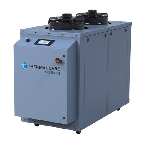
Thermal Care
Thermal Care Accuchiller NQ Series Instruction Manual
Popular Chiller manuals by other brands
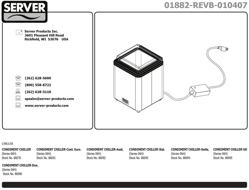
Server
Server 01882-REVB-010407 quick start guide

Trane
Trane Water-Cooled CenTraVac S Series installation instructions

Daewoo
Daewoo SDA2252 user manual
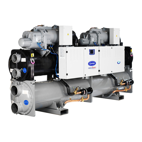
Carrier
Carrier 30XW user guide
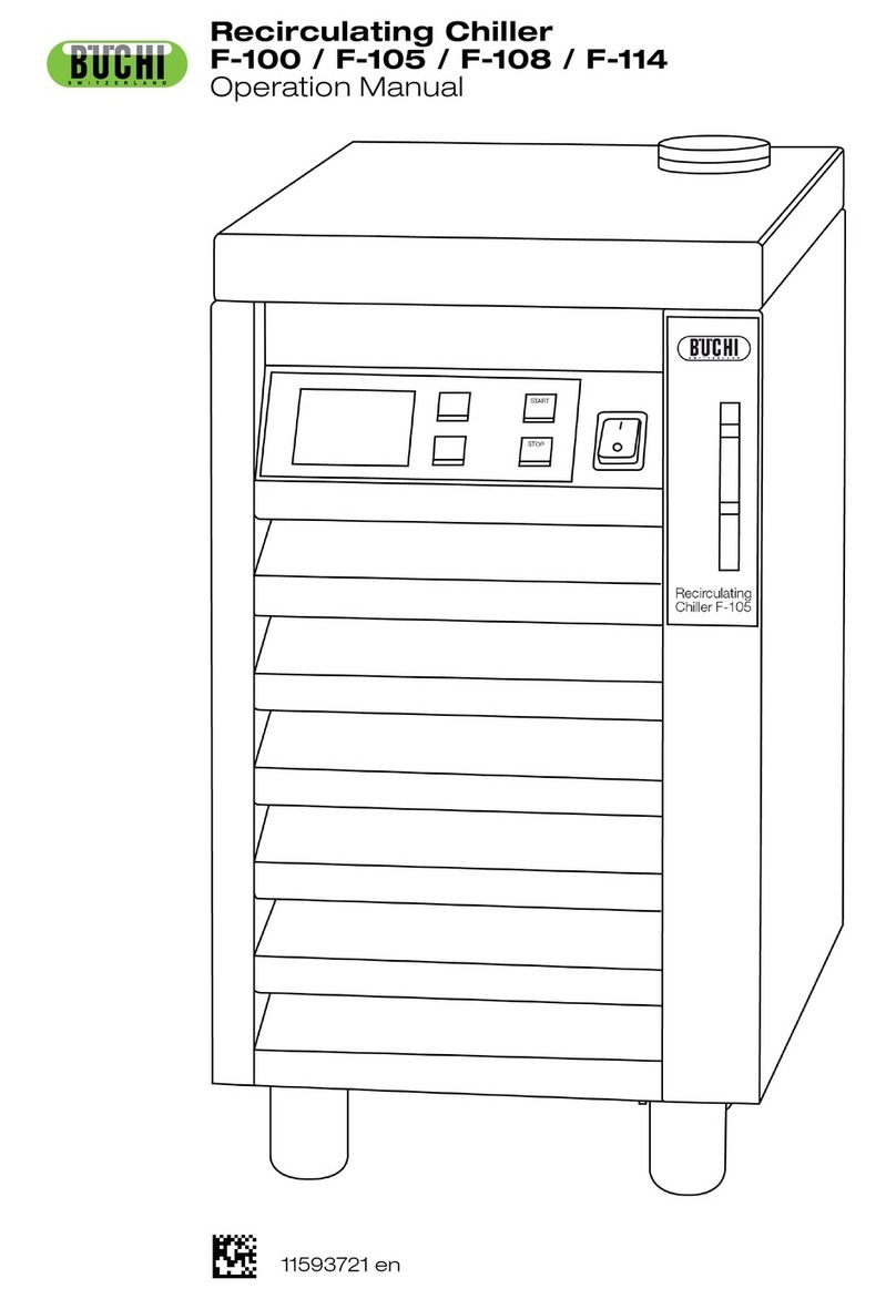
Buchi
Buchi F-108 Operation manual
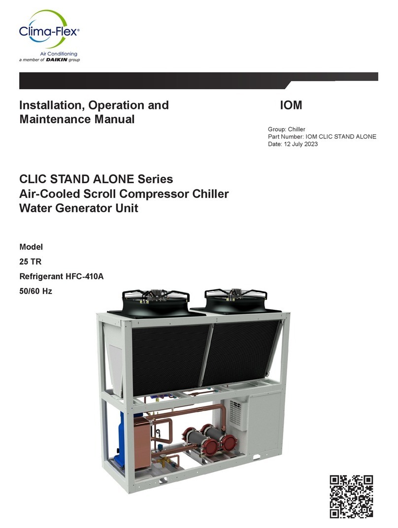
Daikin
Daikin Clima-Flex CLIC STAND ALONE Series Installation, operation and maintenance manual
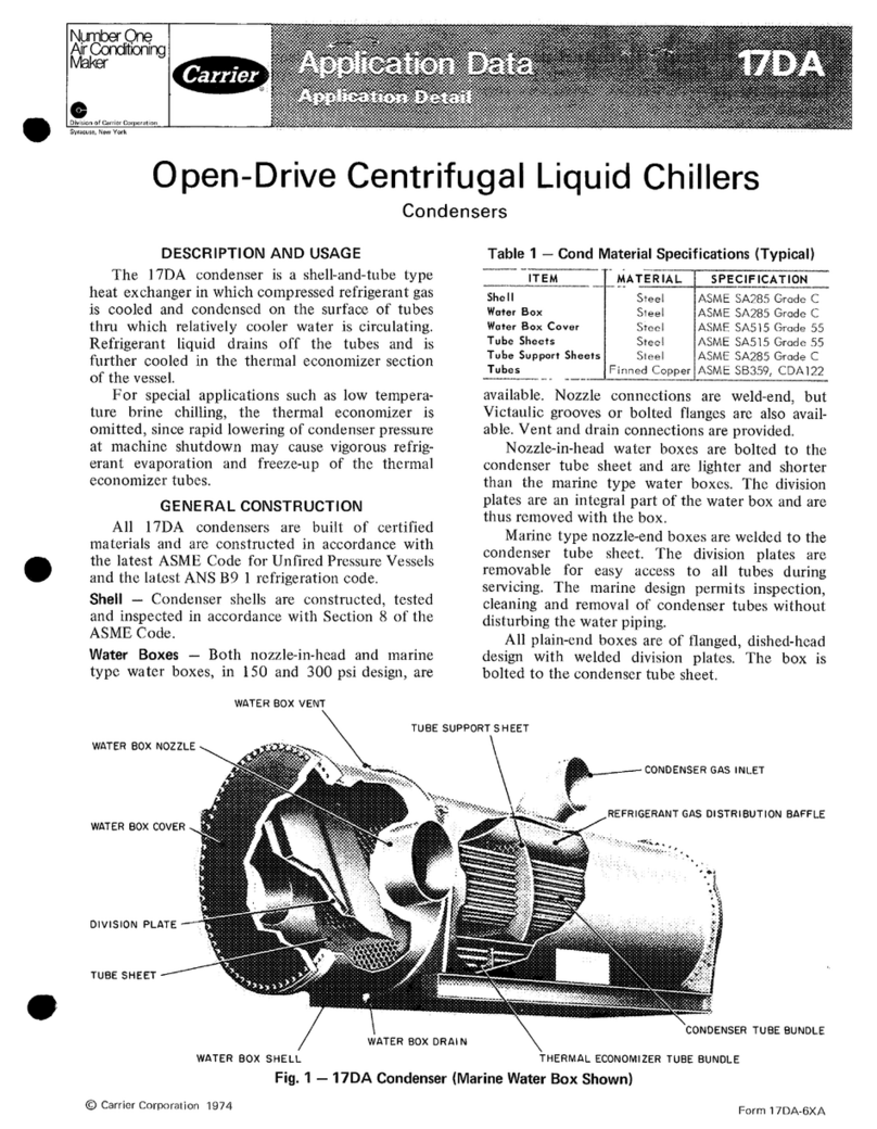
Carrier
Carrier 17DA Application data
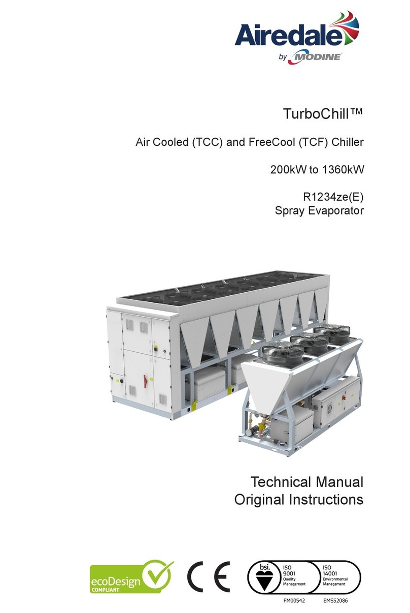
Modine Manufacturing
Modine Manufacturing Airedale TurboChill R1234ze manual
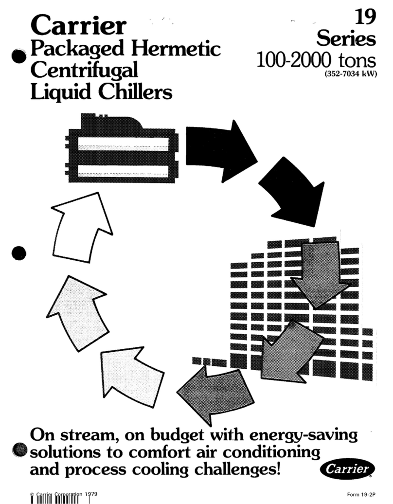
Carrier
Carrier 19 user manual

Carrier
Carrier 30HR Series Installation, Start-Up and Service Instructions
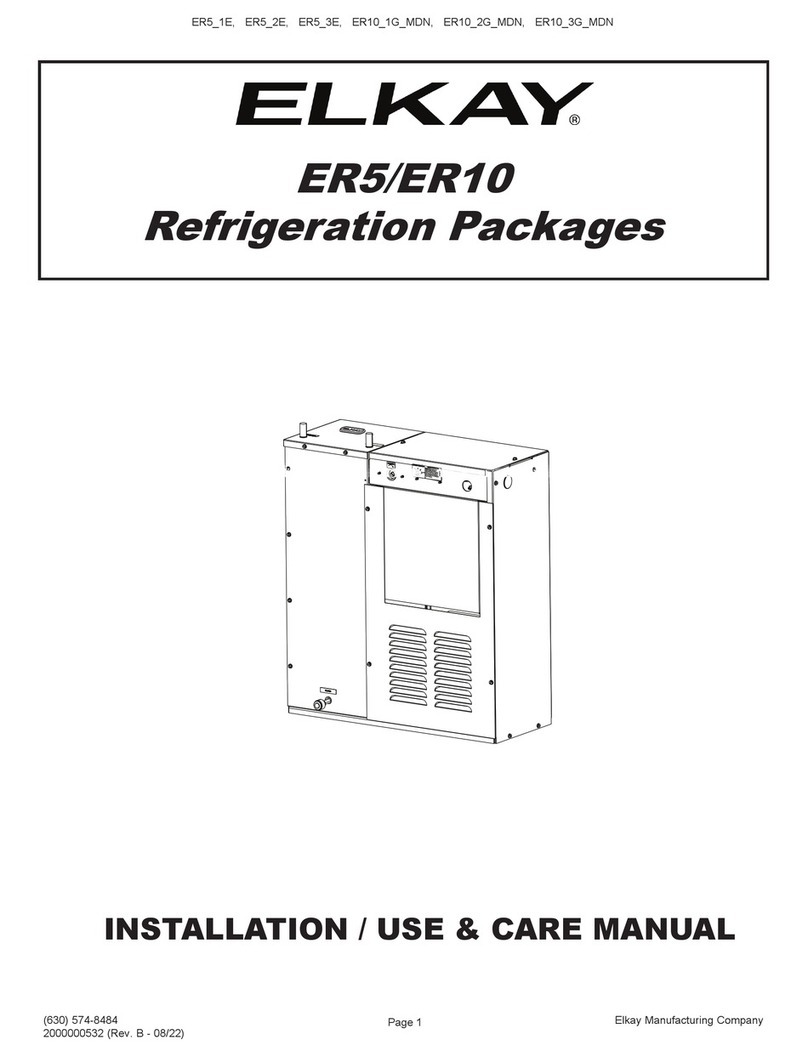
Elkay
Elkay ER5 Series Installation, use & care manual

Cleveland
Cleveland TCCT-60-CC supplementary guide
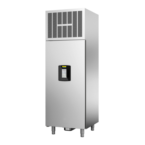
Nordcap
Nordcap SKF 18 GN 1/1 Installation
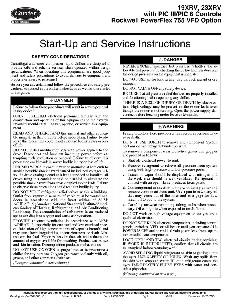
Carrier
Carrier AquaEdge 19XRV series Start-up and service instructions

Kaysun
Kaysun KEM-HT-65 DRS5 Owners & installation manual
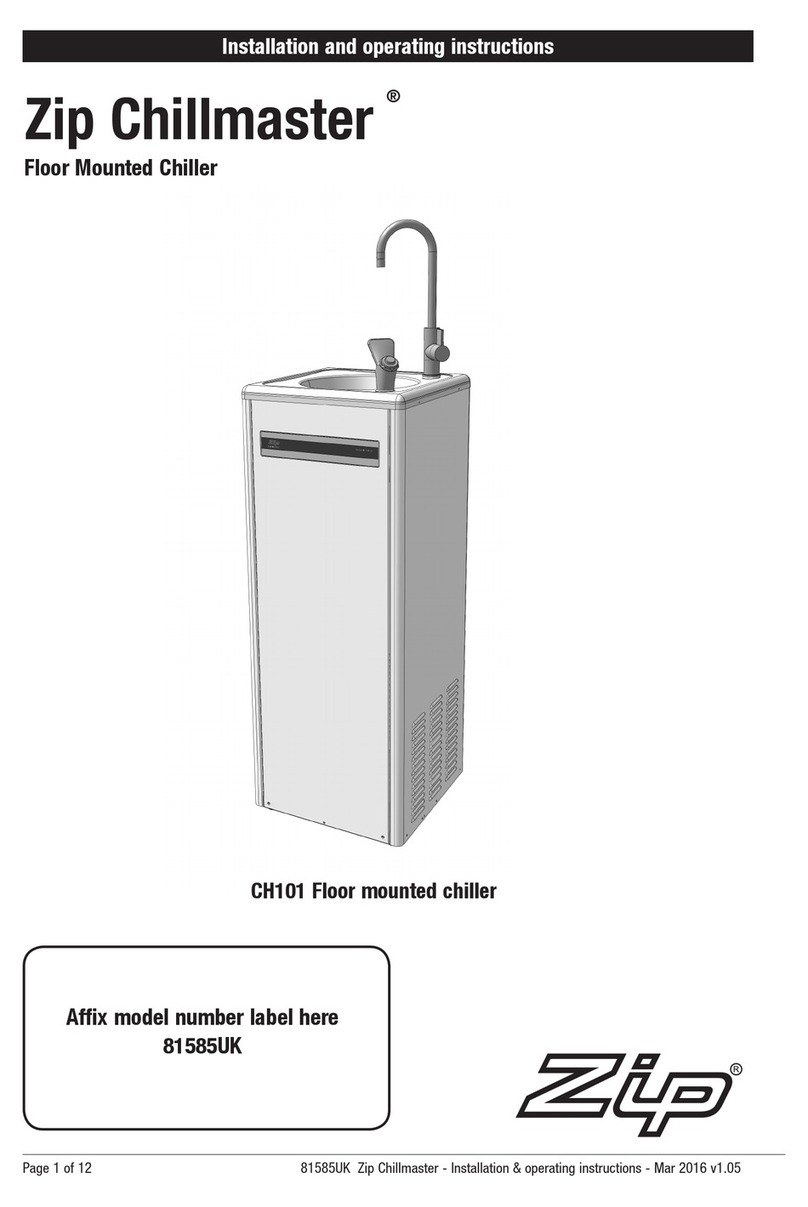
Zip
Zip CH101 Installation and operating instructions
Mueller
Mueller PMC 40/50 Instructions for installation and operation
SMC Networks
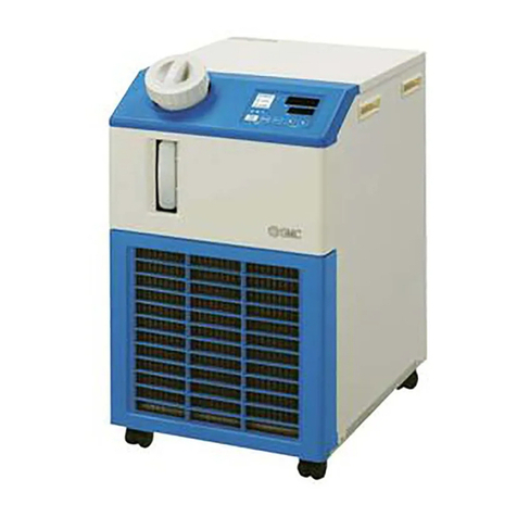
SMC Networks HRS012-A*-10-* Operation manual