Thermal Care Accuchiller EQ Series User manual

Installation & Operation Manual
EQ Series Portable and Remote Condenser Chillers

Page Intentionally Blank

Table of Contents
Foreword ...........................................................................................................................................................................1
Safety Guidelines .............................................................................................................................................................1
Pre-Installation.................................................................................................................................................................2
Receiving Inspection .......................................................................................................................................................................................2
Unit Storage........................................................................................................................................................................................................ 3
Installation - Chiller.........................................................................................................................................................3
Foundation..........................................................................................................................................................................................................3
Unit Location...................................................................................................................................................................................................... 3
Rigging ................................................................................................................................................................................................................. 3
Chilled Process Fluid Piping .........................................................................................................................................................................3
Condenser Water Piping................................................................................................................................................................................ 4
Installation –Remote Air-Cooled Condenser ..............................................................................................................4
Location................................................................................................................................................................................................................ 4
Lifting .................................................................................................................................................................................................................... 5
Mounting Legs ..................................................................................................................................................................................................5
Interconnecting Refrigerant Piping...........................................................................................................................................................5
Refrigeration Piping Design ......................................................................................................................................................................... 5
Determining Equivalent Line Length ........................................................................................................................................................ 7
Liquid Line Sizing.............................................................................................................................................................................................. 7
Discharge (Hot Gas) Line Sizing..................................................................................................................................................................7
Calculating Refrigerant and Oil Charge................................................................................................................................................... 8
Oil Charge Determination............................................................................................................................................................................. 8
Setting Condenser Fan Controls................................................................................................................................................................. 8
Installation - Electrical ....................................................................................................................................................9
Standard Controller Operation....................................................................................................................................10
Changing Temperature Display Scale ....................................................................................................................................................10
Diagnostic Error Codes.................................................................................................................................................................................12
SPI Communications Option......................................................................................................................................................................13
Start-Up...........................................................................................................................................................................15
Step 1 - Connect Main Power ...................................................................................................................................................................15
Step 2 - Fill Coolant Circuit.........................................................................................................................................................................15
Step 3 - Check Condenser ..........................................................................................................................................................................16
Step 4 –Check Refrigerant Valves...........................................................................................................................................................17
Step 5 –Verify Freezestat Setting ............................................................................................................................................................17
Step 6 –Turn On Control Power ..............................................................................................................................................................17
Step 7 –Establish Coolant Flow................................................................................................................................................................17
Step 8 –Intial Unit Operation....................................................................................................................................................................17
Preventive Maintenance ...............................................................................................................................................18
Once a Week ....................................................................................................................................................................................................18
Once a Month..................................................................................................................................................................................................18
Every Three Months.......................................................................................................................................................................................18
Preventive Maintenance Checklist ..............................................................................................................................19
General Troubleshooting..............................................................................................................................................20
Drawings .........................................................................................................................................................................20
Warranty .........................................................................................................................................................................21

Page Intentionally Blank

1
Foreword
The portable chiller is a packaged unit typically
consisting of a refrigeration circuit, coolant reservoir,
and pumping system in a cabinet. The purpose is to
provide cooling water or coolant for cooling an
industrial process.
This manual is to serve as a guide for installing,
operating, and maintaining the equipment. Improper
installation can lead to poor performance and/or
equipment damage. We recommend the use of
qualified installers and service technicians for all
installation and maintenance of this equipment.
This manual is for our standard product. The
information in this manual is general in nature. Unit-
specific drawings and supplemental documents are
included with the equipment as needed. Additional
copies of documents are available upon request. We
strive to maintain an accurate record of all
equipment during the course of its useful life.
Due to the ever-changing nature of applicable
codes, ordinances, and other local laws pertaining to
the use and operation of this equipment, we do not
reference them in this manual. There is no substitute
for common sense and good operating practices
when placing any mechanical equipment into
operation. We encourage all personnel to familiarize
themselves with this manual's contents. Failure to do
so may unnecessarily prolong equipment down time.
The equipment uses a hydro fluorocarbon (HFC),
trade named R-407c, as a chemical refrigerant for
heat transfer purposes. This chemical is sealed and
tested in a pressurized system containing ASME
coded vessels; however, a system failure will release
it. Refrigerant gas can cause toxic fumes if exposed
to fire. Place these units in a well-ventilated area,
especially if open flames are present. Failure to
follow these instructions could result in a hazardous
condition. We recommend the use of a refrigerant
management program to document the type and
quantity of refrigerant in the equipment. In addition,
we recommend only licensed and EPA certified
service technicians work on our refrigeration circuits.
Follow good piping practices and the information in
this manual to ensure successful installation and
operation of this equipment.
We trust your equipment will have a long and useful
life. If you should have any questions, please contact
our Customer Service Department specifying the
serial number and model number of the unit as
indicated on the nameplate.
Safety Guidelines
Observe all safety precautions during installation,
start-up, and service of this equipment. The
following is a list of symbols used in this manual and
their meaning.
General Warning
Electricity Warning
Sharp Element Warning
Hot Surface Warning
Flammable Material Warning
Explosive Material Warning
General Mandatory Action
Wear Eye Protection
Wear Protective Gloves
Wear Ear Protection
Disconnect Before Carrying Out Maintenance or
Repair
Connect an Earth Terminal to Ground

2
Only qualified personnel should install, start-up, and
service this equipment. When working on this
equipment, observe precautions in this manual as
well as tags, stickers, and labels on the equipment.
WARNING: Any use or misuse of this equipment
outside of the design intent may cause injury or
harm.
WARNING: Vent all refrigerant relief valves in
accordance to ANSI/ASHRAE Standard 15, Safety
Code for Mechanical Refrigeration. Locate this
equipment in a well-ventilated area. Inhalation
of refrigerant can be hazardous to your health
and the accumulation of refrigerant within an
enclosed space can displace oxygen and cause
suffocation.
WARNING: This equipment contains hazardous
voltages that can cause severe injury or death.
WARNING: This equipment contains refrigerant
under pressure. Accidental release of refrigerant
under pressure can cause personal injury and or
property damage.
WARNING: This equipment may contain fan
blades or other sharp edges. Make sure all fan
guards and other protective shields are securely
in place.
WARNING: The exposed surfaces of motors,
refrigerant piping, and other fluid circuit
components can be very hot and can cause burns
if touched with unprotected hands.
CAUTION: Disconnect and lock out incoming
power before installing, servicing, or
maintaining the equipment. Connecting power to
the main terminal block energizes the entire
electric circuitry of the unit. Shut off the electric
power at the main disconnect before opening
access panels for repair or maintenance.
CAUTION: Wear eye protection when installing,
maintaining, or repairing the equipment to
protect against any sparks, debris, or fluid leaks.
CAUTION: The equipment will exceed 70 dBA
sound pressure at 1 meter distance and 1 meter
elevation when operating. Wear ear protection
as required for personal comfort when operating
or working in close proximity to the chiller.
CAUTION: Wear protective gloves when
installing, maintaining, or repairing the
equipment to protect against any sparks, debris,
or fluid leaks.
Pre-Installation
Receiving Inspection
When the unit arrives, verify the information on the
unit nameplate agrees with the order
acknowledgement and shipping papers. Inspect the
equipment for any visible damage and verify all
items shown on the bill of lading are present. If
damage is evident, document it on the delivery
receipt by clearly marking any item with damage as
“unit damage” and notify the carrier. In addition,
notify our Customer Service Department and they
will provide assistance with preparing and filing
freight damage claims, including arranging for an
estimate on repair costs; however, filing the shipping
damage claim is the responsibility of the receiving
party. Do not install damaged equipment without
getting the equipment repaired.
Shipping damage is the responsibility of the carrier.
To protect against possible loss due to damage
incurred during shipping and to expedite payment
for damages, it is important to follow proper
procedures and keep records. Photographs of
damaged equipment are excellent documentation
for your records.
Start unpacking the unit, inspect for concealed
damage, and take photos of any damage found.
Once received, equipment owners have the
responsibility to provide reasonable evidence that
the damage did not occur after delivery. Photos of
the equipment damage while the equipment is still
partially packed will help in this regard. Refrigerant
lines can be susceptible to damage in transit. Check
for broken lines, oil leaks, damaged controls, or any
other major component torn loose from its
mounting point.
Record any signs of concealed damage and file a
shipping damage claim immediately with the
shipping company. Most carriers require concealed
damages be reported within 15 days of receipt of
the equipment. In addition, notify our Customer
Service Department and they will provide assistance
with preparing and filing freight damage claims,
including arranging for an estimate on repair costs;
however, filing the shipping damage claim is the
responsibility of the receiving party.

3
Chillers with an integral water-cooled or air-cooled
condenser ship with a full refrigerant charge. Chillers
designed for use with a remote air-cooled condenser
and the remote condensers themselves ship with a
nitrogen holding charge. Check the remote
condenser for signs of leaks prior to rigging. This will
ensure no coil damage has occurred after the unit
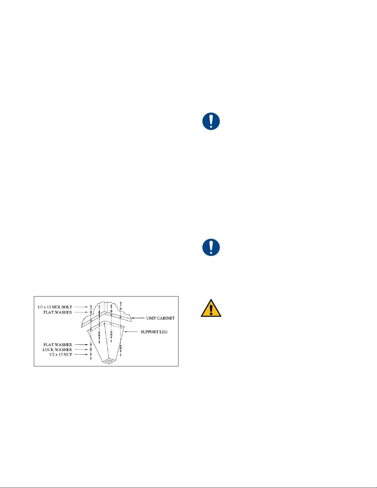
left the factory. The condenser ships with the legs
removed. Mount the legs to the condenser using the
provided nuts, bolts, and washers.
Unit Storage
If the chiller is stored prior to installation, it is
important to protect it from damage. Blow out any
water from the evaporator and water-cooled
condenser circuits to protect the unit from damage
from freezing. Close any open refrigerant valves.
Cover the equipment to keep dirt and debris from
accumulating on it. Units charged with refrigerant
should not be stored in areas warmer than 145°F.
Installation - Chiller
Foundation
Install the chiller on a rigid, non-warping mounting
pad, concrete foundation, or level floor suitable to
support the full operating weight of the equipment.
When installed the equipment must be level within
¼ inch over its length and width.
Unit Location
The chiller is available in many different
configurations for various environments. Refer to the
proposal and order acknowledgement document for
the equipment to verify the specific design
conditions in which it can operate.
Allow a minimum of 48 inches of clearance between
the chiller and any walls or obstructions. For
installations with multiple chillers, allow a minimum
of 96 inches between chillers placed side-by-side or
48 inches for chillers placed end-to-end.
When locating the chiller it is important to consider
accessibility to the components to allow for proper
maintenance and servicing of the unit. In general,
allow a minimum of 36 inches of clearance around
and above the unit. Avoid locating piping or conduit
over the unit to ensure easy access with an overhead
crane or lift to lift out heavier components during
replacement or service.
Proper ventilation is another important
consideration when locating the chiller. In general,
locate the unit in an area that will not rise above
110°F. In addition, ensure the condenser and
evaporator refrigerant pressure relief valves can vent
in accordance with all local and national codes.
Chillers with an integral air-cooled condenser require
a minimum of 36 inches of clearance at both the
condenser air inlet and condenser air discharge, they
are not, as standard, designed to have the condenser
air discharge ducted. Improper clearance or poor
ventilation will reduce the cooling capacity of the
chiller and may cause high refrigerant pressure
problems. In order to avoid possible low refrigerant
pressure safety trips during start-up, maintain the
inlet air temperature above 50°F. If outside air is
ducted into an indoor chiller with an integral air-
cooled condenser, there is an option for low ambient
heat pressure controls which allow for incoming air
temperatures down to 0°F. Cooler temperatures than
this require custom modifications.
Rigging
The chiller has a frame to facilitate easy movement
and positioning with a crane or forklift. Follow
proper rigging methods to prevent damage to
components. Avoid impact loading caused by
sudden jerking when lifting or lowering the chiller.
Use pads where abrasive surface contact may occur.
Chilled Process Fluid Piping
Proper insulation of chilled process fluid piping is
crucial to prevent condensation. The formation of
condensation adds a substantial heat load to the
chiller.
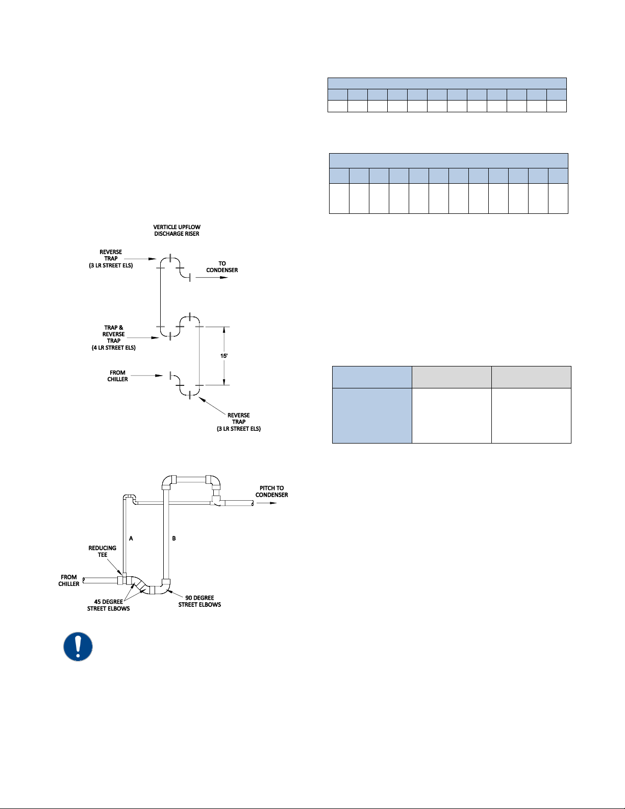
The importance of properly sized piping between
the chiller and process cannot be overemphasized.
See the ASHRAE Handbook or other suitable design
guide for proper pipe sizing. In general, run full size
piping out to the process and reduce pipe size at
connections as needed. One of the most common
causes of unsatisfactory chiller performance is poor
piping system design. Avoid long lengths of hoses,
quick disconnect fittings, and manifolds wherever
possible as they offer high resistance to water flow.
When manifolds are required, install them as close to
the use point as possible. Provide flow-balancing
valves at each machine to assure adequate water
distribution in the entire system. Typically, when

4
piping is overhead with a total run length over 90
feet there should be a valve in the supply line and an
inverted P trap with a vacuum break valve installed
as shown in Figure 1.
Figure 1 –Recommended Overhead Piping
All standard portable chillers include an internal
coolant pump and reservoir. Nominal coolant flow
rates assume a 10°F rise across the evaporator at
50°F set point and 85°F entering condenser water for
water-cooled chillers or 95°F entering air for integral
air-cooled or remote air-cooled condenser chillers.
Condenser Water Piping
(Water-Cooled Condenser Units Only) The
performance of a water-cooled condenser is
dependent on the flow and temperature of the
cooling water used. Insufficient cooling of the
condenser will result in the reduction of cooling
capacity of the chiller and under extreme conditions
may result in the chiller shutting down due to high
refrigerant pressure. Allowing the condenser to plug
up from contaminants in the condenser water
stream adversely affects performance. In order to
reduce maintenance costs and chiller downtime, a
water treatment program is highly recommended for
the condenser cooling water. Contact our Customer
Service Department for assistance in the proper
procedure for cleaning out any plugged condenser.
The nominal water-cooled condenser is design for
85°F condenser cooling water supply. Under normal
operation there will be about a 10°F rise through the
condenser resulting in 95°F exiting water. To ensure
proper water flow through the condenser, ensure the
condenser water pump provides at least 25 psi or
water at a flow rate of 3 gpm per ton of chiller
capacity.
Each condenser has a two-way condenser water-
regulating valve. The condenser water-regulating
valve controls the amount of water allowed to pass
through the condenser in order to maintain proper
refrigeration pressures in the circuit.
To prevent damage to the condenser and/or water-
regulating valve, the water pressure should not
exceed 150 psig.
Installation –Remote Air-
Cooled Condenser
Chillers designed for use with a remote air-cooled
condenser include a factory-selected remote
condenser. The remote air-cooled condenser
typically ships separately from a different location
than the chiller.
Location
The remote air-cooled condenser is for outdoor use.
Locate the remote condenser in an accessible area.
Allow a minimum of 48 inches of clearance between
the condenser and any walls or obstructions. For
installations with multiple condensers, allow a
minimum of 96 inches between condensers placed
side-by-side or 48 inches for condensers placed end-
to-end.
When locating the condenser it is important to
consider access to the components to allow for
proper maintenance and servicing of the unit. In
general, allow a minimum of 36 inches of clearance
around and above the unit. Avoid locating piping or
conduit over the unit to ensure easy access with an
overhead crane or lift to lift out heavier components
during replacement or service.
Proper ventilation is another important
consideration when locating the condenser. In
general, locate the unit in an area that will not rise
above 110°F.
Install the unit on a firm, level base no closer than its
width from walls or other condensers. Avoid
locations near exhaust fans, plumbing vents, flues, or
chimneys. Fasten the mounting legs at their base to
the steel or concrete of the supporting structure. For
units mounted on a roof structure, the steel support
base holding the condenser should be elevated
above the roof and attached to the building.
NOTE:
If piping is above chiller and exceeds 90 feet in total
length, install an inverted P-trap and vacuum break
valve in return line and add a check valve to the
supply line.
Check valve
1/2 inch vacum break valve
12 inches above highest
point in piping system
12 inches above highest point in
the piping system
½ inch vacuum
break valve
Check valve

5
Avoid areas that can create a “micro-climate” such as
an alcove with east, north, and west walls that can be
significantly warmer than surrounding areas. The
condenser needs to have unrestricted airways so it
can easily move cool air in and heated air away.
Consider locating the condenser where fan noise
and vibration transmission into nearby workspaces is
unlikely.
The unit ships on its side with the legs removed to
reduce shipping dimensions and provide more
protection to the coil from possible damage caused
by impact loading over rough roads and transit
conditions.
Lifting
Use only qualified personnel using the proper
equipment when lifting and positioning the
condenser. Lifting brackets or holes are at the
corners for attaching lifting slings. Use spreader bars
when lifting to apply the lifting force vertically.
Under no circumstances use the coil headers or
return bends in the lifting or moving of the
condenser.
Mounting Legs
Assemble the four corner legs to the bottom flanges
on the unit side panels and end panels using the
hardware provided and the matching mounting
hole-patterns. All corner legs are the same.
Figure 2 - Mounting Remote Condenser Legs
Interconnecting Refrigerant Piping
The chiller and remote condenser ship with a
nitrogen holding charge. Evacuation of this charge is
required before charging with refrigerant. The chiller
is for use only with the air-cooled condenser
provided with the unit. The following section covers
the required piping between the chiller and the
provided air-cooled condenser.
The discharge and liquid lines leaving the chiller
have caps. These line sizes do not necessarily reflect
the actual line sizes required for the piping between
the chiller and the air-cooled condenser.
Refrigerant piping size and piping design have a
significant impact on system performance and
reliability. All piping should conform to the
applicable local and state codes.
CAUTION: Use refrigerant grade copper tubing
ASTM B280 only and isolate the refrigeration
lines from building structures to prevent transfer
of vibration. All copper tubing must have a
pressure rating suitable for R-407c: tubing that is
¾” OD or larger must be Type K rigid tubing.
ACR annealed tubing coil may be used for sizes
⅝” ODS or smaller.
Do not use a saw to remove end caps. This might
allow copper chips to contaminate the system. Use a
tube cutter or heat to remove the caps. When
sweating copper joints it is important to evacuate all
refrigerant present and flow dry nitrogen through
the system. This prevents the formation of toxic
gases, corrosive acids, and scale.
CAUTION: Do not use soft solders. For copper-to-
copper joints use a copper-phosphorus braze
alloy (BCuP per the American Welding Society)
with 5% (BCuP-3) to 15% (BCuP-5) silver
content. Only use a high silver content brazing
alloy (BAg per AWS) for copper-to-brass or
copper-to-steel joints such as a 45% (BAg-5)
silver content. Only use oxy-acetylene brazing.
WARNING: The POE oil contained within the
compressor is hygroscopic and has the ability to
absorb water vapor from the atmosphere. Take
necessary steps to prevent an open system from
exposure to the atmosphere for extended periods
while installing the interconnecting refrigerant
tubing.
Refrigeration Piping Design
The system is configurable in any of the
arrangements as shown in Figure 3, Figure 4 and
Figure 5. The configuration and its associated
elevation, along with the total distance between the
chiller and the air-cooled condenser are important
factors in determining the liquid line and discharge
line sizes. This will also affect the field refrigerant
charges. Consequently, it is important to adhere to
certain physical limitations to ensure the system
operates as designed.

6
General design considerations are:
1. The total distance between the chiller and the
air-cooled condenser must not exceed 200
actual feet or 300 equivalent feet. Keep the
distance as short as possible.
2. Liquid line risers must not exceed 15 feet in
height from the condenser liquid line
connection.
3. Discharge line risers cannot exceed an elevation
difference greater than 100 actual feet without a
minimum of 2% efficiency decrease.
4. To form a proper liquid seal at the condenser,
immediately drop at least 15 inches down from
the liquid outlet before routing the piping to the
chiller. Make the drop leg before any bends or
angles connecting to the remainder of the liquid
connection piping.
Figure 3 –Condenser Located at Chiller Level
Figure 4 –Condenser Located Above Chiller Unit
Figure 5 - Condenser Located Below Chiller Unit
Caution: Liquid line sizing for each chiller
capacity are in Table 6. These line sizes are listed
per circuit and apply where leaving water
temperature (LWT) is 40°F or higher. For
applications where the LWT is below 40°F, size
lines using the ASHRAE Refrigeration Handbook
or other suitable design guide.

7
Determining Equivalent Line Length
To determine the appropriate size for field installed
liquid and discharge lines, it is first necessary to
establish the equivalent length of pipe for each line.
The equivalent length is the approximate friction loss
from the combined linear run of pipe and the
equivalent feet of elbows, valves, and other
components in the refrigeration piping. The sum
total is the equivalent length of pipe that would have
the same pressure loss. See the ASHRAE
Refrigeration Handbook for more information.
Follow these steps when calculating line size:
1. Start with an initial approximation of equivalent
length by assuming that the equivalent length of
pipe is 1.5 times the actual pipe length.
2. Determine approximate line sizes by referring to
Table 2 for liquid lines, Table 3 and Table 4 for
the discharge lines.
3. Check the line size by calculating the actual
equivalent length using the equivalent lengths
as shown in Table 5.
CAUTION: When calculating the equivalent
length, do not include piping of the chiller unit.
Only field piping must be considered.
Table 1 –Equivalent Lengths of Elbows
Line
Size
OD
(in)
Equivalent Lengths of Refrigerant Pipe (feet)
90°
Standard
90°
Long
Radius
90°
Street
45°
Standard
45°
Street
½
1.4
0.9
2.3
0.7
1.1
⅝
1.6
1.0
2.5
0.8
1.3
⅞
2.0
1.4
3.2
0.9
1.6
Liquid Line Sizing
The liquid line diameter should be as small as
possible while maintaining acceptable pressure drop.
This is necessary to minimize refrigerant charge. The
total length between the chiller unit and the air-
cooled condenser must not exceed 200 actual feet
or 300 equivalent feet. It is best to pipe the liquid
line so that there is an immediate drop of at least 15
inches at the condenser outlets to make a liquid seal.
Liquid line risers in the system will require an
additional 0.5 psig pressure drop per foot of vertical
rise. When it is necessary to have a liquid line riser,
make the vertical run immediately after the
condenser before any additional restrictions. The
liquid line risers must not exceed 10 feet in height
from the condenser liquid line connection. The liquid
line does not require pitching. Install a pressure tap
valve at the condenser to facilitate measuring
pressure for service.
Liquid lines do not typically require insulation.
However, if exposing the lines to solar heat gain or
temperatures exceeding 110 °F, there is a negative
effect on sub-cooling. In these situations, insulate
the liquid lines.
Table 2 –Liquid Line Sizes for R407c
3 Ton Circuit (R407c) Liquid Line Size (Inch OD)
Equivalent
Length (Ft)
Horizontal
or
Down Flow
Up Flow (Feet of Run)
0 to 5
6 to 10
11 to 15
25
½
½
½
½
50
½
½
½
½
75
½
½
½
½
100
½
½
½
¾
125
½
½
½
⅝
150
½
½
⅝
⅝
175
½
⅝
⅝
⅝
200
½
⅝
⅝
⅝
225
⅝
⅝
⅝
⅝
250
⅝
⅝
⅝
⅝
275
⅝
⅝
⅝
⅝
300
⅝
⅝
⅝
⅝
Discharge (Hot Gas) Line Sizing
The discharge line sizes depend on the velocity
needed to obtain sufficient oil return. It is very
important to minimize line length and restrictions to
reduce pressure drop and maximize capacity.
Upflow hot gas risers need to have a trap at the
bottom and reverse trap at the top. In addition, a
trap and reverse trap arrangement needs to be
spaced every 15 feet in the rise for oil management
(see Figure 5).
The discharge lines should pitch downward, in the
direction of the hot gas flow, at the rate of ½ inch
per each 10 foot of horizontal run. If the chiller unit
is below the condenser, loop the discharge line to at
least 1 inch above the top of the condenser. Install a
pressure tap valve at the condenser to facilitate
measuring pressure for service. Take careful
consideration in the design of the discharge gas
riser.

8
Check the oil-level sight glass in the compressor to
ensure it is at the appropriate level to verify there is
no trapping of oil in the piping. The chiller is
equipped with hot-gas bypass capacity control and
the gas in the upflow discharge lines may have
problems moving the oil against gravity when
completely unloaded if a single rise system is used.
We recommend a double riser system to ensure
proper oil return under low load operation. See
Figure 6 and Table 8 for double riser constructions.
Figure 6 –Vertical Riser Traps
Figure 7 - Double Discharge Riser
Note: Discharge line sizing shown in Table 3
and Table 4 apply when leaving water
temperature (LWT) is 40°F or higher. For
applications where LWT is below 40°F, size
lines using the ASHRAE Refrigeration
Handbook or other suitable design guide.
Table 3 - Horizontal or Downflow Discharge Line
Sizes for 3-ton R407c Circuit (inches OD)
Total Equivalent Length (Ft)
25
50
75
100
125
150
175
200
225
250
275
300
⅝
⅝
¾
¾
¾
¾
⅞
⅞
⅞
⅞
⅞
⅞
Table 4 - Upflow Discharge Line Sizes for 3-ton
R407c Circuit (inches OD)
Total Equivalent Length (Ft)
25
50
75
100
125
150
175
200
225
250
275
300
A-⅜
A-⅜
A-⅜
A-⅜
A-⅜
A-⅜
A-⅜
A-⅜
A-⅜
A-⅜
A-⅜
A-⅜
B-½
B-½
B-⅝
B-⅝
B-⅝
B-⅝
B-¾
B-¾
B-¾
B-¾
B-¾
B-¾
Calculating Refrigerant and Oil Charge
To determine the approximate charge, assume a
combined chiller and remote condenser summer
refrigerant charge of 4.6 Lbs. of R-407c then refer to
Table 5 to determine the charge required for the
field-installed piping per circuit. The approximate
charge per circuit is therefore the sum 4.6 and the
value from Table 5.
Table 5 - Field Piping R-407c Refrigerant Charges
Line Size OD
(inches)
Discharge Line
(Lbs/100’ run)
Liquid Line
(Lbs/100’ run)
⅜
0.4
3.7
½
0.7
6.8
⅝
1.1
11.0
¾
1.6
16.4
⅞
2.2
22.8
Oil Charge Determination
The chiller is factory charged with the amount of oil
required by the chiller only and not the total system.
The amount of oil required is dependent upon the
amount of refrigerant added to the system for the
field-installed piping. Use the following to determine
the amount of oil needed for the system.
Pints of Oil = Pounds of refrigerant in system / 100
Check the oil level after the chiller has run for 15
minutes.
Setting Condenser Fan Controls
The remote condenser has one fan and the fan
pressure setting should be set to turn on at 220 psig
and off at 180 psig. It is important that these settings
be correct in order to maintain proper capacity
control and operation of the system.

9
Installation - Electrical
All wiring must comply with local codes and the
National Electric Code. Minimum circuit amps (MCA)
and other unit electrical data are on the unit
nameplate. A unit specific electrical schematic ships
with the unit. Measure each leg of the main power
supply voltage at the main power source. Voltage
must be within the voltage utilization range given on
the drawings included with the unit. If the measured
voltage on any leg is not within the specified range,
notify the supplier and correct before operating the
unit. Voltage imbalance must not exceed two
percent. Excessive voltage imbalance between the
phases of a three-phase system can cause motors to
overheat and eventually fail. Voltage imbalance is
determined using the following calculations.
%Imbalance = (Vavg –Vx) x 100 / Vavg
Vavg = (V1 + V2 + V3) / 3
Vx = phase with greatest difference from Vavg
For example, if the three measured voltages were
442, 460, and 454 volts, the average would be:
(442 + 460 + 454) / 3 = 452
The percentage of imbalance is then:
(452 –442) x 100 / 452 = 2.2 %
This exceeds the maximum allowable of 2%.
There is a terminal block for main power connection
to the main power source. The main power source
should be connected to the terminal block through
an appropriate disconnect switch. There is a separate
lug in the main control panel for grounding the unit.
Check the electrical phase sequence at installation
and prior to start-up. Operation of the compressor
with incorrect electrical phase sequencing will result
in mechanical damage to the compressors. Check
the phasing with a phase sequence meter prior to
applying power. The proper sequence should read
“ABC” on the meter. If the meter reads “CBA”, open
the main power disconnect and switch two line leads
on the line power terminal blocks (or the unit
mounted disconnect). Do not interchange any load
leads that are from the unit contactors or the motor
terminals.
WARNING: This equipment contains hazardous
voltages that can cause severe injury or death.
WARNING: This equipment contains refrigerant
under pressure. Accidental release of refrigerant
under pressure can cause personal injury and or
property damage.
WARNING: This equipment may contain fan
blades or other sharp edges. Make sure all fan
guards and other protective shields are securely
in place.
WARNING: The exposed surfaces of motors,
refrigerant piping, and other fluid circuit
components can be very hot and can cause burns
if touched with unprotected hands.
CAUTION: Disconnect and lock out incoming
power before installing, servicing, or
maintaining the equipment. Connecting power to
the main terminal block energizes the entire
electric circuitry of the unit. Electric power at the
main disconnect should be shut off before
opening access panels for repair or maintenance.
CAUTION: Wear eye protection when installing,
maintaining, or repairing the equipment to
protect against any sparks, debris, or fluid leaks.
CAUTION: Wear protective gloves when
installing, maintaining, or repairing the
equipment to protect against any sparks, debris,
or fluid leaks.
CAUTION: Wire the unit ground in compliance
with local and national codes.
CAUTION: The unit requires the main power to
remain connected during off-hours to energize
the compressor’s crankcase heater. Disconnect
main power only when servicing the chiller. The
crankcase heater should remain on when the
compressor is off to ensure liquid refrigerant
does not accumulate in the compressor
crankcase. Connect main power at least 24 hours
prior to initial start-up.

10
Standard Controller Operation
The chiller includes a controller to perform all
control functions directly from the front panel. When
Control Power is applied, the controller initiates a
diagnostic test of each indicating light and display
segment by briefly lighting each sequentially. As part
of this initial diagnostic test, the revision level of the
control program displays for a moment. After the
initial diagnostic sequence is completed, the
controller is ready for operation.
Changing Temperature Display Scale
The chiller is able to display temperatures in either °F
or °C. To determine which temperature is in use and
to change the temperature scale used stop the unit
and press the Power button to turn off the
controller. Press and hold the Stop Button and then
press the Power Button. When the controller
illuminates, release both buttons. The To Process
display will read "Unt". The Set Point display will
show either "F" or "C" depending on the current
display units selected. If "F" is displayed the
temperature display is in °F mode. If "C" is displayed
the temperature display is in °C mode. To change
from °F to °C press the Lower Set Point Temperature
button (down arrow). To change from °C to °F press
the Raise Set Point Temperature button (up arrow).
After changing to the desired temperature scale the
Set Point display shows the desired display units.
Press and release the Start button to store the new
selection into the controller memory then press and
release the Power button to exit the function. Press
and release the Power button again to restore
controller power. The unit is now ready for
operation.
Table 6 -Temperature Displays
Display
Description of Operation
Set Point
The Set Point display shows the set point temperature. This display also shows alarm codes and programming
information.
To Process
The To Process display normally shows supply temperature. If the return temperature display option is purchased this
display is also used for the return fluid temperature. To toggle this display between supply and return temperatures,
depress and hold down the Down and Up button at the same time. The return temperature shows as long as the Down
and Up button are depressed. Release the Down and Up buttons to return the display to show the supply temperature.

11
Table 7 - Operating Buttons
Button
Description of Operation
Power
Depressing the Power button switches the control power on or off. The control power must be on before the Start
button or remote on/off contact can start the chiller. The light above this button is one when the power is on.
Start
Depressing the Start button starts the pump and enables the compressor. The compressor (and condenser fans if the
chiller is air-cooled) will start if cooling is required. The light above this button is on when the chiller is running.
Stop
Depressing the Stop button shuts off the compressor, pump, condenser fans (if the chiller is air-cooled), and clears all
fault signals. The light above this button is on when the chiller stops.
Alarm Reset
Depressing the Alarm Reset button resets the alarm, silences the optional alarm horn, and opens the optional remote
alarm contact. The light above this button is on if an alarm is present. The High Refrigerant Pressure and Pump
Overload require a mechanical safety manual reset before the control board reset. If the fault is still present, the unit
will immediately go into a new alarm state.
Alarm Silence
Depressing the Alarm Reset button silences the optional alarm horn, and opens the optional remote alarm contact.
The light above this button is on when the alarm horn is on or the remote alarm contact is closed. The High
Refrigerant Pressure and Pump Overload require a mechanical safety manual reset before the control board reset. If
the fault is still present, the unit will immediately go into a new alarm state.
Up
The Up Arrow button raises the set point temperature. Pressing the Up Arrow and releasing it increases the set point
temperature by one degree. Pressing the Up Arrow button and holding it increases the set point temperature until
reaching the maximum allowable set point temperature.
Down
The Down Arrow button decreases the set point temperature. Pressing the Down Arrow and releasing it decreases the
set point temperature by one degree. Pressing the Down Arrow button and holding it decreases the set point
temperature until reaching the minimum allowable set point temperature.
Table 8 - Operating Lights
Light
Description of Operation
No Flow
The No Flow light is red if the flow through the chiller is too low. This safety is defeated for 20 seconds after
starting the chiller to allow the pump to establish flow. This safety stops all compressors and pumps. Pressing the
Start button resets the safety and restarts the chiller.
High Refrig
The High Refrigerant Pressure light is red when the compressor discharge refrigerant pressure exceeds the setting
of the high refrigerant pressure safety. This safety stops all compressors but allows pumps to continue running.
Pressing the Alarm Reset button resets the fault if the high refrigerant switch resets and the compressor discharge
refrigerant pressure is less than the setting of the high refrigerant pressure safety.
Low Refrig
The Low Refrigerant Pressure light is red when the compressor suction pressure drops below the setting on the
low refrigerant pressure safety. This safety stops all compressors but allows pumps to continue running. Pressing
the Alarm Reset button resets the fault if the compressor suction pressure is above the setting of the low
refrigerant pressure safety.
Freezestat
The Freezstat light is red if the coolant leaving the chiller drops below the Freezestat thermostat setting. This safety
stops all compressors but allows pumps to continue running. Set the Freezestat 10°F above the freezing point of
the coolant in the chiller. The Freezestat is factory set at 38°F. Pressing the Alarm Reset button resets the
Freezestat fault if the coolant temperature has risen above the Freezestat thermostat setting.
Low Oil Press
The Low Oil Pressure light is only active on custom units with a semi-hermetic compressor that has an oil pressure
switch and lights if the oil pressure in the compressor drops below the setting of the oil pressure switch.
Over Set Pt
The Over Set Point light is on if the To Process temperature exceeds the Set Point temperature by more than 5°F.
To avoid nuisance trips this feature has a 30-minute delay after the unit starts before it is active.
Under Set Pt
The Under Set Point light is on if the To Process temperature drops below the Set Point temperature by more than
5°F. To avoid nuisance trips this feature has a 30-minute delay after the unit starts before it is active.
Pump On
The Pump light is solid green when the pump is running. The light is off if the pump is off or if motor overload
trips.
Comp On
The Compressor On light is solid green when the Compressor is running. The light is off if the compressor is off or
if a overload or fault occurs.
Partial Load
The Partial Load light will pulse or light solidly when the chiller is operating at partial load and the hot gas bypass
valve opens. The light stays on for longer periods of time when the chiller is under smaller loads. If the light stays
off the chiller is under full load. If the light stays on the chiller is fully unloaded. If this condition persists, the To
Process temperature may begin to drop below the Set Point temperature, eventually cycling off the compressor.
Water Make-up
The Water Make-up light is on when the make-up solenoid valve is open.
Low Wtr Level
The Low Water Level light is on when the water level in the reservoir drops below the lower limit of the optional
low water level switch. Pressing the Alarm Reset button resets the Low Water Level fault if the coolant level in the
reservoir has risen about the lower limit of the float switch.
Hi Wtr Temp
The High Water Temperature light is on if the To Process temperature is 10°F above the Set Point temperature.
This light is off if the To Process temperature is less than 10°F above the Set Point temperature.
Probe Fault
The Probe Fault light is on if the signal from a thermocouple is out of tolerance.

12
Table 9 –Controller Control Fault Logic
Fault
Alarm
Indication
Compressor
Shutdown
Pump
Shut Off
Alarm
Reset
Required1
Manual
Reset
Required2
Remote
Alarm
Activated3
No Flow
LED
Yes
Yes
No
No
Yes
High Refrigerant Pressure
LED
Yes
Yes
Yes
Yes
Yes
Low Refrigerant Pressure
LED
Yes
No
Yes
No
Yes
Freezestat
LED
Yes
No
Yes
No
Yes
Low Oil Pressure
LED
Yes
Yes
Yes
Yes
Yes
Over Set Point
LED
No
No
No
No
Yes
Under Set Point
LED
Yes
No
Yes
No
Yes
Low Water Level
LED
No
No
No
No
No
High Water Temperature
LED
No
No
No
No
No
Probe Fault
LED
Yes
Yes
Yes
No
Yes
Low Power
Pr OFF
Yes
Yes
Yes
No
Yes
Pump Overload
Err 126
Yes
Yes
Yes
Yes
Yes
Compressor Overload
Err 127
Yes
Yes
Yes
No
Yes
High Temperature Safety
Err 128
Yes
Yes
Yes
No
Yes
1 Alarm Reset button or Stop button on control panel must be pressed.
2 Safety control must be manually reset before the controller can be reset.
3 Activates the alarm horn (if included) and closes the alarm contact (if included).
Diagnostic Error Codes
Several different error codes may show on the digital readouts labeled To Process and Set Point. Most of the
possible error codes indicate some type of failure in the microprocessor controller. If any error codes other than
the ones listed below occur, try to reset the unit by shutting the power off and then turning it back on. If this does
not work, make a note of the error code and contact our Customer Service Department for further assistance.
Table 10 - Diagnostic Error Codes
Error
Code
Description
Cause/Corrective Action
Pr Off
Brown Out Indication
Indicates the chiller is running and main power is disconnected or drops more
than 10% below the normal operating voltage, the unit will shut down and the
Pr OFF fault will show on the digital displays. Pressing the Power button will
clear this fault condition.
101
EEPROM Failure
Controller requires servicing. Contact Manufacturer for repair or replacement.
102
A/D Converter Failure
Controller requires servicing. Contact Manufacturer for repair or replacement.
103
Controller serial bus failure
Controller requires servicing. Contact Manufacturer for repair or replacement.
105
CJC Error
Controller requires servicing. Contact Manufacturer for repair or replacement.
109
Unused memory byte changed
Controller requires servicing. Contact Manufacturer for repair or replacement.
110
Device or communication configuration invalid
Controller requires servicing. Contact Manufacturer for repair or replacement.
111
Fixed parameter associated with range invalid
Controller requires servicing. Contact Manufacturer for repair or replacement.
112
Setpoint out of temperature range
Controller requires servicing. Contact Manufacturer for repair or replacement.
113
RAM hardware failure
Controller requires servicing. Contact Manufacturer for repair or replacement.
114
Invalid device configuration
Controller requires servicing. Contact Manufacturer for repair or replacement.
117
Invalid program counter
Controller requires servicing. Contact Manufacturer for repair or replacement.
118
Infinite software loop detect
Controller requires servicing. Contact Manufacturer for repair or replacement.
119
Data direction register failure
Controller requires servicing. Contact Manufacturer for repair or replacement.
120
Communication data register failure
Controller requires servicing. Contact Manufacturer for repair or replacement.
121
Timer data register failure
Controller requires servicing. Contact Manufacturer for repair or replacement.
122
Hardware watchdog data register failure
Controller requires servicing. Contact Manufacturer for repair or replacement.
123
Option data register failure
Controller requires servicing. Contact Manufacturer for repair or replacement.
125
Jumper for temperature controller missing
Indicates the jumper is loose or missing on the control circuit board.
126
Pump overload on chiller
Indicates the pump overload has tripped. In order to reset this fault; press the
Alarm Reset button after resetting the pump overload inside the electrical
enclosure.

13
Table 10 –Diagnostic Error Codes (continued)
Error
Code
Description
Cause/Corrective Action
127
Compressor overload on chiller
Indicates the internal compressor motor winding thermostat or the external
compressor motor overload has tripped. This fault also shuts off the pump. The
internal compressor motor winding thermostat automatically resets when the
temperature drops back into the normal operating range. The external
compressor motor overload requires a manually reset. The compressor motor
overload is located inside the electrical enclosure. Once the internal compressor
motor winding thermostat resets and/or the external compressor motor
overload resets, press the Alarm Reset button to reset the fault.
128
Chiller high temperature safety
Indicates the chiller has shut off due to the high temperature safety. This safety
shuts off both the pump and compressor. This safety occurs if the To Process
temperature rises more than 10°F above the maximum operating temperature
noted on the chiller nameplate. The To Process temperature must be over the
limit for three minutes before this safety occurs, and the fault is defeated for a
period of thirty minutes from the time the Start button is pressed or the Set
Point temperature is changed. Pressing the Alarm Reset button will reset this
fault.
129
Input Contact Chatter
Indicated there is chatter on the input contact.
SPI Communications Option
Several members of SPI: The Plastics Industry Trade
Association defined a communications standard for
various pieces of plastic processing equipment to
communicate. They chose to adopt the Serial
Peripheral Interface bus (SPI bus) which coincidently
has the same abbreviation as the trade association.
To allow our unit to operate as a slave unit in a
plastic processing system using this protocol, we
offer an option that includes an expansion module
for the control board and a RS-485 communication
port on the unit. The communication hardware
firmware is SPI 3.01 standard compliant.
Units ordered with this option will have this feature
activated at the factory. If for some reason this
feature is deactivated the DIP switch setting may
need to be adjusted.
When the SPI option is purchased, there is a second
set of DIP switches included on the back of the main
control panel. This set of DIP switches is labeled
"COMM". All DIP switch adjustments that follow are
to be made on the COMM set. Do not adjust any DIP
switches on the CONFIG set.
Note: All DIP switch changes must be made with power
disconnected.
In order to activate the SPI protocol, DIP switch #8
must be set to the "On" position. To deactivate the
SPI communication, set DIP switch #8 to the "Off"
position.
If more than one piece of equipment is going to be
on the same communications network, each unit
must have a unique address. To change the unit
address change one or more of the DIP switches to
the "Off" position. The base address is 32 decimal.
Changing these switches causes the following
address change.
Table 11 - SPI Baud Rate Adjustment
BAUD Rate
DIP Switch #6
DIP Switch #7
1200
ON
ON
2400
OFF
ON
4800
ON
OFF
9600
OFF
OFF
DIP Switch 1 OFF adds one to base address
DIP Switch 2 OFF adds two to base address
DIP Switch 3 OFF adds four to base address
DIP Switch 4 OFF adds eight to base address
DIP Switch 5 OFF adds sixteen to base address
The BAUD rate is adjustable by using the information
found in Table 11.

14
Table 12 - SPI Parameters
Command
Poll
Select
Description
Echo
20 20
20 21
This is the controller integrity command used to accept and retain data and provide it
in response to a poll inquiry. This is an open 4 byte ASCII format with ASCII units.
Version
20 22
This is the controller version command used to provide a version number following
format: AABB, where AA = SPI assigned version level, BB = vendor assigned version
level. This is in an open 4-byte ASCII format with ASCII units.
Setpoint Process
Temperature
20 30
20 31
This is the temperature target for the supply coolant leaving the chiller. This is a
numeric format in °F.
Alarm, High Temperature
Deviation
20 32
20 33
This is the value, in conjunction with the process setpoint that determines the high
alarm temperature. This value must always be positive. This is a numeric format in °F.
Alarm, Low Temperature
Deviation
20 34
20 35
This is the value, in conjunction with the process setpoint that determines the low
alarm temperature. This value must always be positive. This is a numeric format in °F.
Status, Process
20 40
This is the process status in a 16 bit format as follows:
0 = Controlling
1 = An alarm is present
2 = An alarm affecting the process has occurred (high or low temperature deviation)
3 = An alarm affecting the machine has occurred (probe fault or pump fault)
4 = The controller has exceeded its over setpoint deviation
5 = The controller has exceeded its below setpoint deviation
Status, Machine 1
20 42
This is the machine status in a 16 bit format as follows:
0 = Controlling
1 = An alarm is present
2 = An alarm affecting the process has occurred (high or low temperature deviation)
3 = An alarm affecting the machine operation has occurred (probe fault or pump fault)
4 = The controller has exceeded its over setpoint deviation
5 = The controller has exceeded its below setpoint deviation
Status, Machine 2
20 44
This is the machine status in a 16 bit format as follows:
0 = Controlling
1 = An alarm is present
2 = An alarm affecting the process has occurred (high or low temperature deviation)
3 = A sensor error has been detected
4 = An alarm affecting the machine operation has occurred
Mode, Machine
20 48
20 40
This is the machine mode in two 8-bit bytes.
When polling 20 48 bit 0 indicated the machine is off
20 40 bit 0 commands the unit to be turned on or off (on when high or off when low)
20 40 bit 1 is used to recognized the alarm condition
Temperature, To Process
(Supply)
20 70
This returns the process supply temperature.
This is a numeric format in °F.
Temperature, To Process
(Return)
20 72
This returns the process return temperature.
This is a numeric format in °F.

15
Start-Up
Every unit is factory set to deliver chilled water in
accordance with the standard operating
specifications for that particular chiller. Due to
variables involved with different applications and
different installations, minor adjustments may be
required during the initial start-up to ensure proper
operation. We recommend a qualified refrigeration
technician perform the start-up and that they follow
the start-up procedure in sequence. The following
serves as a checklist for the initial start-up and for
subsequent start-ups if the chiller is out of service
for a prolonged time.
WARNING: This equipment contains hazardous
voltages that can cause severe injury or death.
WARNING: This equipment contains refrigerant
under pressure. Accidental release of refrigerant
under pressure can cause personal injury and or
property damage.
WARNING: This equipment may contain fan
blades or other sharp edges. Make sure all fan
guards and other protective shields are securely
in place.
WARNING: The exposed surfaces of motors,
refrigerant piping, and other fluid circuit
components can be very hot and can cause burns
if touched with unprotected hands.
CAUTION: Disconnect and lock out incoming
power before installing, servicing, or
maintaining the equipment. Connecting power to
the main terminal block energizes the entire
electric circuitry of the unit. Electric power at the
main disconnect should be shut off before
opening access panels for repair or maintenance.
CAUTION: Wear eye protection when installing,
maintaining, or repairing the equipment to
protect against any sparks, debris, or fluid leaks.
CAUTION: Wear protective gloves when
installing, maintaining, or repairing the
equipment to protect against any sparks, debris,
or fluid leaks.
CAUTION: Wire the unit ground in compliance
with local and national codes.
CAUTION: The unit requires the main power to
remain connected during off-hours to energize
the compressor’s crankcase heater. Disconnect
main power only when servicing the chiller. The
crankcase heater should remain on when the
compressor is off to ensure liquid refrigerant
does not accumulate in the compressor
crankcase. Connect main power at least 24 hours
prior to initial start-up.
Step 1 - Connect Main Power
Connect main power properly ensuring it matches
the voltage shown on the nameplate of the unit.
Check the electrical phase sequence prior to start-
up. Operation of the compressor with incorrect
electrical phase sequencing will cause damage to the
compressors. Check the phasing prior to applying
power. The proper sequence is “ABC”. If the phasing
is incorrect, open the main power disconnect and
switch two line leads on the main power terminal
blocks (or the unit mounted disconnect). All
electrical components are in-phase at the factory. Do
not interchange any load leads that are from the unit
contactors or the motor terminals. After making
proper power connection and grounding, turn the
main power on.
Step 2 - Fill Coolant Circuit
Check to make sure all process chilled-water piping
connections are secure. Open the chiller cabinet and
fill the coolant reservoir with the proper water or
water/glycol solution following the guidelines shown
below. When using a glycol solution only use glycol
with a corrosion inhibitor.
System Fill Water Chemistry Requirements
The properties of water make it ideal for heat
transfer applications. It is safe, non-flammable, non-
poisonous, easy to handle, widely available, and
inexpensive in most industrialized areas.
When using water as a heat transfer fluid it is
important to keep it within certain chemistry limits to
avoid unwanted side effects. Water is a “universal
solvent” because it can dissolve many solid
substances and absorb gases. As a result, water can
cause the corrosion of metals used in a cooling
system. Often water is in an open system (exposed
to air) and when the water evaporates, the dissolved
minerals remain in the process fluid. When the
concentration exceeds the solubility of some
minerals, scale forms. The life giving properties of

16
water can also encourage biological growth that can
foul heat transfer surfaces.
To avoid the unwanted side effects associated with
water cooling, proper chemical treatment and
preventive maintenance is required for continuous
plant productivity.
Unwanted Side Effects of Improper Water Quality
•Corrosion
•Scale
•Fouling
•Biological Contamination
Cooling Water Chemistry Properties
•Electrical Conductivity
•pH
•Alkalinity
•Total Hardness
•Dissolved gases
Chillers at their simplest have two main heat
exchangers: one that absorbs the heat from the
process (evaporator) and one that removes the heat
from the chiller (condenser). All our chillers use
stainless steel brazed plate evaporators. Our air-
cooled chillers use air to remove heat from the
chiller; however, our water-cooled chillers use either
a tube-in-tube or shell-in-tube condenser which has
copper refrigerant tubes and a steel shell. These, as
are all heat exchangers, are susceptible to fouling of
heat transfer surfaces due to scale or debris. Fouling
of these surfaces reduces the heat-transfer surface
area while increasing the fluid velocities and
pressure drop through the heat exchanger. All of
these effects reduce the heat transfer and affect the
efficiency of the chiller.
The complex nature of water chemistry requires a
specialist to evaluate and implement appropriate
sensing, measurement and treatment needed for
satisfactory performance and life. The
recommendations of the specialist may include
filtration, monitoring, treatment and control devices.
With the ever-changing regulations on water usage
and treatment chemicals, the information is usually
up-to-date when a specialist in the industry is
involved. Table 13 shows the list of water
characteristics and quality limitations.
Table 13 –Fill Water Chemistry Requirements
Water Characteristic
Quality Limitation
Alkalinity (HCO3-)
70-300 ppm
Aluminum (Al)
Less than 0.2 ppm
Ammonium (NH3)
Less than 2 ppm
Chlorides (Cl-)
Less than 300 ppm
Electrical Conductivity
10-500µS/cm
Free (aggressive) Carbon Dioxide (CO2)†
Less than 5 ppm
Free Chlorine(Cl2)
Less than 1 PPM
HCO3-/SO42-
Greater than 1.0
Hydrogen Sulfide (H2S)
Less than 0.05 ppm
Iron (Fe)
Less than 0.2 ppm
Manganese (Mn)
Less than 0.1 ppm
Nitrate (NO3)
Less than 100 ppm
pH
7.5-9.0
Sulfate (SO42-)
Less than 70 ppm
Total Hardness (dH)k
4.0-8.5
† Dissolved carbon dioxide calculation is from the pH and total
alkalinity values shown below or measured on the site using a test
kit. Dissolved Carbon Dioxide, PPM = TA x 2[(6.3-pH)/0.3] where TA =
Total Alkalinity, PPM as CaCO3
Table 14 - Recommended Glycol Solutions
Chilled Water Temperature
Percent Glycol By Volume
50°F (10°C)
Not required
45°F (7.2°C)
5 %
40°F (4.4°C)
10 %
35°F (1.7°C)
15 %
30°F (-1.1°C)
20 %
25°F (-3.9°C)
25 %
20°F (-6.7°C)
30 %
CAUTION: When your application requires the
use of glycol, use industrial grade glycol
specifically designed for heat transfer systems
and equipment. Never use glycol designed for
automotive applications. Automotive glycols
typically have additives engineered to benefit
the materials and conditions found in an
automotive engine; however, these additives
can gel and foul heat exchange surfaces and
result in loss of performance or even failure of
the chiller. In addition, these additives can
react with the materials of the pump shaft
seals resulting in leaks or premature pump
failures.
WARNING: Ethylene Glycol is flammable at
higher temperatures in a vapor state. Carefully
handle this material and keep away from open
flames or other possible ignition sources.
Step 3 - Check Condenser
There are three possible types of condensers present
in the chiller: Integral air-cooled, water-cooled, or
remote air-cooled. It is important to verify the chiller
will have adequate condenser cooling for proper
chiller operation.
Table of contents
Other Thermal Care Chiller manuals

Thermal Care
Thermal Care NQ Series User manual

Thermal Care
Thermal Care Accuchiller TCF Instruction Manual

Thermal Care
Thermal Care ACCUCHILLER EQ Instruction Manual

Thermal Care
Thermal Care Accuchiller TCFW375 Instruction Manual

Thermal Care
Thermal Care Accuchiller KSE Instruction Manual

Thermal Care
Thermal Care TSE Instruction Manual

Thermal Care
Thermal Care Accuchiller MX Series Instruction Manual

Thermal Care
Thermal Care Accuchiller NQ Series Instruction Manual

Thermal Care
Thermal Care FT Series Instruction Manual