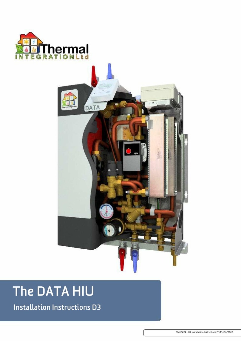
THERMAL INTEGRATION DATA Extra HIU User manual

The DATA Extra HIU, Installation Instructions DE2 12/08/2021
The DATA Extra HIU
Installation Instructions DE2

The DATA Extra HIU, Installation Instructions DE2, 12th August 2021
The DATA Extra HIU, Installation Instructions DE2
Wiki Binder, 12th August 2021
Explanation of symbols and abbreviations .................................... 3
Introduction .......................................................... 4
Key Components ....................................................... 5
Available Options ...................................................... 6
Dimensions .......................................................... 7
Technical Data ........................................................ 8
Description .......................................................... 9
Operation ........................................................... 10
Adjusting Settings ..................................................... 11
Factory Settings ...................................................... 12
General Plumbing Requiremenrts ......................................... 13
General Wiring Requirements ............................................ 14
HIU Schematic ....................................................... 15
Installation Schematic .................................................. 16
Wiring Schematic ..................................................... 17
Important Installation Requirements ....................................... 18
Service and Inspection .................................................. 20
DHW Performance .................................................... 21
Central Heating Temperature Curves ....................................... 25
Installation Set-up .................................................... 27
Adjusting Temperatures and Settings ....................................... 35
Troubleshooting for End users ............................................ 39
Troubleshooting (for Technicians) ......................................... 40
Guarantees and After Sales Backup for HIUs .................................. 41
Page 2

The DATA Extra HIU, Installation Instructions DE2, 12th August 2021
Introduction
The DATA Extra HIU enables us to take the functions of our flagship twin plate DATA HIU and increase the heating output to cater for
commercial or industrial applications. The basis of this HIU is our SLIM hot water only HIU and then we add a heating plate heat
exchanger and Danfoss pressure independent control valve with a Novocon Actuator for the heating side of the HIU. Both the heating
and hot water controls are linked to our Node-iHIU system and can be accessed remotely for monitoring and adjustment.
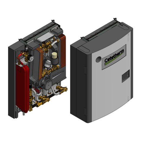
The fully insulated HIU is enclosed within a white steel enclosure designed to keep the overall footprint of the HIU to an absolute
minimum. If required, the expansion vessel, safety relief valve, filling loop and pump are mounted external to the casing, allowing the
HIU to be fitted out of the way, with key components mounted in a more accessible location.
The heating installation must be equipped with a correctly sized expansion vessel and safety relief valve fitted between the HIU
and any isolation valve on the heating circuit. It is also advisable to fit a filling loop and pressure gauge to the heating system, in
a location convenient for the end user to access and top-up the central heating system. Refer to the chapter on "Installation
Requirements" for more information. Contact Thermal Integration for more information on parts availability and advice on
system safety.
Page 4

The DATA Extra HIU, Installation Instructions DE2, 12th August 2021
Key Components
Parts List
Item No. Description Pt. No.
1 SLIM HIU 70TILSLIM
2 Node-iHIU Control 70DATA-Extra-Control
3 CH Plate Heat Exchanger 7028768
4 CH Control Valve 70610
5 CH Control Valve Actuator 70NOVO003Z8500
6 Heat Meter 70HM403-2.5-G1B-130
7 Primary Flow Temperature Sensor 70HSF51862
8 Primary Return Temperature Sensor 70HSF51862
9 CH Flow Temperature Sensor 70HSF51862
10 Manual Air Vent N/A
11 Heat Meter Flow Temperature Sensor N/A
12 DHW Plate Heat Exchanger 7066561
13 DHW Stepper Control Valve 70HSF51495
14 Universal HIU Controller 70HSFCONTROL
15 DHW Flow Sensor 70HSF50274
16 DHW Temperature Sensor 70HSF52727
17 Primary Return Temperature Sensor 70HSF52726
18 Primary Flow Temperature Sensor 70HSF52727
Not Shown Optional Differential Pressure Sensor 70200216-2
Page 5

The DATA Extra HIU, Installation Instructions DE2, 12th August 2021
Available Options
The unit has several options available depending on requirements. The basic unit can be equipped with any combination of the
following:
Landlord security valve, allows the landlord to remotely isolate the unit from the district heating network if required.
Differential pressure control valve, to balance differential pressures between the primary flow and return. Only required where the
differential pressure exceeds 250kPa. (Max 450kPa)
Flushing Bypass for connecting to the primary flow and return pipework (External to the unit)
External DHW recirculation unit, to provide constant circulation of DHW throughout the property in order to allow quicker response
times at the tap where extended pipe runs are unavoidable.
Heat Meter. It is possible to fit most brands of heat meter into the HIU, contact Thermal Integration for further information.
Page 6

The DATA Extra HIU, Installation Instructions DE2, 12th August 2021
Technical Data
Primary
Nominal primary supply temperature 85°C
Maximum primary supply temperature 90°C *
Minimum primary supply temperature 55°C **
Maximum primary differential pressure 250kPa
Minimum primary differential pressure 50kPa ***
Pressure class DH circuit PN16
Domestic Hot Water
Nominal DHW supply temperature 55°C
DHW Set Range 45°C to 60°C
Domestic Hot water heat exchanger (DHW) E8LAS40
Keep Warm Modes Economy / Comfort
Keep Warm Temperature 25°C to 60°C
Keep Warm Duration 0 to 120 mins or Always On
Max Return Temperature during Keep Warm Mode DHW Setpoint -2°C
DHW Max pressure 6 Bar
Pressure class DHW circuit PN10
DWH Priority Multi-Stage ****
Central Heating
Maximum flow temperature Primary T -5°C
Return Temp Limit Range 35°C to 55°C
CH Limit Range 30°C to 80°C
Central heating heat exchanger (CH) B25TH30
Pressure class CH circuit (3 bar safety valve) PN16
CH working pressure N/A (By Installer)
Nominal pump pressure 20 kPa (Adj. 0-70)
Maximum recommend flow rate 750 l/hr
General
Primary connections DN32 Female
Mains & DHW connections ¾” Female
Central heating connections ¾” Female
Casing width 653mm
Casing height 900mm
Casing depth 225mm
Casing Material Steel
HIU Insulation Material EPP Expanded Polypropylene
Pipework Insulation Material Grey Polyethylene Foam
Maximum Heat Losses <50W (1.2 kWh/day)
Weight (basic version) 35kg Approx
Electrical supply info 230V 50Hz - 0.64A
Power consumption per year circa 45kWh
Fuse ratings 3 Amp
Sensors NTC 10kohm @ 25°C
.* Maximum primary supply temperature 100°C for momentary spikes.
.** Minimum required DH supply temperature is DHW setpoint + 5°C with a minimum of 55°C.
.*** Depends on requested DHW output and available DH supply temperature.
.**** See Multi-Stage DHW Priority example below.
Page 8

The DATA Extra HIU, Installation Instructions DE2, 12th August 2021
Description
The HIU is for use in properties connected to a district heating system using a centralised boiler and is suitable for both central heating
and domestic hot water. Each hydraulic circuit to which the HIU is connected, must meet minimum water quality standards as stated in
document "Requirements on water quality" available on our Wiki Site at www.heatweb.co.uk/w.
Please keep the following conditions in mind during installation:
The unit must be installed in a frost free area.
The unit must not be exposed to direct sunlight.
Ambient temperature should be between +5°C and +40°C.
Humidity should be between 10% and 85%.
The unit must be connected to a fused double pole isolator.
The unit uses 230 VAC. Use caution when handling. Contact may lead to shock, burns or electrocution.
Components in the unit and connected to the unit can reach high temperatures. Contact may lead to burns.
DHW Status Indicator LED
Green blinking slowly (about 1x per second): HIU is at rest; there is no heat demand and all control valves are closed.
Blue blinking: HIU is in Hot water mode; there is a water draw-off and the control valve is open.
Red blinking: Error
White continuous (only for engineers): HIU is in service mode
No LED: HIU is switched off
Page 9

The DATA Extra HIU, Installation Instructions DE2, 12th August 2021
Operation
The HIU is equipped with two heat exchangers, the left hand heat exchanger transfers the heat from the district heating system to the
DHW circuit and the right hand heat exchanger transfers the heat from the district heating system to the CH circuit. These heat
exchangers ensure hydraulic separation between the property and the district heating network. The hot water in the district heating
network does not come into contact with the hot water or heating circuit of the property. Heat is transferred from the district heating
network via the heat exchangers to the domestic hot water system and central heating system.
Central heating
The temperature of the property's heating system is controlled automatically by the HIU, with the temperature set-point being
adjustable via the Modbus interface. When heating demand finishes, the heating pump will be switched off after a defined pump over-
run time (default: 15 minutes).
Domestic Hot Water
The electronics within the unit, together with domestic hot water control valve, temperature sensors and flow sensor, regulate the
temperature of the hot water to it's set point (As Standard 55°C). The HIU has a very low switching point, recognising DHW flow rates as
low as 1 l/min.
Each HIU has two domestic hot water keep hot modes, 'Eco' or 'Comfort' mode. These can only be selected during commissioning or by a
trained engineer.
'Eco' mode can be specified to run for 0 minutes (which turns the feature off all together), 15, 30, 60 or 120 minutes after the last hot
water draw off. In 'Eco' mode the heat exchanger is kept to a specified temperature (between 25 and 60°C) for the selected period of
time and after this period of inactivity has elapsed the control valve closes completely and the temperature in the domestic hot water
circuit is allowed to drop through natural dissipation to minimize energy consumption. If a hot water draw off is made any time
throughout the Eco mode function the unit will deliver hot water as usual and the 'Eco' mode function will begin counting down for the
selected time once again.In 'Comfort' mode the heat exchanger is continuously supplied with a trickle of primary water for quicker hot
water delivery, however energy consumption will be slightly higher than if the unit was set in 'Eco' mode.
To prevent legionella from growing the heat exchanger is heated to 60°C for at least 60 minutes every 24 hours. (it is not possible to
specify the time at which this occurs)
The hot water temperature is regulated to temperatures as high as 60°C. If there is a power outage during DHW draw off, units
not fitted with a landlord security valve will stop regulating the hot water temperature. This may lead to a hot water temperature
that is higher or lower than the setpoint. Hot water can cause burns.
Page 10

The DATA Extra HIU, Installation Instructions DE2, 12th August 2021
Adjusting Settings
The DATA Extra requires connection to either a PC running the commissioning software, or by the use of an iHIU Controller, in order to
adjust settings.
End users cannot adjust settings, unless an iHIU Controller is used.
PC Software
The software is made freely available, along with training, to registered commissioning engineers. Please contact Thermal Integration
for further information.
The software allows one to adjust the following settings:
Setting Options Default
Domestic Hot Water Temperature 45°C to 60°C 50°C
Primary Differential Pressure Auto or Manual from 0.3 to 2.0 bar Auto
Warmup Boost Flow Rate 8 to 20 l/min 20 l/min
Return Temperature Limit Disabled or Enabled from 35°C to 65°C Enabled 50°C
Maximum Central Heating Temperature 30°C to 80°C 80°C
Central Heating Pump Timeout 0 to 30 minutes 15 minutes
iHIU Controller
The iHIU Controller is a miniature Linux web server that can be supplied separately to provide more advanced control and monitoring of
the Data HIU. The controller is typically mounted within the casing of the HIU, with an option for a display on the front of the HIU.
The controller provides a WiFi zone, and can log onto existing networks through either WiFi or Ethernet to gain access to the internet.
The HIU can then be controlled directly from other devices on the local network, such as smartphones. Once connected to the internet
the system can provide remote control and monitoring services, as well as many other features, some of which are listed below:
Browser based cross platform interface that adjusts to screen size
Allows setting of all the parameters available to the PC software, except via a browser
Control over central heating as well as other settings via Google Calendar
Remote commissioning
Remote fault alarms and message forwarding via email or SMS
Voice control over services via Android app
Connection to Energy Saving Trust's Embed Database for free and secure online storage of all system data
Page 11

The DATA Extra HIU, Installation Instructions DE2, 12th August 2021
Factory Settings
DHW Settings
The DHW settings are factory set, and these can only be changed by connecting a laptop directly to the SLIM HIU communication cable
and using the HIU Monitor Application Software available from Thermal Integration. If the DATA Extra HIU is connected to a BMS, it is
possible to alter the settings through the BMS ModBus interface.
The factory settings are as follows:-
Setting Limits Set Value
Temperature - DHW 45 - 60C 55C
Pressure Manual / Auto Auto
Ecoheat Time (keep warm) Off,15, 30, 60, 120, Always Off
Ecoheat Temperature 25 - 60C N/A
Legionella Prevention Cycle On / Off Off
District Heating Warmup Boost 8 - 20 l/min 20 l/min
Central Heating Settings
Setting Limits Set Value
Temperature - CH 20 - 80C 60C
Pump Over-run any 60 secs
Return Temperature Monitoring On / Off Off
Return Temperature Limit 30 - 55C 55C*
CH Control Valve Pre-set 10 - 100% 100%
If the Return Temperature Monitoring function is set to 'Off' the Return Temperature Limit is irrelevant.
Multi-Stage DHW Priority
If DHW priority is not suitable for the installation location (for instance in a restaurant or hair dressers, where hot water draw-offs may
be frequent and therefore hold off the heating output), the primary flow rate available for the HIU to operate simultaneously in both
DHW and CH modes, does not need to be the sum of the two circuits. This is due to the Multi-Stage DHW Priority feature built into the
HIU software.
This feature allows peek or multi-staged flow limits to be set, which enables the DHW priority to be off-set against a proportion of the
heating flow. Although it is possible to set specific flow rates and reductions, An example of the basic principle is explained below:-
DHW primary flow rate =
0 to 25%, no effect on the heating output
25 to 50%, heating output reduced by 25%
50 to 75%, heating output reduced by 50%
75 100%, heating off completely.
Page 12

The DATA Extra HIU, Installation Instructions DE2, 12th August 2021
General Plumbing Requiremenrts
NEW COMPLETE SYSTEM INSTALLATIONS: When carrying out a completely new heating system installation in a new build
property or a first time installation in an existing property, then the heating system must conform to current building regulations Part
L1a. All new domestic heating systems must have a minimum of two heating zones. Each of these zones should be controlled by a
thermostat and zone valve. Alternatively individual electronically controlled Thermostatic Radiator Valves may be fitted. If domestic
hot water is provided by a storage system then the storage system or cylinder will require separate time and temperature control.
All radiators must have TRV's fitted in all rooms except bathrooms and any rooms where a thermostat is located. The exception to this
are single storey, open plan dwellings where the living area is more than 70% of the total usable floor area. Then this type of dwelling
can be controlled as one zone.
EXISTING INSTALLATIONS: When carrying out boiler replacements on an existing system, the regulations do not require separate
zoning of the upstairs and downstairs and compliance with the regulations can be achieved by a single room thermostat or
programmable room thermostat. It is however recommended that TRV's are fitted to all rooms except the bathrooms and the room
where a thermostat is located.
The appliance must be installed in accordance with, and comply to, the current: IEE Regulations, Building Regulations, Building
Standards (Scotland) (Consolidation), Building Regulations (Northern Ireland), local water by-laws, Health & Safety Document
635 (The Electricity at Work Regulations 1989) and any other local requirements.
BRITISH & IRISH STANDARDS Where no specific instruction is given, reference should be made to the relevant British and/or Irish
Standard codes of Practice.
BS7074:1 Code of practice for domestic and hot water supply
EN12828 Central heating for domestic premises
BS7593 Treatment of water in domestic hot water central heating systems
ECTI National rules for electrical installations
POTABLE WATER: All seals, joints and compounds (including flux and solder) and components used as part of the secondary domestic
water system must be approved by WRAS.
FITTING AND MODIFICATIONS: Fitting the appliance and any controls to the appliance may only be carried out by a competent
engineer. Any misuse or unauthorised modifications to the appliance or associated components and systems could invalidate the
guarantee and may lead to serious injury or even death. The manufacturer accepts no liability arising from any such actions, excluding
statutory rights.
SERVICING: The end user should be advised to have the system serviced annually by a competent engineer. Contact Thermal
Integration Ltd for a list of approved engineers. Approved spares must be used to help maintain the economy, safety and reliability of
the appliance. The service engineer must complete the Service Record after each service.
Page 13

The DATA Extra HIU, Installation Instructions DE2, 12th August 2021
General Wiring Requirements
These instructions apply in the UK and Ireland only and must be followed except for any statutory obligations. Component specific
electrical information may also be supplied in support of these instructions, however if there is any doubt please contact Thermal
Integration Ltd. (Tel: 0345 2411441)
FAILURE TO INSTALL APPLIANCES CORRECTLY COULD LEAD TO PROSECUTION.
The appliance must be installed in accordance with, and comply to, the current: IEE Regulations, Building Regulations, Building
Standards (Scotland) (Consolidation), Building Regulations (Northern Ireland), local water by-laws, Health & Safety Document
635 (The Electricity at Work Regulations 1989) and any other local requirements.
BRITISH & IRISH STANDARDS: Where no specific instruction is given, reference should be made to the relevant British and/or Irish
Standard codes of Practice.
BS7074:1 Code of practice for domestic and hot water supply
EN12828 Central heating for domestic premises
BS7593 Treatment of water in domestic hot water central heating systems
ECTI National rules for electrical installations
CAUTION: ISOLATE THE MAINS SUPPLIES BEFORE STARTING ANY WORK AND OBSERVE ALL RELEVANT SAFETY
PRECAUTIONS.
Danger of short circuit: When connecting the cables ensure that no cable pieces fall inside the control panel.
The Mains supply to the appliance must be through a fused double pole isolator situated next to the appliance. The isolator must have a
contact separation of 3mm minimum in all poles and should isolate the appliance and all associated controls.
Unless otherwise stated, all Heat Interface Units should be connected to a mains 230V 50Hz Supply fused at 3 Amps.
All electrical connections with the Heat Interface Unit control panel are clearly marked as follows:
L = Live 230V
N = Neutral
E = Earth
Any additional mains cable should comply fully with the current I.E.E. wiring regulations. It must have a minimum section of 0.75mm2
and be capable of withstanding a minimum of 85C.
Page 14

The DATA Extra HIU, Installation Instructions DE2, 12th August 2021
Important Installation Requirements
Components in the HIU, pipes and radiators may reach high temperatures. The HIU is designed for heat distribution networks
with water temperatures up to 95°C. The pipes and parts in the HIU as well as pipes and radiators in the heating system can also
reach this temperature. Contact can lead to burns.
Central Heating
When installing the HIU, the following conditions must be observed (see the following diagrams):
1. The heating installation must be equipped with a correctly sized expansion vessel and safety relief valve fitted between the HIU and
any isolation valve on the heating circuit.
2. It is advisable to fit a filling loop and pressure gauge to the heating system, in a location convenient for the end user to access and top
up the central heating system.
3. The heating system must be equipped with a WRAS approved over pressure safety relief valve (rated to 3 bar), fitted between the HIU
and any isolation valve on the heating circuit.
4. A heating control valve must not be installed in the heating circuit. The room thermostat should, if used, be connected to the room
thermostat cable of the HIU.
5. Before the unit is commissioned, the central heating circuit must be fitted with an automatic bypass valve to maintain a minimal flow
rate and regulate pressure across the system. The valve must be installed between the central heating flow and return, noting the
direction of flow. The automatic bypass must be fitted before any isolation valve on the heating circuit.
NOTE For optimal energy efficiency and comfort, it is of the utmost importance to hydraulically balance the CH system correctly. For
the same purpose it is advisable to design the CH system in such a way that the CH return temperatures are as low as possible.
* Artificially softened water must not be used to fill the central heating system
.
.
DHW Recirculation Unit
Page 18

The DATA Extra HIU, Installation Instructions DE2, 12th August 2021
The DHW recirculation unit is an available option for fitting external to the HIU. The recirculation system must not contain any
isolation valves. Applying valves to the system can cause the pump to overheat due to insufficient flow.
Keep the following conditions in mind during installation:
Maximum pressure supplied by the domestic water circuit is 10 bar.
All seals, joints and compounds (including flux and solder) and components used as part of the secondary domestic water system
must be WRAS approved.
Page 19

The DATA Extra HIU, Installation Instructions DE2, 12th August 2021
Service and Inspection
Components in the HIU, pipes and radiators may reach high temperatures. The HIU is designed for heat distribution networks
with water temperatures up to 95°C. The pipes and parts in the HIU as well as pipes and radiators in the heating system can also
reach this temperature. Contact can lead to burns.
To ensure the unit functions properly, it is advised to periodically inspect the installation.
Maintenance and repairs should be carried out by recognised personnel only.
Remove the power from the unit when performing maintenance and/or repairs.
Connect the flow and return valve from the district heating network.
Connect the flow and return valve on the unit.
Check the unit for leaks.
Check the primary and central heating strainer for debris and clean if necessary.
Check valves for debris and clean if necessary.
Check the unit operates satisfactorily in domestic hot water and central heating modes.
The casing can be cleaned with a damp cloth. Do not use detergents of any kind.
The unit uses electrical components (230Vac, 24Vdc & 5Vdc). These components must stay dry at all times. Contact with these
energised components can result in an electrical shock, burn, or electrocution.
Prolonged Absence or Holiday
Do not switch the unit off during periods of prolonged absence or holiday. To prevent frost damage within the unit or the distribution
network, the radiator and shutoff valves MUST remain open. Radiators can be switched to the frost protection position (slightly
opened) and/or the room thermostat lowered to a MINIMUM of 10°C. It is recommended to flush all water tapping points and showers
for at least 2 minutes after a long period of absence.
Page 20
Table of contents
Other THERMAL INTEGRATION Heating System manuals


