THERMAL INTEGRATION DATA User manual

The DATA HIU, Installation Instructions D3 13/06/2017
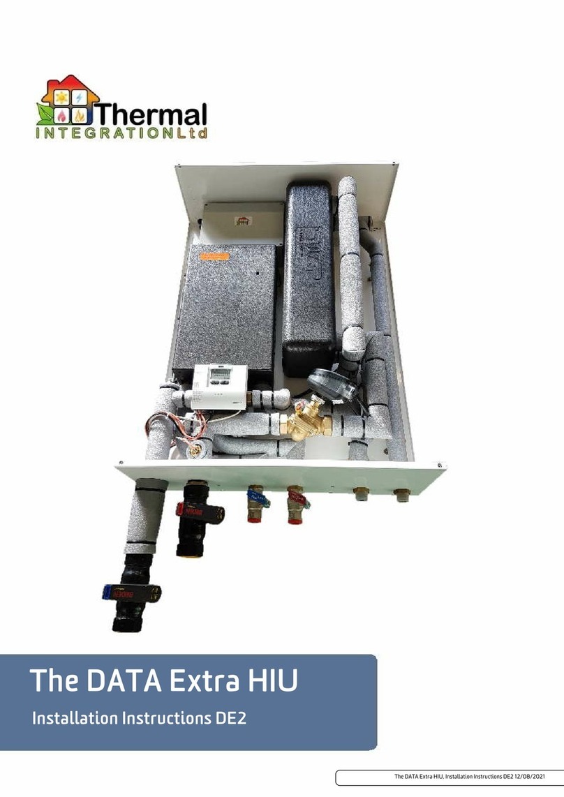
The DATA HIU
Installation Instructions D3

The DATA HIU, Installation Instructions D3, 13th June 2017
The DATA HIU, Installation Instructions D3
Wiki Binder, 13th June 2017
About Thermal Integration ................................................ 3
Explanation of symbols and abbreviations .................................... 4
Overview of Components and Connections ..................................... 5
Options ............................................................. 6
Dimensions .......................................................... 7
Technical Data ........................................................ 8
Application ........................................................... 9
General Plumbing Requirements .......................................... 11
General Wiring Requirements ............................................ 12
Schematic Layout ..................................................... 13
Wiring Diagram ...................................................... 14
Installation Requirements ............................................... 16
Installation Setup ..................................................... 18
Stage 1 - Pre-Fix Bracket Positioning ....................................... 19
Stage 2 - HIU Preparation ............................................... 20
Stage 3a - Fixing HIU ................................................... 21
Stage 3b - Pipework Connections .......................................... 22
Stage 4 - Fitting a Heat Meter ............................................ 23
Stage 5 - Filling the Heating System ........................................ 24
Stage 6 - Bleeding the Unit .............................................. 25
Stage 7 - Programmer and Room Thermostat Connection ......................... 26
Stage 8 - Connect Power ................................................ 27
Adjusting Settings ..................................................... 29
Securing the Casing .................................................... 30
Service & Inspection ............................................... 31
Draining the Unit ..................................................... 32
Pump Settings (Wilo) .................................................. 33
Pump Settings (Grundfos) ............................................... 34
DHW Recirculation Pump (Optional) ........................................ 36
Differential Pressure Valve (Optional) ...................................... 37
Troubleshooting (End Users) ............................................. 38
Troubleshooting For Technicians .......................................... 39
Heat Meter ......................................................... 40
Dirt and Air Separation ................................................. 41
Guarantees and After Sales .............................................. 42
DATA EC Declaration ................................................... 44
Page 2

The DATA HIU, Installation Instructions D3, 13th June 2017
About Thermal Integration
About Us
We design and manufacture pre-fabricated Hot Water and Central Heating Cylinders, Thermal Stores, Buffer Tanks and Heat Interface
Units to suit almost any domestic or commercial application. Our range of products is the end result of over 20 years of continuous
development and improvement in heating technology. We hold to the philosophy that all customers deserve our best level of service for
the life of the product, as well as complete honesty throughout the product selection process. We hold a significant number of patents
in the fields of water storage, heat exchange, and the networking of communal heating systems, and continue to push the boundaries.
As well as the most comprehensive range of hot water systems in the UK, our headquarters in Sudbury also offers the UKs largest
renewables training centre, including the first HETAS training and test centre, with working wood, pellet and log biomass rigs, as well
as solar. There is also an extensive district heating demonstration and test facility attached to the factory, with the factory building
services running from a twin pellet biomass boiler installation, buffer storage, and HIUs to provide services. The entire facility is
controlled using our in-house IHIU Control Systems that allow any of our products to be network connected, with online monitoring and
dashboard facilities.
For a complete history of the company please read History of Thermal Integration Limited on Heatweb Wiki.
Product Range
Heat Interface Units
Standard Cylinders
Shortened Cylinders
Buffer Cylinders
Combination Cylinders
Mains Pressure Thermal Stores
Mains Hot Water Conversion Kits
Prefabricated Systems
Plate Heat Exchangers
Boiler Conversion Kits
Control Systems
Knowledge Base
To make the dissemination of technical material as simple as possible, we publish all our documentation through an online document
storage system, the Heatweb Wiki. Links to further information may be found throughout documents.
Useful Contacts
Commercial Sales and Operations: 0845 2411441
Specflue Sales: 0333 9997974
Web Sites
http://www.heatweb.co.uk Company Website
http://www.systemdesigner.co.uk System Designer
http://wiki.heatweb.com/wiki Heatweb Wiki
http://www.heatweb.info Monitoring software and online APIs
Page 3

The DATA HIU, Installation Instructions D3, 13th June 2017
Overview of Components and Connections
1 Primary circuit strainer
2 Back casing
3 Primary flow temperature sensor
4 Heat meter sensor pocket
5 Automatic air vent (central heating)
6 Electronics 230 V
7 Electronics 24 V
8 Heat exchanger (central heating)
9 Domestic Hot Water Temperature sensor
10 Heat exchanger (DHW)
11 Central heating pump
12 Domestic Hot Water control valve
13 Domestic Hot Water primary return temperature sensor
14 Central heating strainer
15 Filling point
16 Flow sensor
17 Pressure/temperature gauge
18 Temperature/pressure sensor central heating supply
19 Pressure relief valve (3 Bar)
20 Temperature sensor central heating primary return
21 Heat meter spool piece
22 Central heating control valve
23 Expansion vessel
24 Expansion vessel bleed valve
Page 5

The DATA HIU, Installation Instructions D3, 13th June 2017
Options
The unit has several options available depending on requirements. The basic unit can be equipped with any combination of
thefollowing:
Option A1: Spool piece, used when neither option A2 or A3 are required.
Option A2: Landlord security valve, allows the landlord to remotely isolate the unit from the district heating network if required.
Option A3: Differential pressure control valve, to balance differential pressures between the primary flow and return. Only required
where the differential pressure exceeds 250kPa. (Max 450kPa)
Option B: Water hammer arrestor, reduces water hammer within the DHW circuit.
Option C: DHW recirculation unit, to provide constant circulation of DHW throughout the property in order to allow quicker
response times at the tap where extended pipe runs are unavoidable. Note: The unit must be set to 'Comfort' Mode by the installer,
when this option is fitted.
Option D: Decorative casing, attractive white painted steel casing.
Option E1: Standard Output Domestic Hot Water, up to 65kW (at 10-60C)
Option E2: Plus output Domestic Hot Water, up to 80kW (at 10-60C)
Option F: Flushing Bypass for connecting to the primary flow and return pipework (External to the unit)
Page 6

The DATA HIU, Installation Instructions D3, 13th June 2017
Technical Data
Description Data
Nominal primary supply temperature 80C
Maximum primary supply temperature 85C
Minimum primary supply temperature 55C *
Nominal DHW supply temperature 55C
DHW Set Range 45C to 60C
Return Temp Limit Range 35C to 65C
CH Limit Range 30C to 80C
Primary connections Female / 18mm
Mains & DHW connections Female / 18mm
Central heating connections Female / 18mm
Pressure relief 15mm
Domestic Hot water heat exchanger (DHW) E8LAS40
Central heating heat exchanger (CH) E8LAS40
Maximal primary differential pressure (without dP regulator) 250kPa
Maximal primary differential pressure (with dP regulator) 450kPa
Minimal primary differential pressure 50kPa **
Pressure class DH circuit PN16
Pressure class CH circuit (3 bar safety valve) PN10
Pressure class DHW circuit PN10
CH Maximum working pressure 2.5 Bar
Casing width 490mm
Casing height 640mm
Casing depth 275mm
Casing Material EPP Expanded Polypropylene
Maximum Heat Losses 50W (1.2 kWh/day)
Typical Heat Losses (DHW Only, Keep Warm) 25W
Weight (basic version) 24kg ***
Electrical supply info 230V 50Hz
Fuse ratings 3 Amp
Sensor DHW NTC 10kohm @ 25C
Keep Warm Modes Economy / Comfort
Max Return Temperature during Keep Warm Mode DHW Setpoint - 2C
.* Minimum required DH supply temperature is DHW setpoint + 5C with a minimum of 55C.
.** Depends on requested DHW output and available DH supply temperature.
.*** Unit weight may vary depending on the optional components built into the unit
Page 8

The DATA HIU, Installation Instructions D3, 13th June 2017
Application
The Data twin plate HIU is used to provide hot water and central heating in properties connected to a district heating systemusing a
centralised boiler. Please keep the following conditions in mind during installation:
The unit must be installed in a frost free area.
The unit must not be exposed to direct sunlight.
Ambient temperature should be between +5C and +40C.
Humidity should be between 10% and 85%.
The unit must be connected to a fused double pole isolator.
The unit uses 230 VAC. Use caution when handling. Contact may lead to shock, burns or electrocution.
Temperatures of components in the unit and connected to the unit can reach high temperatures. Contact may lead to burns.
Status indicator LED
Green blinking (slow): Normal condition
Green blinking (fast): Heating demand
Blue blinking: Domestic Hot Water Mode / Tap draw-off
Red blinking: Error
White continuous: Service mode (installer only)
No LED: HIU is switched off
Page 9

The DATA HIU, Installation Instructions D3, 13th June 2017
Operation
Central Heating
The heat exchanger physically separates the district heating network and the central heating circuit. The application minimises the
riskof contamination of district heating water as well as the risk and consequences of leakage in the central heatingsystem.
Components, pipes and radiators in, and connected to the unit may be hot. The DATA heat interface unit is designed for use with
centralised heating systems up to 85C. The pipes and components in the unit and the pipes and radiators in the central heating
installation can reach temperatures of 80C and contact may lead to burns.
Domestic Hot Water
The unit is equipped with single walled plate heat exchangers. The front heat exchanger transfers the heat from the district
heatingsystem to the DHW. The electronics within the unit, together with domestic hot water control valve, temperature sensors and
flowsensor, regulate the temperature of the hot water to it's set point (As Standard 55C).
Each HIU has two domestic hot water keep hot modes, Eco or Comfort mode. These can only be selected during commissioning or by a
trained engineer.
The default setting is Eco mode, and this can be specified to run for 0 minutes (which turns the feature off all together), 15, 30, 60 or
120 minutes after the last hot water draw off. In Eco mode the heat exchanger is kept to a specified temperature (between 25 and 60
Deg C) for the selected period of time and after this period of inactivity has elapsed the stepper motor closes completely and the
temperature in the domestic hot water circuit is allowed to drop through natural dissipation to minimize energy consumption. If a hot
water draw off is made any time throughout the Eco mode function the unit will deliver hot water as usual and the Eco mode function
will begin counting down for the selected time once again.In Comfort mode the heat exchanger is continuously supplied with a trickle of
primary water for quicker hot water delivery, however energy consumption will be slightly higher than if the unit was set in Eco mode.
To prevent legionella from growing the heat exchanger is heated to 57C for at least 30 minutes every 24 hours. (it is not possible to
specify the time at which this occurs)
The hot water temperature is regulated to approximately 55C. If there is a power outage during DHW draw off, units not fitted
with a landlord security valve will stop regulating the hot water temperature. This may lead to a hot water temperature that is
higher or lower than 55C. Hot water can cause burns.
Priority Switching
The unit is fitted with domestic hot water priority switching. When hot water is drawn off, the central heating control valve will
close,diverting all primary flow to heat the domestic hot water circuit. Primary flow to the central heating is cut off during hot water
delivery.Primary flow to the central heating is resumed after the hot water draw off has finished.
Page 10

The DATA HIU, Installation Instructions D3, 13th June 2017
General Plumbing Requirements
NEW COMPLETE SYSTEM INSTALLATIONS When carrying out a completely new heating system installation in a new build property
or a first time installation in an existing property, then the heating system must conform to current building regulations Part L1a. All
new domestic heating systems must have a minimum of two heating zones. Each of these zones should be controlled by a thermostat
and zone valve. Alternatively individual electronically controlled Thermostatic Radiator Valves may be fitted. If domestic hot water is
provided by a storage system then the storage system or cylinder will require separate time and temperature control.
All radiators must have TRV's fitted in all rooms except bathrooms and any rooms where a thermostat is located. The exception to this
are single storey, open plan dwellings where the living area is more than 70% of the total usable floor area. Then this type of dwelling
can be controlled as one zone.
EXISTING INSTALLATIONS: When carrying out boiler replacements on an existing system, the regulations do not require separate
zoning of the upstairs and downstairs and compliance with the regulations can be achieved by a single room thermostat or
programmable room thermostat. It is however recommended that TRV's are fitted to all rooms except the bathrooms and the room
where a thermostat is located.
The appliance must be installed in accordance with, and comply to, the current: IEE Regulations, Building Regulations, Building
Standards (Scotland) (Consolidation), Building Regulations (Northern Ireland), local water by-laws, Health & Safety Document
635 (The Electricity at Work Regulations 1989) and any other local requirements.
BRITISH & IRISH STANDARDS Where no specific instruction is given, reference should be made to the relevant British and/or Irish
Standard codes of Practice.
BS7074:1 Code of practice for domestic and hot water supply
EN12828 Central heating for domestic premises
BS7593 Treatment of water in domestic hot water central heating systems
ECTI National rules for electrical installations
Potable water: All seals, joints and compounds (including flux and solder) and components used as part of the secondary domestic
water system must be approved by WRAS.
CH Water: Artificially softened water must not be used to fill the central heating system.
FITTING AND MODIFICATIONS: Fitting the appliance and any controls to the appliance may only be carried out by a competent
engineer. Any misuse or unauthorised modifications to the appliance or associated components and systems could invalidate the
guarantee and may lead to serious injury or even death. The manufacturer accepts no liability arising from any such actions, excluding
statutory rights.
SERVICING: The end user should be advised to have the system serviced annually by a competent engineer. Contact Thermal
Integration Ltd for a list of approved engineers. Approved spares must be used to help maintain the economy, safety and reliability of
the appliance. The service engineer must complete the Service Record after each service.
Page 11

The DATA HIU, Installation Instructions D3, 13th June 2017
General Wiring Requirements
These instructions apply in the UK and Ireland only and must be followed except for any statutory obligations. Component specific
electrical information may also be supplied in support of these instructions, however if there is any doubt please contact Thermal
Integration Ltd. (Tel: 0845 2411441)
FAILURE TO INSTALL APPLIANCES CORRECTLY COULD LEAD TO PROSECUTION.
The appliance must be installed in accordance with, and comply to, the current: IEE Regulations, Building Regulations, Building
Standards (Scotland) (Consolidation), Building Regulations (Northern Ireland), local water by-laws, Health & Safety Document
635 (The Electricity at Work Regulations 1989) and any other local requirements.
BRITISH & IRISH STANDARDS: Where no specific instruction is given, reference should be made to the relevant British and/or Irish
Standard codes of Practice.
BS7074:1 Code of practice for domestic and hot water supply
EN12828 Central heating for domestic premises
BS7593 Treatment of water in domestic hot water central heating systems
ECTI National rules for electrical installations
Potable water: All seals, joints and compounds (including flux and solder) and components used as part of the secondary domestic
water system must be approved by WRAS.
CH Water: Artificially softened water must not be used to fill the central heating system.
CAUTION: ISOLATE THE MAINS SUPPLIES BEFORE STARTING ANY WORK AND OBSERVE ALL RELEVANT SAFETY
PRECAUTIONS.
Danger of short circuit: When connecting the cables ensure that no cable pieces fall inside the control panel.
The Mains supply to the appliance must be through a fused double pole isolator situated next to the appliance. The isolator must have a
contact separation of 3mm minimum in all poles and should isolate the appliance and all associated controls.
Unless otherwise stated, all Heat Interface Units should be connected to a mains 230V 50Hz Supply fused at 3 Amps.
All electrical connections with the Heat Interface Unit control panel are clearly marked as follows:
L = Live 230V
N = Neutral
E = Earth
Any additional mains cable should comply fully with the current I.E.E. wiring regulations. It must have a minimum section of 0.75mm2
and be capable of withstanding a minimum of 85C.
Page 12

The DATA HIU, Installation Instructions D3, 13th June 2017
Installation Requirements
Components, pipes and radiators in, and connected to the unit may be hot. The DATA heat interface unit is designed for use with
centralised heating systems up to 85C. The pipes and components in the unit and the pipes and radiators in the central heating
installation can reach temperatures of 80C and contact may lead to burns.
To ensure the life expectancy of the unit, the system must meet certain requirements. Keep following conditions in mind during
installation:
Maximum pressure supplied by the district heating network is 10 bar.
Maximum differential pressure supplied by the district heating network is 250 kPa. (450 kPa when differential pressure valve is
fitted)
Maximum supplied temperature by the distict heating network is 90C.
Minimal supply temperature is setpoint DHW + 5C.
Central heating
Before the unit is commissioned, the central heating circuit must be fitted with an automatic bypass valve to maintain a minimal
flowrate and regulate pressure across the system. The valve must be installed between the central heating supply and return, noting
thedirection of flow.
ABV = Automatic Bypass Valve
NOTE For optimal energy efficiency and comfort, it is of the utmost importance to hydraulically balance the CH system correctly. For
the same purpose it is advisable to design the CH system in such a way that the CH return temperatures are as low as possible.
* Artificially softened water must not be used to fill the central heating system
Page 16

The DATA HIU, Installation Instructions D3, 13th June 2017
DHW Recirculation Unit
The DHW recirculation unit is an available option within the unit. The circulation system connected to the unit must not contain
anyclosable valves. Applying valves to the system can cause the pump to overheat due to insufficient flow.
Keep following condition in mind during installation:
Maximum pressure supplied by the domestic water circuit is 10 bar.
All seals, joints and compounds (including flux and solder) and components used as part of the secondary domestic water system
must be WRAS approved.
Page 17

The DATA HIU, Installation Instructions D3, 13th June 2017
Stage 1 - Pre-Fix Bracket Positioning
The following dimensions for for the extended pre-fix kit.If a flushing by-pass is to be fitted, please refer to the relevant page.
1.Mark out the wall with the fixing points using the dimensions shown below.
2.Drill holes using a suitable drill bit to suit wall plugs provided in accessory pack.
3.Using a level, fit first fix brackets to wall.
4.Continue with external pipework as required. With isolating valves closed the systems can be filled for testing.
Mounting to a plywood wall:Minimal plywood thickness must be 18 mm. Make sure that the back wall is at least 50 mm wider than
the unit to ensure a proper support. Make sure the drill markings are aligned and leveled. Drill holes of 4 mm on the markedlocations
40 mm deep. 4 holes are drilled for the fix rail unit and another 4 for the unit. Mount the fix rail firmly to the wall using the enclosed
screws.
Mounting to a concrete wall:Make sure the wall is robust and of good quality. Avoid hollow walls and make sure that the screws are
not placed in the flushings of a brick wall. Drill holes of 10 mm on the marked locations 60 mm deep. 4 holes are drilled for the fix rail
unit and another 4 for the unit. Mount the fix rail firmly to the wall using the enclosed screws and plugs.
Page 19
Table of contents
Other THERMAL INTEGRATION Heating System manuals
Popular Heating System manuals by other brands
Solaire
Solaire R4 user guide

System air
System air SAVE VTC 700 user manual

ComfortHeat
ComfortHeat CTAV-10 installation instructions

System air
System air fantech SHR450 installation manual
weinor
weinor Tempura Instructions for assembly maintenance and use
Armstrong
Armstrong 3760 ProDose Series Installation and operating instructions


