Ambrell 3542 User manual

OPERATION AND
MAINTENANCE INSTRUCTIONS
4.2kW – 10kW Induction Heating Systems
LI Models 3542
,
4048
,
5060
,
7590
,
8310
PRECISION
INDUCTION HEATING EQUIPMENT
File Name 801-9526-00.doc
Part Number 801-9526
Revision P
ECN# 1501-33
By S. Nelson
Approved
Date 01/19/2015

Revisions:
Rev J: Add Auxiliary Output feature content
Rev K: Correct specifications (physical and electrical)
Rev L: Correct RS485 communication kit information. Correct bend
radius measurement specification.
Rev M: Added SmartBurst content. Added Regulation, Efficiency and
Power Measurement content.
Rev N: Added WEEE disclaimer content
Rev P: Added electrical warning to p68. Corrected contact information.
Ambrell Companies
Ambrell
www.ambrell.com
+1.585.889.9000
Ambrell Ltd.
www.ambrell.com
+44 (0)1242 514042
801-9526-00.doc Rev P | © 2015 All information subject to change without notice
Ambrell Sàrl
fr.ambrell.com
+33 (0)970 440 335
Ambrell B.V.
nl.ambrell.com
+31 (0)88-0150100

3
A
MBRELL
801
-
9526
-
00.doc
Precision Induction Heating
Table of Contents
1Introduction ..........................................................................................................................5
1.1Safety Considerations........................................................................................................6
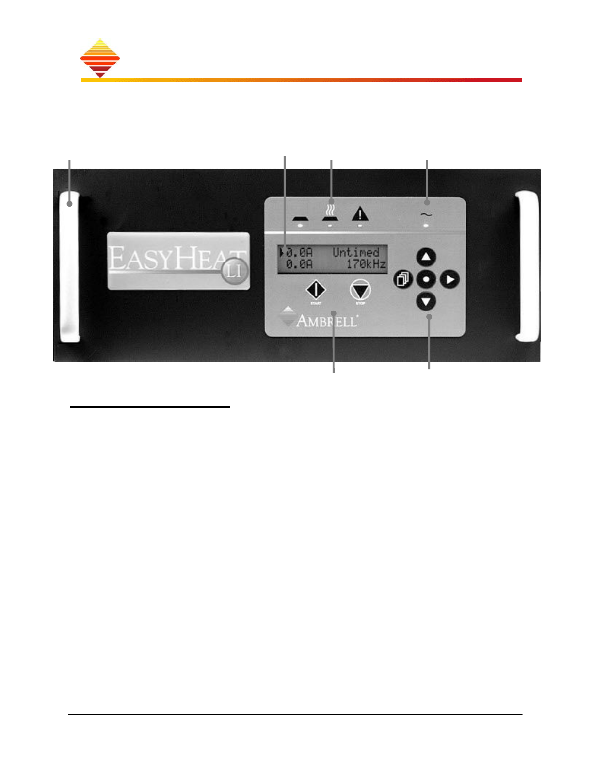
1.2Front and Rear Panels .......................................................................................................8
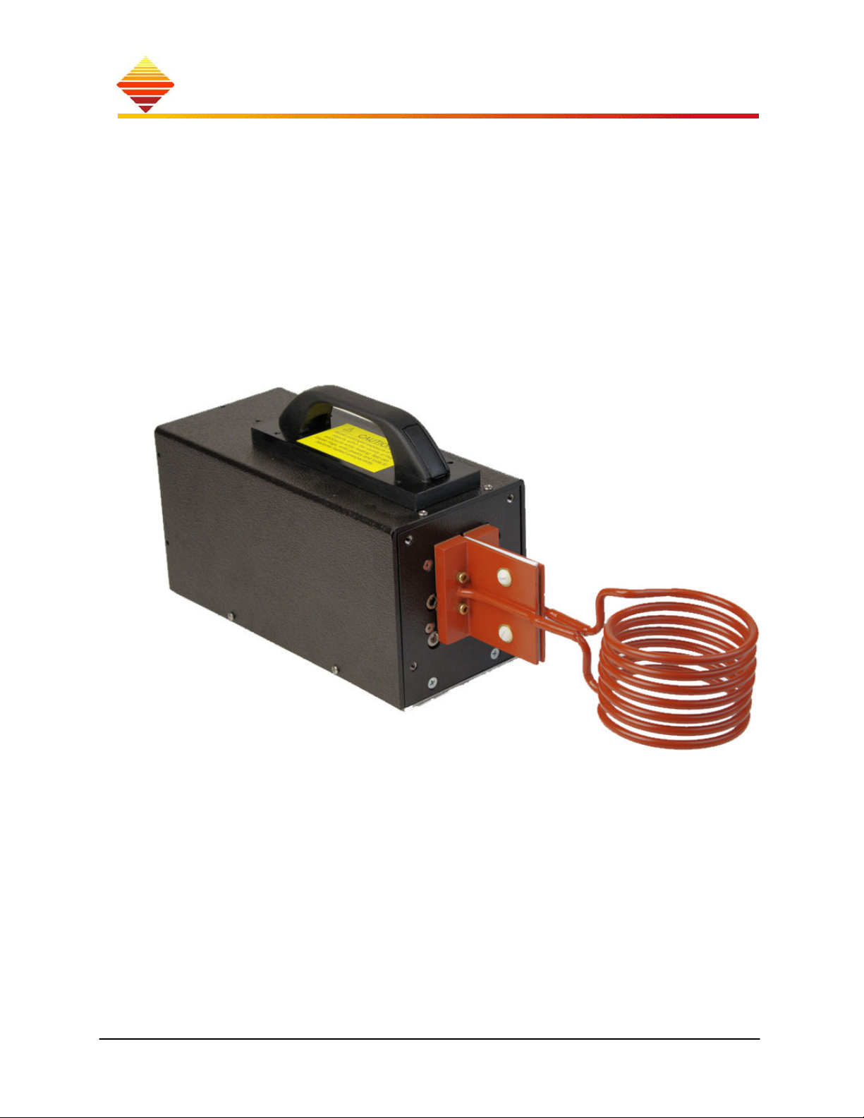
1.3Work Head ......................................................................................................................10
1.4Assembly.........................................................................................................................11
1.5Installation.......................................................................................................................14
2How Your EASYHEAT Works ........................................................................................17
2.1Home Zone......................................................................................................................18
2.2Control Zone ...................................................................................................................24
2.3Detailed EASYHEAT Operation ....................................................................................29
2.4Equipment Maintenance..................................................................................................32
2.5Before You Call Service… .............................................................................................34
2.6Calibration.......................................................................................................................36
2.7Smartburst Technology ...................................................................................................36
3Customizing Your EASYHEAT .......................................................................................39
3.1Rear Panel Connections ..................................................................................................39
3.2Serial Port (RJ45 modular)..............................................................................................45
3.3Optional Equipment ........................................................................................................53
3.4eVIEW Induction Heating Software ...............................................................................55
3.5Tap Adjustment ...............................................................................................................57
3.6Re-selecting Mains Voltage Range .................................................................................59
4Storing the System..............................................................................................................61
4.1System Disposal ..............................................................................................................61
4.2Sorting .............................................................................................................................61
5Regulation, Efficiency and Power Measurement ............................................................61
5.1RF Regulation and Efficiency .........................................................................................61
5.1.1Primary regulation techniques not used in EASYHEAT products:.........................62
5.1.2Power Measurement.................................................................................................64
6Technical Information .......................................................................................................66
6.1Mechanical ......................................................................................................................66
6.2Electrical..........................................................................................................................67
6.3Auxiliary Output Modes and Scaling Examples.............................................................69
6.4Environmental .................................................................................................................71
6.5Contact Information ........................................................................................................72
7Theory of Coil Design ........................................................................................................75

4
Precision Induction Heating
A
MBRELL®
801
-
9526
-
00.doc
Notes:
In this manual, these symbols indicate:
a step in a procedure
§manual sections
lighted indicators on the equipment
A notice that requires your special attention; may
pertain to safe operation of the equipment
A notice that requires your special attention due to
potential hazards to personnel or property

Introduction 5
A
MBRELL
801
-
9526
-
00.doc
Precision Induction Heating
1
1
I
In
nt
tr
ro
od
du
uc
ct
ti
io
on
n
Your EASYHEAT is a solid-state induction heating system that converts three-phase line
voltage to 4.2, 6, 9 or 10kW terminal power output (depending on model) over a range of
radio frequencies (RF) and voltages. This energy is delivered to a remote series-resonant
circuit - including your coil - where a precisely controlled magnetic field is created
around your work-piece. Available power to your process depends on the coupling
efficiency of your coil due to its geometry and proximity. Efficiency also depends on the
properties of your part; induction heating generally couples more efficiently to magnetic
steel and graphite parts than it does to non-magnetic stainless steel, aluminum and
copper.
Special features
Your EASYHEAT simplifies and improves your heating results with:
Touch-pad interface for control and programming
Backlit LCD simultaneous display of up to four data fields
Analog output – user programmable to represent Coil current, RF power or
operating frequency
electrically isolated remote work head
The power from your supply can be controlled:
manually from the front panel
remotely by your signals provided to the rear panel
remotely through a configurable serial port
from one of four 5-step profiles you specify
This selection is made from the touch-pad and can be changed at any time.
Unpacking
Your Ambrell EASYHEAT induction heating system has been carefully packed to arrive at
your facility in good condition. We suggest you inspect the shipping carton in the
presence of the carrier when the unit arrives at your facility. Look for dents, crushed
corners or torn cartons.
YOU MUST REPORT ALL DAMAGE DIRECTLY TO THE CARRIER.
Check to see that all the parts we shipped arrived at your plant with your manual:
EASYHEAT power supply
remote work head with cable
reference coil, attached to mounting blocks
this manual

Introduction
6
Precision Induction Heating
A
MBRELL®
Doc#
801
-
9526
-
00.doc
If you note damage, do not discard any of the exterior packing cartons; retain the
carton(s) so that the carrier's claim agent may inspect it. We will assist you in filing a
claim against the carrier should it be necessary to do so.
1
1.
.1
1
S
Sa
af
fe
et
ty
y
C
Co
on
ns
si
id
de
er
ra
at
ti
io
on
ns
s
Your EASYHEAT uses RF energy to raise the temperature of your work-piece. Most of
this RF energy is transmitted into the work-piece and some is transmitted into the air.
Physical Risks
During the HeatOn cycle, high RF voltages are present at your work-coil. There are
several risks, which we instruct you to protect against:
Electrical installations must be made by a qualified electrician and must conform to
applicable safety codes.
The equipment requires a connection to earth ground and does not make use of
neutral. Failure to connect earth (safety) ground will result in a potentially hazardous
condition. Do not omit this step!
High Temperatures: take steps to prevent personal contact with the work-piece you are
heating. Severe burns can result from contact at these temperatures! The mounting frame
on the bottom can heat during normal use, mount work-head to non-flammable surface,
and do not touch until cooled.
RF Voltages: we recommend that you provide protection against personal contact with
the work-coil when it is energized (Heat On).
Induction burns: the energized work-coil causes nearby metals to become heated; DO
NOT APPROACH ENERGIZED WORK-COIL WHILE WEARING OR CARRYING
METAL OBJECTS!
Electric and magnetic fields (EMF): EMF can affect Implanted Medical Devices.
Implanted Medical Device wearers should consult their doctor and the device
manufacturer before going near induction heating operations.

Introduction 7
A
MBRELL
801
-
9526
-
00.doc
Precision Induction Heating
Safety Circuits
Your optional normally-closed E-stop switch can be connected to the rear terminal block;
when the switch opens, output power is hardware-stopped. When the switch is re-closed,
the power supply returns to Ready (non-hazardous state). Your E-stop switch must be
isolated (dry-contact), capable of switching 0.1A @24Vdc.
The power supply is fitted with an external rear panel jumper which must be removed to
insert any safety switches required.
Class A equipment is intended for use in industrial environments. There may be
difficulties in ensuring electromagnetic compatibility in other environments due to
conducted and/or radiated disturbances.
Group 2 equipment intentionally generates radio frequency fields for the treatment
of materials

Introduction
8
Precision Induction Heating
A
MBRELL®
Doc#
801
-
9526
-
00.doc
1
1.
.2
2
F
Fr
ro
on
nt
t
a
an
nd
d
R
Re
ea
ar
r
P
Pa
an
ne
el
ls
s
Touch-pad & Display
All user-interface is conducted here
Status LEDs indicate what your EASYHEAT is doing
AC indicator is lighted when unit is turned on
LCD display provides operating information, navigation/programming prompts
START/STOP buttons enable front panel control of heating
navigation buttons are used to program and control the unit
Handles StatusDisplay AC indicator
START/STOP Navigation

Introduction 9
A
MBRELL
801
-
9526
-
00.doc
Precision Induction Heating
RF Output, Water
The remote work head attaches here. A specially-designed cable conveys RF energy to
the work head while plastic tubing routes cooling water to the coil (CLEAR), to the
capacitors (BLUE) and from (RED) the entire work head.
Your EASYHEAT uses circulating water to cool internal components and the coil; inlet
and outlet connections for the entire system are made at the rear. Internal flow switches
and temperature sensors are used to interrupt heating operations if this flow is inadequate
and are used to reduce heating if the internal temperature rises too high. Cooling water is
directed to and from the work head through the chassis and monitored by the power
supply.
Circuit breaker
This gang-switch controls the mains connection to the power supply. Trip level may vary
by model; see §4.
AC Line Inlet
This strain-relief fitting secures the provided 4-wire AC mains cabling.
Terminals (TB1)
Electrical connections are made here for all input and output signals (§3).
Grounding Studs
Safety Stud: Ensure that this auxiliary protective earth is connected to your facility
safety grounding before applying AC power.
Signal Stud: For signal grounding connections; not for equipment safety ground
connection!
TerminalsRF Output, terminals (cover removed)
Work Head WaterSystem Water
Circuit Breaker AC Line Inlet
Signal Stud Safety Stud

Introduction
10
Precision Induction Heating
A
MBRELL®
Doc#
801
-
9526
-
00.doc
1
1.
.3
3
W
Wo
or
rk
k
H
He
ea
ad
d
The energy generated by the power supply is converted at the work head to a form you
can use. The work head is comprised of an enclosure, a transformer, capacitor(s), coil
(sample coil shown) and required wiring. See §3 for instructions to change your
transformer tap settings.
Water is directed through the work head to draw-out excess heat developed naturally in
the internal components.
In cases where your coil presents a very restrictive path for the cooling water, we may
recommend the use of a ‘bypass-block’, §3. This may also require the use of an external
flow switch. (Ask your sales representative) Wiring must then be brought back to the
power supply from this switch.

Introduction 11
A
MBRELL
801
-
9526
-
00.doc
Precision Induction Heating
1
2
3
6
4 5
8
7
Y
X
1
1.
.4
4
A
As
ss
se
em
mb
bl
ly
y
Take these factors into consideration as you determine where to install your system:
availability of water and drain
availability of 3AC power
Attach work head & water
remove RF cover (dotted)
insert ring-terminated cable pair from
workhead; secure two ring-terminated
connection at posts as labeled
tighten strain relief nut
insert RED tube from work head
insert BLU tube from work head
insert CLEAR tube from work head
insert tubing for water outlet fully into
bottom port
insert tubing for water inlet fully into
top port
replace RF cover
…to remove tubing
push in on retaining rings, pull out tubes
Work head mounting base options
Your work head has been fitted with a two-part
mounting insert, which elevates and insulates the bottom
of the unit from your metal tabletop or mounting fixture,
reducing the amount of secondary heating you might
experience under certain sustained operating conditions.
Secured with four M6 nylon screws, this base can be
utilized or omitted in your mounting scheme. To mount:
remove nylon screws. Replace with four M6 stainless
steel screws long enough to pass through your
mounting surface and into the work head mounting base.
To prevent mounting screws from accidental contact with electrical componentry, use
screws which only thread into the mounting base up to 12.7 mm (0.5 in.).
Longer screws will damage equipment and pose an electrical hazard.

Introduction
12
Precision Induction Heating
A
MBRELL®
Doc#
801
-
9526
-
00.doc
Work-coil or reference coil (included with the unit)
A reference coil is included with your work head to ensure basic operation; while it is
suitable for use in heating, another coil may have been ordered for your use.
If you are attaching your own coil:
use 4mm Allen key to remove
the 4 screws securing the
reference coil
remove reference coil and
retain 2 O-rings from coil
mounting plate
re-use or use new O-rings [PN
117-0021]; insert in recessed
face of work head
secure coil with 4 screws
provided; tighten
Rack/panel Mounting
Your EASYHEAT is mountable in your panel or 19” rack (4U); observe these steps and
requirements:
unscrew/remove 4 rubber feet on unit base
(panel) provide cutout and mounting pattern per above; plan for M5 or M6 screws
ensure that rear of unit is supported when mounted
provide at least 736mm (29”) depth to permit water and AC power cable bend
secure unit with M5 or M6 hardware
2.375 (60.3)
18.3 (465)
2.25 (57)
17.5 (445)
7.1 (180)
Not to scale; inch (mm)panel cutout
0.5 (12)
1.437 (36.5)
4.00 (102) 6.89 (175)
0.40 (10)

Introduction 13
A
MBRELL
801
-
9526
-
00.doc
Precision Induction Heating
Cooling water
In the process of heating your work-piece, the current flowing in the work head and
power supply heats components, too. EASYHEAT provides a means of directing fresh
water into and through the components, enabling the water to pick-up the excess heat and
transfer it, either to a drain or to a heat exchanger which will then be recycled back to the
equipment.
Follow these important restrictions:
If used, fill re-circulating system with distilled or clean tap water
Do not use de-ionizing water systems
Do not use inhibited glycols in concentrations over 10% by volume as anti-
rust or anti-freeze agents; these agents reduce efficiency of cooling.
(If cooler is not supplied by us) Install a pressure regulator and a particulate
matter filter (both non-ferrous) in the supply of your cooling water.
Do not use ferrous pipe; it can lead to serious equipment damage!
Establish a cooling water source capable of adequate differential pressure and flow
(see §4.4)…
Provide inlet and outlet water per instructions §1.4
Flow monitoring
The amount of water flowing through your equipment is monitored, since operation with
inadequate or absent cooling water can result in damage to the coil or capacitor. When
flow is adequate to the heat sink and to the coil – see §4 – two internal switches are
closed. When flow falls off to the heat sink or the coil, one or both of the switches open
and the power supply senses it, halts RF power and indicates Fault.
No action required by you; internal connections.

Introduction
14
Precision Induction Heating
A
MBRELL®
Doc#
801
-
9526
-
00.doc
1
1.
.5
5
I
In
ns
st
ta
al
ll
la
at
ti
io
on
n
Mains service
Plan a 4-wire routing for three phases and earth ground
Determine appropriate disconnect fusing and wire gauge
Place the disconnect near the power supply and in sight of the operator
Mains connection
ensure fused disconnect is opened
connect the provided AC mains cable to your 3-phase source and [GREEN] safety
ground.
Re-selecting Mains Voltage
The equipment labelling indicates the mains voltage range for which your system has
been configured. If you have a need to move the system into a facility with a different
mains voltage range, follow the instructions in §3.6
We recommend that you install a fused disconnect switch (not supplied by Ambrell)
in the branch circuit supplying the equipment. Base your selection of fuses on the
equipment nameplate data.
Your system has been sealed (circle); if the seal is
damaged, internal mains voltage range settings may
have been changed; verify this setting before connecting
to AC mains power. This label (arrow) indicates sealed
mains voltage range. We provide one set of replacement
seal and voltage range label.
The equipment requires a connection to earth ground and does not make use of neutral.
Failure to connect earth (safety) ground will result in a potentially hazardous condition. Do not
omit this step!
Electrical installations must be made by qualified personnel and must conform to applicable
safety codes.
Do not connect 230V models to 440V mains; damage and hazard will result!

Introduction 15
A
MBRELL
801
-
9526
-
00.doc
Precision Induction Heating
Start-up display
You are ready to apply power to the EASYHEAT
turn on water to your system
turn on fused disconnect supplying your system
turn on circuit breaker at rear of EASYHEAT
ensure appropriate line voltage selection in Control settings (§2.2)
Upon power-up, certain important information about your EASYHEAT is displayed:
Output power capability: Depending on the unit
you purchased.
Language Suite; your system display is equipped
with a selectable 5-language suite:
EN/ES//FR/DE/IT; this capability is reflected in
this screen
Firmware versions: There may be instances where
we need this information from you. n.nn
represents the version numbers of the Display or
Main firmware
SYS ID #: Is used to connect to remote monitoring
software. Refer to § 3.4 for more information on
eVIEW Induction Heating Software
You can also view the output power capability screen, Language Suite screen and
firmware versions screen when the unit is ON; while in the Control Zone, §2.2, press
▲to repeat the Start-up display screens
The next section explains what you see when the unit is operating in the Home zone.
EASYHeat 5060
6kW RF Power
Display: Vn.nn
Main: Vn.nn
440-520 VAC
EN/ES/FR/DE/IT
SYS ID #: nnnnn


How Your EASYHEAT Works 17
A
MBRELL
801
-
9526
-
00.doc
Precision Induction Heating
2
2
H
Ho
ow
w
Y
Yo
ou
ur
r
E
EA
AS
SY
YH
HE
EA
AT
T
W
Wo
or
rk
ks
s
When you turn HeatOn, (details, next page) this equipment concentrates an
electromagnetic field within the coil diameter. When you put your metal part into the
coil, this field causes internal electric currents to circulate in your part. Friction from
these currents heats your part.
With HeatOn, both Setpoint (your selected output level) and Output Level (actual
power or current delivered to your part) are displayed. Typically, the Output Power (kW)
is highest when your part is in the coil and it returns to a lower level when you remove
your part; output current (A) is normally held as set. (For detailed explanations or to
understand operation that is not typical, see §2.3)
This equipment is designed to operate simply. This section presents EASYHEAT operation
in two parts:
Home zone: your EASYHEAT operates in this zone when you first apply
power. The factory settings enable you to get right to work heating parts by
operating the front panel. From the Home zone, you can adjust output levels,
set the timer and turn RF power on and off. Simple heating jobs may never
require you to use features outside this zone.
Control zone: press this button to make use of the full set of EASYHEAT
capabilities by changing any of the operating characteristics. Refer to §2.2 to
customize your EASYHEAT.
Return: pressing this button always returns display to the Home zone
Next is a simple example of operation from the Home zone. In it you will operate your
EASYHEAT by:
starting from the front panel
using 2-button START (requires STOP to turn off heat)
(Other operating characteristics are discussed in the Control zone section.)
After this example, the front panel display, LED and touch-pad features are explained.
The Control zone is explained in detail in the next section.
LED Status and system notices are relevant if your part is in the coil during
HeatOn. Status and notices displayed after you remove your part can be ignored

How Your EASYHEAT Works
18
Precision Induction Heating
A
MBRELL®
Doc#
801
-
9526
-
00.doc
2
2.
.1
1
H
Ho
om
me
e
Z
Zo
on
ne
e
When you turn it on, EASYHEAT operates in the Home zone (illustration). Within this
zone, you can adjust output levels, set the timer and turn RF power on and off:
Simplest example…
In this example, you heat the part at 100A output.
►0.0A Untimed
0.0A 0kHz
►100.1A Untimed
0.0A 0kHz
►100.1A Untimed
100.1A 100kHz
1 3○
Ready HeatOn Fault
○○
Ready HeatOn Fault
2
○○
Ready HeatOn Fault
2
Timer
cycle or continuous
Setpoint
required output level
Output level
(A, W, % or units)
Output frequency
Status LEDs
indicate what your EASYHEAT is doing:
READY: waiting to heat; no faults detected
HEAT ON: power is being output
FAULT: heating interrupted, fault detected
AC Power
indicates your
EASYHEAT is
turned on
Navigation
to program and
confi
g
ure
Home Zone Display
START/STOP
to initiate heating from front panel

How Your EASYHEAT Works 19
A
MBRELL
801
-
9526
-
00.doc
Precision Induction Heating
Do this... Observe...
open water-valve for the system check drain; ensure water is flowing
check the work-coil ensure there is no work-piece yet
check condition of (any) safety
barriers or limit switches
all safety devices are clear, electrically
closed
turn on EASYHEAT AC Power and Ready LEDs (are ON)
note display: ensure Setpoint is selected (example)
press ▲, adjust until: 100A
Within the Home zone, use these buttons to adjust Setpoint and Timer
(indicated with the display pointer ►); press once to make a single-step
adjustment, or you can hold the button to scroll quickly to a new value.
press ▲, adjust until: 10.00s
secure unheated part in coil part not contacting coil; do not hold
press START HeatOn, Ready
Ready only, when timer expires (HeatOff
remove heated part from coil avoid contact with heated portions
secure unheated part in coil part not contacting coil; do not hold
press START HeatOn, Ready
press STOP Ready only
Press START to begin induction heating (Home zone only)
Press STOP to halt induction heating (2-button start type, below). STOP
signal from front or rear panel always halts induction heating.
remove heated part from coil avoid contact with heated portions
Timed heating…
In this example, you heat the part at 100A output for 10 seconds.
Do this... Observe...
press ►, select Timer Untimed
Button is used to move the display pointer from one data field to the next.

How Your EASYHEAT Works
20
Precision Induction Heating
A
MBRELL®
Doc#
801
-
9526
-
00.doc
Display features
.
At the top left corner of the screen, this is
your desired output level, displayed in RF
amps. Larger values result in faster heating
or hotter parts.
With the pointer (►) on Setpoint, you can increase or decrease the setting with the
▲/▼buttons.
EASYHEAT works to match the RF output to this setting when the RF power is on
(HeatOn). In the Home Zone, ►moves the cursor between Setpoint and Timer
At top right, use the timer to control the
duration of your heating.
With the pointer (►) on Timer, you can increase or decrease this setting to values
between 30 milliseconds and 9999 seconds with the ▲/▼buttons.
The timer begins counting down when you START. To display elapsed cycle time, move
the pointer to Untimed, then press STOP; elapsed cycle time is then displayed during
HeatOn. (Ensure: 2button Start §2.2 when using timer!)
At the bottom left corner of the screen, this is
the actual RF output (always 0.0 when the
heat is turned off).
When the output power is turned on, this displays the output in terms of RF coil power or
current. The output level can be shown in RF Amps or RF Watts (press to toggle).
At the bottom right corner of the screen, the
frequency at which the supply is heating is
shown.
This is the resonant operating frequency and is the result of your coil in combination with
the work head’s internal capacitance. (Note: You cannot ‘set’ this frequency other than
through your selection of heating coil and capacitor.)
When Ready after first turning on the EASYHEAT, the frequency is displayed as 0
kHz. During the first heat cycle (HeatOn), the frequency value shows you what the
resonant (most efficient heating) point is. When the heat is turned off, the display will
show you where it will begin to resonate on the next heat cycle - based on the recent
heating cycle. Sometimes, you may see that the output frequency approaches either end
of the operation range of EASYHEAT and the display advises you to increase or decrease
capacitance. Please call your Ambrell office for assistance should this happen and we will
supply you with the appropriate capacitors.
Setpoint Timer
Out
p
ut Fre
q
Setpoint Timer
Out
p
ut Fre
q
Setpoint Timer
Out
p
ut Fre
q
Setpoint Timer
Out
p
ut Fre
q
This manual suits for next models
4
Table of contents
Other Ambrell Heating System manuals
Popular Heating System manuals by other brands

Carrier
Carrier WEATHERMAKER 48A2 Series Wiring diagrams

STIEBEL ELTRON
STIEBEL ELTRON LWZ 180 Administrator's Manual for Operation and Installation

Viessmann
Viessmann Vitoligno 300-H Operating Instructions for the System User

aldes
aldes EVEREST XV installation instructions

VTS Medical Systems
VTS Medical Systems VOLCANO Series manual

Conel
Conel CLEAR FILL operating instructions